1
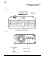
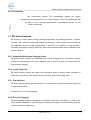
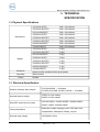
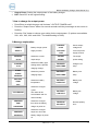
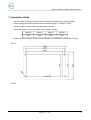
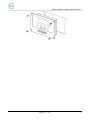
BP Smart Battery Charger User Manual V1.1 BP Series SMART BATTERY CHARGER USER MANUAL Version 1.1 Date: May, 2014 TBB Power Co. Ltd. 1 BP Smart Battery Charger User Manual V1.1 Contents 1.General Safety Information.........................................................................................................................................1 2.INTRODUCTION.......................................................................................................................................................2 2.1 Description........................................................................................................................................................2 2.2 BP Series Features............................................................................................................................................2 2.3Indicator Lights and Settings on the Front Panel..............................................................................................5 3.INSTALLING GUIDE.................................................................................................................................................7 3.1 Material List......................................................................................................................................................7 3.2 Preparing for Installation..................................................................................................................................7 3.3 Installing BP Series...........................................................................................................................................8 3.4 Installing Battery Temperature Sensor.............................................................................................................9 4.OPERATION..............................................................................................................................................................11 4.1 Dip Switch Setting..........................................................................................................................................11 4.2Charging Batteries...........................................................................................................................................12 4.3 Simultaneously Recharging and Power Supply.............................................................................................13 4.4 Using A Generator as Source Power...............................................................................................................13 5.TECHNICAL SPECIFICATION...............................................................................................................................14 5.1Physical Specifications....................................................................................................................................14 5.2 Electrical Specification...................................................................................................................................15 5.3 Protection Features.........................................................................................................................................15 5.4 Approvals........................................................................................................................................................15 6.MAINTENANCE AND TROUBLESHOOTING.....................................................................................................17 6.1 Maintenance....................................................................................................................................................17 6.2 Troubleshooting..............................................................................................................................................17 7.REMOTE CONTROLLER........................................................................................................................................19 7.1 Brief Introduction...........................................................................................................................................19 7.2 LCD Message Explanation.............................................................................................................................19 7.3Installation Guide.............................................................................................................................................20 8.REMOTE DISPLAY..................................................................................................................................................22 8.1 Brief Introduction...........................................................................................................................................22 8.2 Installation Guide............................................................................................................................................22 TBB Power Co. Ltd. 2 BP Smart Battery Charger User Manual V1.1 About This Manual Purpose and Scope This manual describes TBB battery charger’s features, explains how it charge batteries, and provides procedures for its installation and gives some tips for the troubleshooting. But it does not mention the details of the particular brands of batteries. Please consult the battery manufacturer for this information. Audience The manual is for anyone intending to install and operate a TBB BP Series battery charger. Warning This charger is not designed for any life retaining equipment. TBB Power Co. Ltd. 3 BP Smart Battery Charger User Manual V1.1 About TBB TBB Power is a dedicated designer and manufacturer of sophisticated and environmentally rugged power electronic equipment. We are offering a wide range of power conversion product from battery charger, standalone inverter, inverter charger combination and solar charge controller. We ensure consistent product quality by subjecting every product to strictly choice of superior quality components, rigorous testing and burn-in through out the production process. TBB Power is certified by TUV in accordance with ISO9001 and can be your reliable power solution provider. Disclaimer Unless specially agreed in writing, TBB Power Co.,Ltd Take no warranty as to the accuracy, sufficiency of suitability of any technical or other information provided in this manual or other documentation. Assumes no responsibility or liability for loss or damage, whether direct, indirect, consequential or incidental, which might arise out of the use of such information Contact Information TBB Power Co.,Ltd TBB Power GmbH Web: www.tbbpower.com Web: www.tbbpower.com Tel: +86-592-5212299 Tel: Fax: +86-592-5796070 Mobile: +49 (0)176 5688 0608 Email: [email protected] Email: [email protected] +49 (0)211 930 77331 TBB Power Co. Ltd. 4 BP Smart Battery Charger User Manual V1.1 1. General Safety Information 1) Before using the charger, read all instructions and cautionary markings on the charger, the batteries, and all appropriate sections of this manual. 2) Use BP Series battery charger only for its use as intended. 3) Use BP Series battery charger only in well ventilated rooms. Do not expose the charger to rain, snow, spray, or bilge water. To reduce risk of fire hazard, do not cover or obstruct the ventilation openings. Do not install the charger in a zero- clearance compartment. 4) Always interrupt the power supply when doing repair work on the unit. 5) Recommend that all wiring be done by a certified technician or electrician to ensure adherence to the local and national electrical codes applicable in your application. 6) Always checking that existing wiring is in good condition and that wire is not undersized. Do not operate the charger with damaged or substandard wiring. 7) Always use socket which are earthed and secured by earth leakage circuit breaker. 8) Batteries contain aggressive acids. Avoid the contact with the battery fluid agent. If a contact with battery fluid agent should occur, then rinse the affected parts of the body or clothing etc. with plenty cold water. It is imperative to seek medical treatment from a doctor with injuries caused by acid. 9) DO NOT disassemble the charger by yourself, which may result in a risk of electrical shock or fire. Always refer to professional electrician or our local distributor for support. 10) ALWAYS interrupt both the AC and DC connect when doing repair work. 11) DO NOT expose lead acid batteries to a lit cigarette, sparks or flames because they produce flammable gasses and could explode. 12) BP Series charger was designed to charge rechargeable lead acid battery, Freedom, Flooded, GEL, AGM. NEVER charge other type battery or NON-rechargable battery. 13) Never try to charge a frozen battery. There is danger of explosion. In this case, place the battery at a frost resistant location and wait until the battery has adapted to the ambient temperature. Only by then, start the charging process. 14) This appliance is not intended for use by persons (including children) with reduced physical, sensory or mental capabilities, or lack of experience and knowledge, unless they have been given supervision or instruction concerning use of the appliance by a person responsible for their safety. 15) Children should be supervised to ensure that they do not play with the appliance. 16) If the supply cord is damaged, it must be replaced by the manufacturer, its service agent or similarly qualified persons in order to avoid a hazard. TBB Power Co. Ltd. 1 BP Smart Battery Charger User Manual V1.1 2. INTRODUCTION 2.1 Description 2.1.1 Front Panel 2.1.2 Rear Panel TBB Power Co. Ltd. 2 BP Smart Battery Charger User Manual V1.1 2.1.3 Accessories The Temperature Sensor (TS) automatically adjusts the charge according to the temperature of one of the batteries. With a TS installed, the unit provides a more accurate temperature- compensated charge for the battery connected. 2.2 BP Series Features BP Series is a smart battery charger designed specifically for following batteries: Freedom, Flooded, GEL, AGM. By using high frequency technology, it has compact structure and can be installed or stored in small compartments. It has AC to DC isolation, a surge protector, automatic multi stage charging, and many other safety features which reduce potential shock and fire hazards. 2.2.1 Automatic Multi-stage Charging Curve BP Series battery charger has automatic max 6 steps charging curve and delivers nominal current for approximately 75% of the charging cycle. It ensures to give your battery and full, fast and safe charging. 2.2.2 Inside Timer Set BP Series battery charger will switch from absorption stage to floating stage according to either the current drop to the nominal level or the timer exceed the setting value. 2.2.3 Dip Switches BP Series battery charger has dip switches for you to choose: charge mode, battery type and to support R/C or R/D. Please refer to 4.1 for detail setting. 2.2.4 Recycle Charging BP Series battery charger is designed to permanently connect to the battery. In order to get rid of possible sulphation in case of long term floating, the charger will automatically goes into recycle charging in 14days time. TBB Power Co. Ltd. 3 BP Smart Battery Charger User Manual V1.1 2.2.5 Simultaneous Multi-battery Bank Charging BP Series battery charger has multi separate Dc positive terminals (12A has two banks, 20A, 25A and 40A has three banks) which allow charging multi batteries simultaneously. The total current into the batteries is a maximum of either 12A, 20A, 25A or 40A, depending on the model, which is divided amongst the batteries according to their state of discharge. WARNING The multi outputs are not independently voltage regulated so it is important to avoid systems with mixed types of batteries. 2.2.6 Isolated Design The output banks are isolated by the electronically design in the circuit. It prevents the current flow between the banks and the flow backwards from battery to battery charger. 2.2.7 Special Silent Design User-friendly special silent design. The fan of charger will stop working after the charging current drop to small amount for a period of them. And it will also automatic turn to work condition if inner temperature increased. 2.2.8 Parallel design for recharging and power supply. BP Series smart battery charger can be used to supply your DC load and charge your battery simultaneously. Specially designed software is being programmed to avoid overcharging your battery at this circumstance. WARNING If your DC load is voltage sensitive and did not permit high input over 14.5VDC, do not connect DC load while charging if you are charging your FREEDOM batteries. If the ambient temperature is below 80F (26.7℃), the voltage will increase as result of TBB Power Co. Ltd. 4 BP Smart Battery Charger User Manual V1.1 the temperature compensation. The compensate rate is 3.3mv/cell, please add it above the voltage you selected, then you'll have the correct output voltage of charger. 2.2.9 Power Supply Choice Easy to choose, the BP Series can work as a power supply by dip switch. It is meant that the output of the battery charger is a fixed voltage. It is not meant for charging batteries. The battery type and battery temperature are ignored in this mode. The remote battery temperature sensor does not compensate the voltage, but the battery over-temperature shutdown is still active. Through this mode, the charger can output neat DC at 13.5V (12V models) and 27V (24v models) 2.2.10 Built-in Safety BP Series battery charger provides the following protection features: 1) Unit shutdown if there is a short circuit on output; 2) Electronic protection for reversed polarity; 3) Unit shutdown in event of battery over voltage; 4) Unit reduces output in event of battery charger over temp, and maintain the temp at a balance level; 5) Unit shutdown in event of battery over temp, and automatic operation reset once the temp comes down. 2.2.11 Automatic Temperature Compensation The remote battery temperature sensor is a standard accessory with BP Series battery charger. With it is plugged to the battery charger, the unit provides a more accurate temperature-compensated charge for the battery to which the sensor is attached automatically. 2.2.12 High Ambient Temperature Rated BP Series charger was designed to work at full load up to 40 ℃. 2.2.13 Protective Lacquer on Each PCB To protect the PCB from the moisture and corrosion, each BP Series battery charger has TBB Power Co. Ltd. 5 BP Smart Battery Charger User Manual V1.1 been sprayed by protective lacquer on PCB. 2.2.14 Optional remote controller or remote display available. Easy to switch the signal between remote controller and remote displayer by dip switch. Please read the chapter 7 for the details setting and content. TBB Power Co. Ltd. 6 BP Smart Battery Charger User Manual V1.1 2.3 Indicator Lights and Settings on the Front Panel LED Sign Reason Battery charger disconnected Power supply failure Incorrect power supply connection OFF Mains voltage too low "Power" Mains fuse blown Battery connection not good FLASHING Wrong voltage battery connected (24V to 12V battery charger) ON Batteries charging(constant current stage) "Charging" FLASHING "Charged" "Reverse Polarity" "Charging" and "Charged" Batteries charging(constant voltage stage) ON Batteries charged (Floating) ON Polarity inversion on output FLASHING FLASHING Charger over tem, charger will reduce the output power Will reduce the output power, then shut off. TBB Power Co. Ltd. 7 BP Smart Battery Charger User Manual V1.1 3. INSTALLING GUIDE 3.1 Material List The Unit is packed with the following materials: 1) User's Manual 2) Temperature Sensor Please confirm the series number on the color box and the back of the product is the same. 3.2 Preparing for Installation 3.2.1 Location Please install BP Series battery charger in a location that meets the requirements as following: Dry: The unit is intended for use in a dry location. Do not allow water or other fluids to drip or splash on it. Do not mount the charger in an area subject to rain, spray or splashing bilge water. Clean: Do not expose the unit to metal filings or any other form of conductive contamination. The presence of conductive contamination can cause damage and void your warranty. Cool: For best performance, the ambient air temperature should be between 32F (0 ℃) and 95F (30 ℃), the cooler the better. At higher ambient temperature, BP Series battery charger can work, but the output current will be automatically reduced to protect the charger from high internal temperatures. Ventilated: Allow at least 4 inches (10cm) of clearance around all sides of the battery charger for air flow. Ensure the ventilation openings on the unit are not obstructed. If mounting in a compartment, ventilate the compartment with louvers or cut-outs to prevent overheating. Safe: Not to install in areas containing gasoline tanks or fittings. Close to AC junction box: Avoid the use of extended wire lengths if possible. TBB Power Co. Ltd. 8 BP Smart Battery Charger User Manual V1.1 Close to batteries: Avoid excessive cable lengths and use the recommended wire lengths and sizes. Undersized or overly long cables may affect charging accuracy. 3.2.2 DC Wiring The DC wiring must meet the following requirements: Recommend sections for battery cables: 12A — 4mm2 minimum (AWG 11) 20A/25A — 8mm2 minimum (AWG 8) 40A — 13mm2 minimum (AWG 6) 3.3 Installing BP Series WARNING Shock and Energy Hazards Be sure to read the safety guidelines and pay attention to all cautions and warnings throughout the installation procedure. The installer is responsible for ensuring compliance with the installation codes for your particular application. Disconnect all source of AC and DC power before proceeding. CAUTION Reverse Polarity Before making the final DC connection, check the cable polarity at both the battery and the charger. Positive must be connected to positive; negative must be connected to negative. TBB Power Co. Ltd. 9 BP Smart Battery Charger User Manual V1.1 Figure 3.1 installation guide for connecting BC and batteries Mounting: Mount the battery charger on a vertical surface, using the mounting holes provided. Mounting hardware should be corrosion resistant. Recommend to use all four mounting holes. Connecting DC Wiring for Batteries WARNING All the batteries you are charging must be the same type, that is, should be all flooded, or gel, or AGM. Plan the route the DC wires will follow trying to make it as short as possible. Install the DC circuit breaker or fuses in the battery positive circuits close to the battery. Fully insert each positive wire into the positive terminal on the charger. Tighten the connector and test that the wire is secure. Connect the positive cable from the positive wire terminals on the charger to the battery fuse or breaker, which should be installed on the battery positive terminals. Leave the DC disconnects or breakers in the OFF position until installation is complete. Leaving them off helps prevent sparking when you actually make the connection. Connect AC Wiring TBB Power Co. Ltd. 10 BP Smart Battery Charger User Manual V1.1 Make sure the AC source circuit is disconnected by turning off the breaker feeding the circuit, unplugging from shore power and disconnecting any other power sources such as a generator. Grounding Do not make an ungrounded connection. Improper connection can result in risk of an electric shock. Battery charger must be grounded to reduce the risk of electrical shock. The AC input ground wire must be properly connected to ground in accordance with all applicable electrical codes. Meeting electrical codes is achieved by connecting the ground conductor of the AC input cable to a properly grounded ground terminal in the AC distribution panel. 3.4 Installing Battery Temperature Sensor Strongly recommend to install the temperature sensor which is offered together with the battery charger for a pro- per charging of your batteries. TBB Power Co. Ltd. 11 BP Smart Battery Charger User Manual V1.1 4. OPERATION 4.1 Dip Switch Setting Switch 1: Default is OFF OFF: battery charger function ON: Power supply function. Output voltage: DC13.5V+/-0.6V(12V models), DC27V+/-0.6V(24V models). Switch 2-4: Output voltage setting: 12V MODELS Battery Switc Switc Switc Absorption Floating type Flooded Freedo h2 OFF h3 OFF h4 OFF volt 14.4V volt 13.4V OFF OFF ON 14.8V 13.8V OFF OFF ON ON OFF ON 14.3V 14.6V 13.8V 13.6V Battery Switc Switc Switc Absorption Floating type Flooded Freedo h2 OFF h3 OFF h4 OFF volt 28.8V volt 26.8V OFF OFF ON 29.6V 27.6V OFF OFF ON ON OFF ON 28.6V 29.2V 27.6V 27.2V m GEL AGM 24V MODELS m GEL AGM Please read your manual of battery or consult the battery manufacture to set the output voltage accordingly. Switch 5-8: Choose R/C or R/D: Type R/C R/D Switch 5 ON OFF Switch 6 ON OFF Switch 7 OFF ON Switch 8 OFF ON 4.2 Charging Batteries Before you start to charge batteries, please read the "General safety information" and take all safety precautions when working with batteries. Read the section 4.1 to set the dip switch at proper situation. TBB Power Co. Ltd. 12 BP Smart Battery Charger User Manual V1.1 Check the manual or manufacturer of your battery and set the dip switch 2-4 at the proper situation according to the recommended absorption and floating voltage. Plug in the temperature sensor to the battery charger and fasten the sensor head directly to the battery. To assure the right charging and avoid the chance of over¬-temp in battery, it is strongly recommended the temperature sensor should be connected during charging. When the charging is completed, the battery charger enters into Floating Mode, and the "charged" light is ON. Recharging: BP Series battery charger will begin a charging cycle 14 days after the last cycle. WARNING The battery charger is designed to have no output if no battery is connected. 4.3 Simultaneously Recharging and Power Supply It is strongly recommended to check your DC load requirement if you are connecting DC load while charging. WARNING If your DC load is voltage sensitive and did not permit high input over 14.5VDC (12V models) and 29VDC (24V models), do not connect DC load while charging if you are charging your FREEDOM batteries. 4.4 Using A Generator as Source Power Many generators provide output voltage that is modified sine wave (MSW) rather than the true sine wave (TSW) that your utility provides. TBB does not permit the use of BP Series + with modified sine wave generator due to increased heating of the charger. TBB Power Co. Ltd. 13 BP Smart Battery Charger User Manual V1.1 5. TECHNICAL SPECIFICATION 5.1 Physical Specifications Dimensions Weight Enclosure Assembly Fixture 12V12A-2 W PFC 300 x 190 x 80mm 12V12A-2 W/O PFC 300 x 190 x 80mm 24V12A-3W/OPFC 300 x 190 x 80mm 12V25A-3 W PFC 350 x 190 x 80mm 12V25A-3 W/O PFC 300 x 190 x 80mm 12V40A-3 W/O PFC 24V20A-3W/OPFC 350 x 190 x 80mm 350 x 190 x 80mm 12V40A-3WPFC 330 x 210 x 85mm 12V12A-2 W PFC 2.5kg 12V12A-2 W/O PFC 2.6kg 24V12A-3W/OPFC 2.6kg 12V25A-3 W PFC 3.0kg 12V25A-3 W/O PFC 2.7kg 12V40A-3 W/O PFC 3.3kg 24V20A-3W/OPFC 3.3kg 12V40A-3WPFC 3.2kg Aluminum with anodized, flame proof plastic Wall-mounted Screws 5.2 Electrical Specification Number of battery bank outputs Nominal battery voltage Rated DC output current (total) Charge Algorithms Nominal input voltage 12V12A,24V06A — 2 isolated 12 V25A,24 V12A& 12V40A, 24V20A — 3 isolated 12VDC for 12V models 24VDC for 24V models 12V12A 12ADC; 12V25A 25ADC; 12V40A 40ADC; 24VI2A 12ADC; 24V20A 20ADC Automatic 6 steps charging curves. Soft start, bulk, compensation, absorption, floating, recycle. 185-265VAC 50Hz, TBB Power Co. Ltd. 14 BP Smart Battery Charger User Manual V1.1 Charge algorithms Automatic max 6 steps Battery temperature compensation Automatic active when temperature sensor plug in Absorption and Float voltage 4 options, please check "4.1 dip switch setting" Power supply mode nominal output 12V : 13. 5+/-0. 6VDC voltage 24V : 27+/-0. 6VDC Efficiency 0.85 PFC >95% 5.3 Protection Features Reverse Polarity Electronic protect Battery charger over temperature Reduce output power while charger in overtemperature condition Battery temperature as sensed by the battery Battery over temperature temperature sensor (if installed) results in charger Will not start charging if any battery voltage is greateratthan 15.0VDC (12V models) and shutdown a battery temperature of 50℃ Battery over voltage limits 30VDC(24V models) Will not continue charging if any battery voltage is greater than 16.0VDC (12V models) and 32VDC(24V models) 5.4 Approvals LVD EN60335-1, EN60335-2-29 EMC EN55014-1/EN55014-2,EN61000-3-2/EN61000-3-3 TBB Power Co. Ltd. 15 BP Smart Battery Charger User Manual V1.1 6. MAINTENANCE AND TROUBLESHOOTIN G 6.1 Maintenance WARNING Risk of Electrical Shock BP Series battery charger contains no user serviceable components. Do not attempt servicing unless you are a qualified technician or electrician. Contact your dealer or the manufacturer for service information. Cleaning: BP Series battery charger contains solid-state electronic components that require no maintenance. The best care you can give the unit is to protect it from contact with liquids, spray, or fumes which may cause corrosion. Disconnect all AC and DC power and clean the outside of the case and wiring with a damp cloth if you suspect it has come in contact with battery fluid, salt water, gasoline or oil, or other corrosive material. Corrosion on the battery terminal posts may be removed with a solution of water and baking soda. Routing check: Periodically, check all wiring connections, DC and AC, to be sure they have not loosened or deteriorated. Also check all cable clamps to ensure they are tightly fastened. 6.2 Troubleshooting Display Condition TBB Power Co. Ltd. 16 BP Smart Battery Charger User Manual V1.1 "Power" indicator light is OFF "Power" indicator light is flashing Battery charger disconnected Power supply failure Incorrect power supply connection Mains voltage too low Mains fuse blown Battery connection not good Wrong voltage battery connected (24V to 12V battery charger) "Reverse polarity" indicator light ON Polarity reversion on output Charger over temp. charger will reduce the “Reverse polarity" indicator light flashing output power "Charging" & "Charged" indicator light flashing Will reduce the output power, then shut off. TBB Power Co. Ltd. 17 BP Smart Battery Charger User Manual V1.1 7. REMOTE CONTROLLER Remote controller and remote display are available for BP Series battery charger. You can buy them from the local distributor separately. 7.1 Brief Introduction For your convenience, remote controller of BP Series smart battery charger offers plenty of information and powerful function. It has user friendly setting and design: • 55x18mm LCD displayer • All parameter of charger is visible and settable through remote controller • Battery condition is visible • Output power can be limited to avoid main switch to be tripped in case of small shore power available only • Together with the remote controller, 3 meters cable was supplied. 7.2 LCD Message Explanation 1. a) LED indicator: Power: light on when the battery charger is power on and it is set to communicate to R/C by dip switch. b) 2. Fault: error alarm and LCD display the fault content. Buttons: a) Set: Set the parameter b) Enter: Page Switch and switch on/off the background light. TBB Power Co. Ltd. 18 BP Smart Battery Charger User Manual V1.1 c) Output Power: Setting the output power of the battery charger d) RST: Reset R/C to the original setting. * How to change the output power: 1) Press Enter to switch the page until it shows " OUTPUT POWER xxx%" 2) Press the "Output Power" button for several seconds until the percentage on the screen is freshing. 3) Press the "Set" button to choose your setting for the output power. (5 options are available: 20%, 40%, 60%, 80% and 100%. The default setting is 100%) 3.Message explanation: CURRENT POWER Battery charger power SUPPLY supply function. CURRENT 00.0A FLOODED 14.4V STAGE CONST CURRENT BATTERY TEMP 25°C 20.0A Shows output voltage and VOLTAGE current at power 14.4V supply function. Shows the current OUTPUT The output output amps POWER power setting CHARGED Charger over Shows the battery type Setting and the present charging voltage. Shows the present charging stage OVER TEMP BATTERY OVER TEMP Shows the battery temperature BATTERY OVER VOLT temp. Battery over temp Battery over voltage. Shows the charged cycles. CYCLES 0000 The value will be accumulated until it is BATTERY Battery low LOW VOLT voltage REVERSE Reverse polarity POLARITY error. reset manually CHARGED TIME 00000H00M Shows the charged time since the battery charger is power on Shows the charged CHARGED amps hour since the 000000 AH battery charger is power on TBB Power Co. Ltd. 19 BP Smart Battery Charger User Manual V1.1 7.3 Installation Guide 1. It is not a water proof type. Please locate a position of which water is not accessible. 2. Please cutting the hole as per size offered by following Pic A: 122mm X 76mm 3. Connect cable to remote controller and battery charger. 4. Put the dip switch on correct position on the battery charger: 5. Switch 5 Switch 6 Switch 7 Switch 8 ON ON OFF OFF Please use screw (M4) to fix the remote controller onto dashboard, please refer to pic B. PIC A: PIC B: TBB Power Co. Ltd. 20 BP Smart Battery Charger User Manual V1.1 TBB Power Co. Ltd. 21 BP Smart Battery Charger User Manual V1.1 8. REMOTE DISPLAY For your convenience, remote display of BP Series smart battery charger offers the same LED display as the ones on the battery charger. Together with the remote display, 3 meters cable was supplied. 8.1 Brief Introduction LED indicator: Please refer the manual 2.3 and 6.2 for the details. 8.2 Installation Guide 1. It is not a water proof type. Please locate a position of which water is not accessible. 2. Please cutting the hole as per size offered by following Pic C: 91 mmX51 mm 3. Connect cable to remote display and battery charger. 4. Put the dip switch on correct position on the battery charger: 5. Switch 5 Switch 6 Switch 7 Switch 8 OFF OFF ON ON Please use screw (M4) to fix the remote display onto dashboard, please refer to Pic D. TBB Power Co. Ltd. 22 BP Smart Battery Charger User Manual V1.1 PIC C: PIC D: TBB Power Co. Ltd. 23