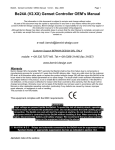
1
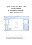
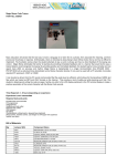
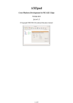
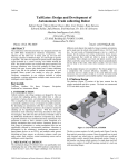
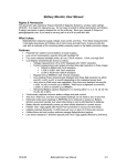
BFF Design Ltd - 64MHz Signal Processor Unit – 64SPU-1
(Firmware B)
The 64SPU-1 Signal Processor Unit is designed for use with the BFF PID Servo Controller software as part of a DIY
motion platform closed loop position feedback PID servo control system. V2.6beta96 or later of the PID Servo Controller
(V2.6beta963 for Firmware B support) and v2.6 or later of the BFF Motion Driver software are required . For details of a
typical overall system arrangement see the illustrative System Wiring Diagram at the end of this document.
IMPORTANT – THE 64SPU-1 IS INTENDED FOR USE AS PART OF A PROPERLY PROTECTED CLOSED LOOP
SERVO DRIVE. IF YOU USE THE 64SPU-1 YOU MUST ENSURE YOUR DRIVE IS FULLY PROTECTED AGAINST
UNCONTROLLED MOTOR DRIVE IN THE EVENT OF WIRING, COMPONENT OR OTHER FAULTS OCCURRING IN
YOUR SYSTEM. THIS IS ESPECIALLY IMPORTANT IN HOME-BUILT SYSTEMS. THE 64SPU-1 HAS A NUMBER OF
BUILT IN SAFETY CUTOFF FEATURES, HOWEVER IT CAN NOT DETECT ALL FAULT EVENTS THAT MIGHT OCCUR
IN A SYSTEM. YOU MUST FIT OVER-TRAVEL CUT-OFF SWITCHES TO CUT ELECTRICAL POWER TO THE MOTOR
CONTROLLERS IN THE EVENT OF ACTUATOR OVER-TRAVEL. YOU MUST ALSO FIT ONE OR MORE EMERGENCY
STOP SWITCHES IN OBVIOUS AND ACCESSIBLE POSITIONS WHICH ALSO CUT ELECTRICAL POWER TO THE
MOTOR CONTROLLERS.
NEVER MAKE ANY WIRING OR CONNECTION ADJUSTMENTS WHEN THE SERVO DRIVE IS ACTIVE AND THE
64SPU-1 IS OPERATING. ALWAYS POWER DOWN THE SYSTEM BEFORE MAKING ANY ADJUSTMENTS.
1. 64SPU-1 Features
•
I2C data output for use with Devantech MD03 motor speed controllers (I2C 400KHz Baud).
•
2 or 3 channel output for 2 or 3 DOF motion systems.
•
Selectable Potentiometer (10 bit) or MA3 Digital Encoder (12 bit) position feedback.
•
Built-in fast smoothing on the potentiometer feedback to reduce signal noise. For best potentiometer feedback
performance use the 12ADC-1 12bit converter card with the 64SPU-1 (Firmware B - requires PID Servo
Controller V2.6beta963).
•
Built-in “Pause Output” trip loop.
•
64MHz chip speed giving up to 50Hz control loop refresh speeds (PC and connection dependent). Up to 70Hz
when used with the 12ADC-1 12bit converter card.
1
•
Direct connection to PC USB or Serial port (physical serial port or USB virtual Com port with “Latency Timing” set
to 1ms recommended for fastest speeds). 115200 baud serial comms.
•
LED status and error indicators.
•
On-board 20X2 micro-controller re-programmable in situ to allow firmware upgrades or customised programming.
2. Connections and Settings
Refer to photo A) CN3-1 Position Feedback inputs. Signal connections from either potentiometer or MA3 encoders that provide
actuator position feedback for the system. To select potentiometer feedback jumper JMP-1 should be OPEN. For
MA3 encoder feedback jumper JMP-1 should be closed.
With JMP-1 open - Feedback potentiometer wipers. Use good quality 10K linear pots. The +ve direction of the
pots should match the +ve direction of rotation of the drive motors, otherwise the motor drive will be unstable.
OR
With JMP-1 closedFeedback signals from US Digital MA3 absolute position encoders. Only the 12bit PWM MA3
encoder types are supported – 10bit PWM and analogue types are NOT supported.
B) 0V & 5V supply for the feedback pots or encoders – conveniently located beside the feedback signal connections.
DO NOT drive other electrical equipment from the 5V connection on the 64SPU-1 board.
C) CN4-3 – Auxilliary Outputs, Aux Out 1 is pre-programmed as indicated below. Aux Out 2 to 4 are available for
future upgrades and may be re-programmed by advanced users to provide alternative motor controller drive
outputs. Customers can contact me for examples of 20X2 chip flash programming.
“Aux Out 1” is SyRen controller high/low enable. High for “drive”, low for “stop drive”.
D) CN4-2 – I2C outputs to the Devantech MD03 motor speed controllers. The 0V and 5V connections can be used
for the logic supply to the MD03's. Note the I2C bus wire lengths must be kept to less than approximately 300mm.
The MD03 controllers must be set to the correct I2C addresses (Actuator 1 – 0xB0, Actuator 2 – 0xB2, Actuator 3
– 0xB4, see your MD03 documentation for the correct dip switch settings for this). Your normally closed actuator
end-of-travel limit switches and an Emergency Stop switch MUST be wired in series in the 5V line to the MD03's
to power-down the controllers if the actuators over-stroke or an emergency stop is required. To make your motion
platform drive failsafe it is essential that the logic supply voltage to the motor controllers is cut when over travel
2
conditions occur. Alternative emergency cut-of arrangements can be considered, however it is essential that if
loss of motion control is suffered for whatever reason then the drive to the motors is cut. This is best achieved by
limit switches that are physically triggered by the over travel.
E) CN4-1 – Upper connection pair is a normally closed pause switch loop. If this loop goes open the drive to the
motors is cut by the 64SPU-1 and the red and green LEDS flash together. A “Pause Output” or “Drive Enable”
switch can be wired in this loop. If you don't use a Pause/Enable switch then you must wire a short loop between
the connectors to disable the trip detection.
CN4-1 – Lower connection pair provides alternative 0V and 5V power in connections for the board – see F) below
for important comments on the logic voltage power supply.
F) DC-1 – Power-in connector to suit 2.1mm power plugs – tip +ve. The board supply must be a REGULATED 5V
DC supply of at least 500mA capacity. An unregulated voltage or inadequate current capacity may result in
voltage dips which can cause the board's IC to drop out or the MD03's to mis-function. The board circuit includes
capacitors to stabilise the 5V lines however there is a limit to the level of protection this can give in the face of an
irregular logic supply voltage. NOTE the board is not fitted with inverted polarity protection – not not reverse the
polarity of the supply. It is recommended that the logic supply is separate from the main motor power supply. Do
not connect other electrical equipment to the 5V connections on the board as this might introduce disruptive
voltage spikes or dips which can affect the 64SPU-1 function.
G) G – Stereo jack socket for PC connection. You MUST use either a PICAXE AXE027 USB download cable or a
AXE026 Serial download cable. In my testing the AXE026 Serial cable results in noticeably faster refresh speeds
than the default USB cable connection however it requires a physical COM port installed on your PC – Serial PCI
cards are not expensive. The speed of the USB/Serial cable comms can be improved by changing the “Latency
Timing” of the virtual COM port to 1ms in the port's advanced settings. The USB download cable connects to a
USB port to communicate through a “virtual” serial port installed by the cable drivers – these drivers should be
provided with your AXE027 cable or downloaded from the PICAXE web site. NOTE neither cable is included with
the 64SPU-1 purchase – you must supply your own.
H) 5 Pin Jumper JMP-2 – Used to set the “operating” OR “programming” mode of the 64SPU-1 card. For normal
operation pins 2 and 3 of JMP-2 must be connected. To re-program the on-board 20X2 microcontroller pins 1 and
2 should be connected and pins 4 and 5 connected . To re-flash the chip you will need the Programming Editor
software available free from the PICAXE web site, and a .BAS program for the chip. THIS IS FOR ADVANCED
USERS ONLY.
BEFORE any attempt is made to re-flash the microcontroller the 64SPU-1 card MUST be powered-down and all
connections to the motor speed controllers disconnected.
I)
(Blank)
J) JMP-1 – Input select jumper. OPEN for potentiometer feedback input to CN3-2 or CLOSED for MA3 encoder
feedback to CN3-1. SUPPLIED CLOSED, SO REMOVE THE JUMPER LINK TO USE POTENTIOMETER
FEEDBACK.
K) Shown in the diagram are the optional socket and data LED for a UB232R mini-USB module. If fitted this module
can provide a direct USB connection to the card via a standard mini-B USB cable. NOTE these fittings are NOT
included in the standard 64SPU-1 card.
3. IMPORTANT - BFF PID Servo Controller Software Settings
Individual drive channels can enabled or disabled, and reads and writes to the I2C bus can be completely disabled
through the settings in the PID Servo Controller's PID26.cfg configuration file.
Line 29 of the PID26.cfg file contains an 8bit binary entry and the enable/disable settings are made by altering the
individual bits of the binary number.
EG Line 29 will look something like: 00111111 where bit7 is the leftmost or MSB and bit0 is the rightmost or LSB. The bit
designations are:
Bit7 (MSB)
- I2C Write Disable, =0 enable, =1 disable
Bit6
- I2C Read Disable, =0 enable, =1 disable
Bit5
- Channel 1 enable, =1 enable, =0 disable
Bit4
- Channel 2 enable, =1 enable, =0 disable
3
Bit3
- Channel 3 enable, =1 enable, =0 disable
Bit2
- MA3 Encoder 1 Direction Reverse, =1 normal, =0 reverse
Bit1
- MA3 Encoder 2 Direction Reverse, =1 normal, =0 reverse
Bit0 (LSB)
- MA3 Encoder 3 Direction Reverse, =1 normal, =0 reverse
If you are using MD03 current and temperature monitoring and/or MA3 Encoder position feedback it is necessary to
disable any channels that are not in use in your system. EG if you have a 2 DOF platform drive in which channel 1 is not
used then set bit5=0 etc. Otherwise the encoder pulse-in measurement made by the board's IC on the channel 1
feedback will timeout and the control loop refresh speed will slow to a crawl. This setting will also disable any read
attempts to a MD03 controller not present in the system which could also disrupt the 64SPU-1 operation.
Bit6 – If you are testing your comms with no MD03 controllers connected to the 64SPU-1 the I2C reads to those
controllers should be disabled. Also a small speed performance gain may be obtained in full operation if the I2C reads are
disabled completely. To do this set bit6=1. If you do this the MD03 controller current and temperature monitoring on the
PID Servo software will be disabled.
Bit7 (MSB) – If required the I2C writes to the MD03 speed controllers can be completely disabled. This is particularly
useful for testing purposes as it allows the full two-way comms between the 64SPU-1 and the PC to the checked without
risk of activating the physical drives. To disable the I2C writes set bit7=1. If I2C writes are enabled the 64SPU-1 card will
check for active MD03 controllers on the I2C bus and report an error 5 (green, amber & red LEDS flash together) if any
active controllers are not responding.
Bits0-2 – The direction of +ve feedback from MA3 encoders can be reversed by altering these bits, set =0 to reverse the
MA3's default +ve direction. NOTE the +ve direction of MA3 output can not be altered by reversing the 0 and 5V supply
as with a potentiometer.
BAUD Setting
Line 28 of the PID26.cfg file contains the baud rate setting for the serial comms to the 64SPU-1. This must be set to
115200 for the 64SPU-1 to operate with its default programming.
For other BFF Servo Controller set up information (eg PID settings and system tuning) see the BFF Motion Driver User
Manual.
4. Operation and LED Sequences
Make any settings required to the PID26.cfg config file – see section above.
Set the correct COM port number in the motion driver .bff configuration file you are using (parameter Port=COM?).
Ensure all connections are made and secure on the 64SPU-1 and the jumper setting is as required. Power-up the
64SPU-1 before starting the BFF PID Servo Controller software. When the 64SPU-1 powers-up the Amber LED will come
on followed by 2 or 3 flashes of the Green LED. 2 Green flashes indicate potentiometer feedback is selected, 3 flashes
indicate MA3 encoder feedback is enabled. If the 12ADC-1 12bit pot feedback converter card is connected the Green
LED will flash 4 times (Firmware B programming). The Amber LED will then light and the 64SPU-1 will command zero
speed from the MD03's and wait for data from the PC.
With the BFF Motion Driver v2.6 (or later) running on your PC start the PID Servo Controller software. If the comms are
operational and the 64SPU-1 is receiving data it will flash the Amber LED once and then make three flashes to indicate
the status of each channel – red for disabled, green for enabled. So for example Amber then Green – Green – Red
indicates channels 1 and 2 are enabled and channel 3 is disabled. If all channels are disabled the Red and Green LED's
will flash together to indicate an error.
Full comms between the PID Servo Controller and the 64SPU-1 should then commence and the Green LED should be
seen flickering at the servo loop refresh speed – at the higher refresh speeds the flickering may be difficult to discern.
Subsequent Error Codes are:
4
Red, Green and Amber LED's flashing together at PID Servo Controller startup. This indicates one of the active MD03's is
not responding on the I2C bus – check the wiring and 5V logic supply and the dip switch settings on the MD03's. If you
are using the I2C Isolator Card then check that this has power. The MD03 causing the fault can be identified by checking
bytes 31 (ch 1), 32 (ch 2) and 33 (ch 3) in the PID-err.log file for a 255 entry. The MD03 test consists of requesting the
current firmware version from the MD03's, at the time of writing this is 13, however a null response returns a 255 value for
the revision.
Red and Green LEDs flashing (after the initialization sequences) – Trip loop has been opened. Normally due to a Pause
Output switch being tripped (opened). If you are not using this trip loop then you may have forgotten to wire a short loop
between the two trip connectors on CN4-1. Close the loop to return to normal operation.
Occasional Amber “blinks” – these indicate solitary serial-in timeouts detected by the 64SPU-1. The 64SPU-1 will react to
sustained timeouts by closing the drive to the motors – see next item. However it is programmed to ignore single short
timeouts and try again immediately to receive data from the PC. You may notice these solitary timeout events are more
common when using the USB download cable, on my systems they are very rare when using a physical serial port
connection. Comms timeouts of duration longer than 80 ms will cause the motor drive to be cut.
Red LED flashing (with intervening green/ & amber flickers) – Sustained time-out (> 80 ms) on serial-in, the comms
between the PC and 64SPU-1 have been interrupted. This is usually because the PID Servo Software has been closed or
has stopped sending data. The green & amber flickers show the 64SPU-1's further attempts to receive data – the unit will
try to re-establish comms and will pick-up normal operation when the PID Servo Controller software re-starts. The unit is
programmed to be sensitive to loss of comms between it and the PC, this is to ensure as far as is possible that the drive
to the motors is cut if communications with the controlling PC software is interrupted or lost.
The unit may have to be powered down & back up and the PID servo Controller software restarted if repeated successive
comms interrupts occur.
Amber LED flashing – received serial data appears to be corrupted.
Red LED flashing – wrong version of PID Servo Controller software. This is to check for very old versions of the software
but will not differentiate between recent v2 versions. For the 64SPU-1 card to operate fully V2.6beta96 of the PID Servo
Controller must be used.
Red and Amber LEDs Flashing – an active feedback channel has gone to its high or low limit (eg for wiring disconnect).
Drive will be cut and remain cut. Check the feedback device wiring and connections and trace the fault before reseting the
64SPU-1. NOTE the 64SPU-1 is not able to detect a disconnect in the potentiometer wiper lines but can detect loss of 0
or 5V supply to the pots and loss of signal pulse from MA3 encoders.
Error Reports to PID Servo Controller software:
Cards running with PID Servo Controller v2.6beta96 or later will report hardware errors to the PID Servo Controller which
will be displayed on screen as a user error message.
The 64SPU-1 Firmware A error numbers are 1. Data from PC appears to be corrupted
2. No active channels defined – all the output channels may have been disabled in the PID26.cfg file – needs one at
least.
3. Wrong version of PID Servo Controller – try the most recent version available on the web site.
4. Feedback has gone out of range. One of the feedback signals has gone out of range. Check the feedback
devices and connections.
5. No response from at least one MD03 motor controller specified as active in the PID26.cfg file.
5
If a hardware error is reported a data dump is made to files PID-err.log and PID_SC.log the motion driver working
directory. These contain the values of all the data registers in the 64SPU-1 chip at the time of the error. If you need help
understanding an error the hardware is reporting then email me the PID-err.log and PID_SC.log files and I can have a
look at the data.
NOTE the card will perform a check on the MD03 motor controllers at startup – ie after it has received its start signal from
the PID Servo Controller software. If a controller specified as active is not responding on the I2C bus then an Error 5 will
be reported and the 64SPU-1 card will flash all three LED's together.
If you wish to run test the 64SPU-1 card and comms without active MD03's present then DISABLE the read and write bits
in the binary entry line in the PID26.cfg file. - see section 3 above.
5. Important Notes
Please read all of this data sheet thoroughly before using the 64SPU-1.
1. Note that v2.6 or later of the BFF Motion Driver software and v2.6beta96 or later of the BFF PID Servo Controller
Software are required for the 64SPU-1 to operate. v2.6beta963 or later of the PID Servo Controller is required for
full Firmware B features to be operational.
2. The safety of your motion platform drive system should be foremost in your mind as you build and operate your
platform. Carefully consider the limit switch requirements discussed in section 2. D) above. Carefully consider the
provision of prominent and accessible Emergency Stop buttons/switches.
3. Never make any wiring or connection adjustments when the servo drive is active and the 64SPU-1 is operating.
Always power down the system before making any adjustments. If you are also using the BFF I2C Isolator card
make sure that also is powered down before attempting any hardware adjustments.
4. Carefully consider the 5V power supply requirements described in section 2. F) above. An inadequate or
unregulated 5V power supply will cause problems with the 64SPU-1 function.
5. Do not power other electrical equipment from the 64SPU-1 power connections. Also, use a dedicated battery
supply for the MD03 motor speed controllers driven by the 64SPU-1 card. If other equipment is also supplied by
the battery supply and that equipment is connected to the same PC by its own USB or serial connection then a
ground loop can be formed. This can induce large currents to flow through the 40SPU serial/USB cable which will
disrupt the communications and potentially damage the card.
6. Ensure all connections to the feedback potentiometers or encoders are absolutely secure. Erratic feedback
signals can be caused by intermittent connections on any of the feedback device power or signal lines, and
erratic feedback positions will cause the servo drive to react erratically. Loss of position feedback when the drive
is in operation may result in fast drive to the actuator end stops. The 64SPU-1 includes some feedback signal
loss detection on MA3 encoder input and due to loss of 0V or 5V connections to the potentiometers. However this
will not protect from erratic feedback due to loose connections in the potentiometer wiper lines or from some
types of intermittent wiring faults. Make sure all connections and wiring are secure.
7. During your initial system set up and testing set the I2C Write Disable bit (bit7) in the PID26.cfg to 1 to disable all
writes to the MD03 speed controllers – as described in section 3 above. This will allow you to check your system
wiring, position feedback function, comms etc without activation of the drive motors. Alternatively remove the
main power fuses to ensure no power is available for the motors.
8. It is recommended that initial set up and testing of the servo drive hardware and system be undertaken with the
drive actuators mechanically disconnected from the motion platform. This will allow the stability of the electric
6
motor motion output to be assessed without risk of damage to the platform.
9. On testing I originally found that the best servo drive performance was obtained using US Digital MA3 absolute
position encoder input for position feedback and connection to a physical Serial “COM” port on the PC. The MA3
encoders exhibit lower noise levels than potentiometers and allow sharper gains to be used in the PID Servo
Controller settings. The Physical COM port connection appears to allow faster servo loop refresh speeds than
comms through the USB “virtual” COM port and these higher loop speeds also improve the motion quality. Note
that only the 12bit PWM MA3 encoder types are supported and that they have a single turn 360 degree electrical
travel – not the multi-turn capability of some potentiometers. This may affect the physical location of their fitment
on
the
platform.
However MA3 levels of feedback performance can now be obtained from potentiometers using the newly
available 12ADC-1 12bit potentiometer feedback converter card. This requires Firmware B programming of the
64SPU-1. Also the speed of USB/Serial cable comms can be raised by adjusting the “Latency Timing” setting of
the virtual COM port to 1ms. This can be done in the COM port's advanced settings accessible through the
windows Device Manager.
6. Revision History
Firmware A – June 2010, first release.
Firmware B – August 2010, added support for the 12ADC-1 12bit potentiometer feedback converter card. Requires PID
Servo Controller v2.6beta963 or later.
Feb 2011 – Updated data sheet to 1.2 for Rev 2 cards with UB232R USB module provision.
To upgrade the firmware on your 64SPU-1 card please email me at [email protected] for the latest firmware program
and instructions.
7
Typical Overall System Wiring
Ian Hopper (BFF Design Ltd), 64SPU-1 Data Sheet Rev 1.20
© 2009, 2010, 2011 BFF Design Ltd – All Rights Reserved
8
Appendix 1
64SPU-1 Servo system set-up checks (with MD03's).
This appendix outlines a series of checks to confirm the proper set up and operation of the 64SPU-1
card and servo system. A motion platform closed loop servo drive is a relatively complicated system
and it is strongly recommend that a step-by-step process is taken to setting up and commissioning
the card and system. In this way proper operation can be confirmed at each stage prior to final
loaded operation of the system and any set-up issues more easily identified and addressed along the
way.
1. 64SPU-1 Check 1 – PC-Card Serial Comms
Configuration
•
Connect at least one feedback pot or encoder to the 64SPU-1 card CN3-1 and set jumper
JMP-1 to suit the feedback device type (pot or MA3 encoder). DO NOT mechanically connect
the feedback device to the actuator or platform. Move the pots/encoder shafts to a roughly mid
position
•
Bypass the trip loop on CN4-1
•
Connect the card to the PC with suitable download cable
•
DO NOT connect anything to the I2C connector CN4-2 on the card (no SDA, SCL, 0 or 5V)
•
Disable any unused feedback channels using the binary settings in the PID26.cfg file (see
section 3 of the 64SPU-1 data sheet)
•
Disable both I2C Read and Write using the binary settings in the PID26.cfg file (in the binary
number entry set bits 6 & 7 = 1)
•
Connect 5V and ground logic supply to the card and check the power-up LED sequence is
correct (see section 4 of the data sheet).
Test
With a flight sim active start the motion driver with your working .bff configuration file. Start the PID
Servo Controller software from the motion driver window. If the 64SPU-1 card is powered up and
operational and the serial comms are running properly you should see the card go through its
initialisation LED sequence (data sheet section 4) ending with the green LED flickering very quickly at
the servo loop refresh frequency.
Is it doing this? Is the PID servo controller refresh speed reported by the software good and steady?
Allow the comms to run for a while and monitor the card for yellow or red LED activity.
If the PID Servo Controller runs but the card does not respond with its "active channel" LED
sequence and green LED flickering then the software should report a comms time-out. There is a
problem with the serial comms – check the COM port number in the .bff config file, the baud setting in
the PID26.cfg file and your cable connections. Try an alternative port, or try it on an alternative PC to
9
try and narrow down the problem.
If the servo loop is active then manually move one of the feedback device positions and check that
the position feedback is being reported in the PID Servo Controller window smoothly and
continuously. Check each active feedback channel.
If there is no movement reported then check the feedback device connections and the devices
themselves.
Open the "Actuator Details" window on the PID Servo Controller for an active channel so that you can
see both the demanded and actual actuator position bars. Move the feedback position pot/encoder
manually to bring the position feedback towards the position demand. As the actual position
approaches the demanded position you should see the speed demand output reduce to zero as the
position error reduces to zero. Whether or not the speed demand stays at zero depends on your PID
settings and in particular the I setting – see section 5.3 of the Motion Drive user manual.
If this all works satisfactorily then you can go on to check the trip loop function by momentarily
breaking the trip loop connections (you should see red and green LED's flashing together).
If you are using feedback potentiometers then check the "out of range" trip by moving one
potentiometer to the end of its electrical travel – red and amber LED's should flash together.
If you are using MS3 position encoders then check the loss of pulse trip by momentarily
disconnecting one of the MA3 encoders from connector CN3-1.
If all this works properly then go on to the next test.
10
2. Check 2 – MD03 motor controller I2C READ comms checks
Configuration
As for Check 1 above with feedback devices connected and trip loop by-passed, and additionally:
•
Power-down the 64SPU-1
•
Connect the MD03 motor controllers for the active channels to CN4-2 on the card. Make sure
the connected MD03's have the correct dip switch settings for their actuator numbers.
•
DO NOT make ANY connections to the high current motor/24V supply end of the MD03's.
•
In the PID26.cfg file enable I2C Read only (bit 6 = 0) – DO NOT enable I2C write at this stage.
Test
Power up the 64SPU-1 and start the motion driver and PID Servo Controller as before.
Confirm that the operation of the servo loop as reported by the software and the 64SPU-1 LED's is
normal and steady. You should be able to see some minimal activity in the Current and Temperature
read-back bars in the PID Servo Controller window. If so this indicates that the 64SPU-1 has found
the MD03's and is successfully reading their I2C data registers. You will expect to see a very slight
increase in the servo loop refresh time reported by the software.
Check the security of the I2C wiring between the MD03's and the card – make sure moving the wires
slightly does not interrupt the servo loop operation.
If the servo loop is very much slower and/or erratic than there may be a problem with the I2C comms
– check the MD03 connections to the card, check that 5V is getting to the MD03 logic voltage input.
Check that the dip switch settings match the active output channel settings of the system (ie that the
card is not trying to read data from a non-existing I2C address). Make sure that your I2C lines are
short (no longer than say 200mm).
If all is well go on to Check 3 to start to check the I2C write comms.
11
3. Check 3 – MD03 motor controller I2C WRITE comms checks – stage-1
Configuration
As for Check 2 above with feedback devices connected and trip loop by-passed, and additionally:
•
Power-down the 64SPU-1
•
DO NOT make ANY connections to the high current motor/24V supply end of the MD03's.
•
In the PID26.cfg file enable I2C Write (bit 7 = 0)
Test
Power up the 64SPU-1 and start the motion driver and PID Servo Controller as before.
Confirm that the servo loop is operating normally and steadily.
This stage 1 check is to confirm that I2C writes to the MD03's does not disrupt the servo loop
operation.
If this is so – move on to Check 3 – stage 2.
12
4. Check 3 – MD03 motor controller I2C WRITE comms checks – stage-2
Configuration
As for Check 3-1 above with feedback devices connected and trip loop by-passed, and additionally:
•
Power-down the 64SPU-1
•
Connect your 24V power supply to the high current +V and GND connectors at the motor/24V
supply end of the MD03's. DO NOT connect your motors to the MD03's at this stage.
•
DO NOT connect any other equipment to the 24V power supply – especially equipment that is
connected by its own USB or Serial connections to the PC
Test
Power up the 64SPU-1 and start the motion driver and PID Servo Controller as before.
Confirm that the servo loop is operating normally and steadily.
This stage 2 check is to confirm that the main power connections to the MD03's do not disrupt the
servo loop operation.
The voltage across the MD03 motor connectors can also be checked at this stage – confirm the
motor connector voltage varies in magnitude and reverses polarity as the feedback pots are manually
adjusted to bring the feedback position close to the demanded position and the speed demand output
of the PID Servo Controller varies.
If this is so – move on to Check 3 – stage 3. First adjust the feedback pot positions to set the
feedback positions equal to the demanded positions with the PID Servo Controller in "Hold" mode.
This is to ensure in the next test there is minimal speed demand when the software and servo loop is
powered up.
13
5. Check 3 – MD03 motor controller I2C WRITE comms checks – stage-3,
motor run test.
Warning
From this stage on the system checks involve applying voltage to the drive motors. This will result in
drive output from the motor shafts. ENSURE THAT ALL PRECAUTIONS ARE TAKEN TO
PROPERLY SECURE THE MOTORS AND PROTECT PERSONNEL AND EQUIPMENT FROM
INJURY OR DAMAGE.
Configuration
As for Check 3-2 above with feedback devices connected and trip loop by-passed, and additionally:
•
Power-down the 64SPU-1 and MD03's
•
Connect your drive motors to the MOT connectors at the motor/24V supply end of the MD03's.
DO NOT mechanically connect the motors to the platform – their output shafts must be free to
rotate unloaded. ENSURE the motors are securely held down on a work bench or similar.
ENSURE their output shafts are guarded to prevent accidental contact with personnel or
equipment.
•
Re-connect the 24V power supply to the MD03's.
Test
This stage 3 check is to confirm the unloaded operation of the drive motors.
Power up the 64SPU-1 and start the motion driver and PID Servo Controller as before.
Confirm that the servo loop is operating normally and steadily.
Confirm that the motor output shaft speed varies in magnitude and reverses direction as the feedback
pots are manually adjusted to vary the error between the feedback position and the demanded
position – ie as the speed demand output of the PID Servo Controller varies with the position error
changes.
Switching the PID Servo Controller to "Drive" mode with the Motion Driver still on "Hold" mode will
allow the position error to be adjusted to generate the maximum speed demand output – ie maximum
motor drive speed.
Monitor the servo system for signs of interruptions as the motors are running – check for amber or
red LED flashes, or erratic servo loop refresh times or time-out messages on the PID Servo
Controller. If these are present while the motors are running then the system may be affected by
electrical noise from the motors or fluctuations in the logic supply to the 64SPU-1 card and MD03's.
Make sure noise reduction capacitors are fitted to the motors as described in the MD03
documentation. Make sure your 5V logic supply is regulated and of adequate current capacity.
14
In preparation for further testing adjust the feedback pot positions to set the feedback positions equal
to the demanded positions with the PID Servo Controller in "Hold" mode to minimise the speed
demand output from the PID software.
15
6. Check 4 – Closed Servo Loop Test.
Configuration
As for Check 3-3 above with feedback devices connected and trip loop by-passed, and additionally:
•
Power-down the 64SPU-1 and MD03's
•
Mechanically fit the feedback pots/encoders to the motors so that they correctly report the
physical rotation of the drive. This may need mechanical elements of the actuator drives to be
assembled so that the pots can be mounted properly. It is best if this test is carried out with the
actuators unloaded – ie not driving the weight of the motion platform. This will reduce the
potential for equipment damage should the servo loop become unstable.
•
The pots should be fitted so that they operate comfortably within their electrical travel range
when the actuator strokes over its full mechanical travel. They should also be fitted so that
their +ve electrical rotation matches the +ve direction of drive of the actuator motors. If this is
not the case then the servo loop will drive the motors in the opposite direction to that required
to close the position error and the system will drive hard against its end stops.
•
If necessary fit over-stoke cut-off switches to the actuators to protect against uncontrolled drive
of the motors.
•
ENSURE all equipment is properly secured and guarded to prevent injury or damage to
personnel or equipment.
•
Re-connect the 24V power supply to the MD03's.
Test
This check is to confirm the unloaded operation of the closed loop servo drive.
Power up the 64SPU-1 and start the motion driver and PID Servo Controller as before.
When the 64SPU-1 starts the servo loop it will generate a demanded motor speed in the direction
required to close any existing position error. If the pots have the correct electrical sense then the
motor direction of rotation should reduce the position error and the motors will drive to and stop at the
demanded position. If the pot sense is wrong then the motor will drive at speed to the end stops – in
this case reverse the pot +ve direction of rotation, or reverse the motor +ve direction of rotation, or, in
the case of MA3 encoders reverse the encoder +ve direction of rotation by adjusting bits 0 to 2 in the
PID26.cfg binary entry.
Confirm that the servo loop is operating normally and steadily.
If operation is correct then the motor position will follow adjustments made to the position demand
output of the motion driver – either using the "Manual Adjustment" button features, by making a flight
sim active, or by using the Joystick Input mode (requires motion driver v2.6 or later).
If the servo loop is stable you can experiment with the PID servo loop settings for the actuators – see
16
section 5.3 of the motion driver user manual.
Once this check has been completed the basic unloaded operation of the servo drive will have been
confirmed and subsequent stages of assembly and commissioning of your motion platform can be
tackled.
17