1
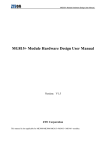
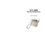
GSM-MG3431 module product
ZTE MG3431 Module Technical Specifications
Version:V1.0
GSM-MG3431 module products
Copyright Statement
Copyright © 2008 by ZTE Corporation
The copyright of this User Manual belongs to ZTE Corporation and under the protection of Copyright
Law of the People’s Republic of China and other relative laws.
No part of this publication may be excerpted,reproduced, translated or utilized in any form or by any
means (electronic or mechanical , including photocopying and microfilm) without prior written
permission from ZTE Corporation. Any violation behavior will be punished.
The information in the document is subject to change without notice. At the same time we reserve the
right to revise or recall the User Manual.
If there is anything unclear in this manual, please contact us or our agent or seller.
V4.9-TY, Feb.2008
1
GSM-MG3431 module products
With strong technical force, ZTE Corporation can provide CDMA/GPRS module customers with the
following all-around technical support:
1. Provide complete technical documentation;
2. Provide the development board used for R&D, test, production, after-sales, etc.;
3. Provide evaluations and technical diagnosis for principle diagram, PCB, test scenarios;
4. Provide test environment;
ZTE Corporation provides customers with onsite supports, and also you could get supports through
telephone, website, instant communication, E-mail, etc.
The module website http://module.ztemt.com.cn provides the relevant industry information and
module technical documentation. The authorized module customers could download the latest
technical documentation for our website. If you have more requirements, you could send an E-mail to
[email protected]. You can also call us at 0755-86360280 for more supports.
2
GSM-MG3431 module products
Foreword
Summary
The corresponding product to this document is MG3431 module. It introduces the appearance,
hardware framework, functions and technical specifications of MG3431, which is used for supporting
design reference to hardware engineers and product designers.
Object readers
This document is mostly suitable for engineers as below:
z System designers
z Product engineers
z Hardware engineers
z Software engineers
z Test engineers
Brief
This document contains 6 chapters, as following:
Chapter
Contents
1Summary
Background, concepts and applications of MG3431
2 Abbreviation
Abbreviations appeared in this document
3 Appearance and framework
Appearance figure of MG3431 module
4 Functions
Basic functions of MG3431 module
5 Interfaces
Basic interfaces of MG3431 module
6 Technical specifications
Introduce particular technical specifications of MG3431 module
Modified records
Modified records accumulate update notes every time. The latest document version includes all
update contents previously.
Document version V1.0 (2008-06-03)
Released formally for the 1st time
3
GSM-MG3431 module products
Table of contents
1 SUMMARY ....................................................................................................................................... 7
2 ABBREVIATION ............................................................................................................................... 7
3 APPEARANCE AND FRAMEWORK ................................................................................................ 8
4 FUNCTIONS .................................................................................................................................... 9
5 INTERFACES ................................................................................................................................... 9
6 TECHNICAL SPECIFICATIONS..................................................................................................... 10
6.1 TECHNICAL PARAMETERS ............................................................................................................ 10
6.2 RF SPECIFICATIONS.................................................................................................................... 10
6.3 RECOMMENDATION OF ANTENNA SPECS ....................................................................................... 10
6.4 POWER SUPPLY.......................................................................................................................... 11
6.5 WORKING CONDITIONS ............................................................................................................... 11
4
GSM-MG3431 module products
Table of figures
Figure 3-1 Appearance of MG3431 module..........................................................................................9
5
GSM-MG3431 module products
Tables
Table 4-1 Main functions and features..................................................................................................9
Table 5-1 Interfaces of the modules......................................................................................................9
Table 6-1 Technical parameters..........................................................................................................10
Table 6-2 RF specifications parameters .............................................................................................10
Table 6-3 Recommended antenna specs ...........................................................................................10
Table 6-4 Input voltage ....................................................................................................................... 11
6
GSM-MG3431 module products
1 Summary
ZTE MG3431 module is the EDGE wireless module, with abundant voice, SMS and data service
functions. The modules can be applied in handsets, wireless data cards, USB modem, trackers, etc.
This document introduces the appearance, hardware framework, functions, technical specifications
and relevant test standards for MG3431 module in detail.
2 Abbreviation
Abbr.
ADC
Full name
Analog-Digital Converter
AFC
Automatic Frequency Control
AGC
Automatic Gain Control
ARFCN
Absolute Radio Frequency Channel Number
ARP
Antenna Reference Point
ASIC
Application Specific Integrated Circuit
BER
Bit Error Rate
BTS
Base Transceiver Station
CDMA
Code Division Multiple Access
CDG
CDMA Development Group
CS
Coding Scheme
CSD
Circuit Switched Data
CPU
Central Processing Unit
DAI
Digital Audio interface
DAC
Digital-to-Analog Converter
DCE
Data Communication Equipment
DSP
Digital Signal Processor
DTE
Data Terminal Equipment
DTMF
Dual Tone Multi-Frequency
DTR
Data Terminal Ready
EDGE
Enhanced Data rate for GSM Evolution
EFR
Enhanced Full Rate
EGSM
Enhanced GSM
EMC
Electromagnetic Compatibility
EMI
Electro Magnetic Interference
ESD
Electronic Static Discharge
ETS
European Telecommunication Standard
FDMA
Frequency Division Multiple Access
FR
Full Rate
GPRS
General Packet Radio Service
7
GSM-MG3431 module products
GSM
Global Standard for Mobile Communications
HR
Half Rate
IC
Integrated Circuit
IMEI
International Mobile Equipment Identity
ISO
International Standards Organization
ITU
International Telecommunications Union
LCD
Liquid Crystal Display
LED
Light Emitting Diode
MCU
Machine Control Unit
MMI
Man Machine Interface
MS
Mobile Station
PCB
Printed Circuit Board
PCL
Power Control Level
PCS
Personal Communication System
PDU
Protocol Data Unit
PLL
Phase Locked Loop
PPP
Point-to-point protocol
RAM
Random Access Memory
RF
Radio Frequency
ROM
Read-only Memory
RMS
Root Mean Square
RTC
Real Time Clock
SIM
Subscriber Identification Module
SMS
Short Message Service
SRAM
Static Random Access Memory
TA
Terminal adapter
TDMA
Time Division Multiple Access
TE
Terminal Equipment also referred it as DTE
UART
Universal asynchronous receiver-transmitter
UIM
User Identifier Management
USB
Universal Serial Bus
VSWR
Voltage Standing Wave Ratio
ZTE
ZTE Corporation
3 Appearance and framework
Appearance of MG3431 is as following figure 3-1:
8
GSM-MG3431 module products
Figure 3-1 Appearance of MG3431 module
z
z
Dimension(length x width x height):34.5mm x 26.0mm x 2.5mm
Weight:5g
4 Functions
Please refer to Table 4-1 for the main functions and features.
Table 4-1 Main functions and features
Item
Description
Data
EDGE data service
Voice
High-quality voice
SMS
Support TEXT and PDU
5 Interfaces
Please refer to Table 5-1 for the Interfaces.
Table 5-1 Interfaces of the module
Item
Description
UART interface
Download software to update
Data communication
Maximum data rate 460kbps through the port
Audio interface
Audio I/O channel
SIM card interface
SIM card interface
Antenna interface
50 Ohm input impedance control
USB interface
USB2.0 Device, support full speed (480Mbps)
9
GSM-MG3431 module products
6 Technical specifications
6.1 Technical parameters
Please refer to Table 6-1 for the Technical parameters
Table 6-1 Technical parameters
Item
Description
Working temperature
-20°C ~ +55°C
Input voltage
3.3V-4.25V
Maximum current
1800mA @ -102 dBm/EGSM900
Idle current
17.5mA @ -75 dBm/EGSM900
Call current
110mA @ -75 dBm/EGSM900
Low power current
8mA
6.2 RF specifications
Please refer toTable 6-2 for the RF specifications parameters
Table 6-2 RF specifications parameters
Item
GSM 900MHz frequency band
DCS 1800MHz frequency band
Tx frequency band
880~915MHz
1710~1785MHz
Rx frequency band
925~960MHz
1805~1880MHz
Output power EDGE
500mW (+27dBm)
400mW (+26dBm)
Output power GSM
2W (+33dBm)
1W (+30dBm)
Sensitivity
Less than -102dBm
EDGE encoding
Support MCS1~MCS9
EDGE rate
EDGE CLASS10
Download speed is 236.8Kbps
Upload speed is 118.4 kbps
EDGE rate
GPRS encoding
Support CS1~CS4
GPRS encoding
GPRS rate
CLASS12 rate is 120 kbps
GPRS rate
Frequency error
Less than 0.1 PPM
Frequency error
6.3 Recommendation of antenna specs
The recommended antenna specs are as following table 6-3:
Table 6-3 Recommended antenna specs
VSWR
1.5:1 maximum
Gain
At least 0 dBi in one direction
Input impedance
50Ω
Polarized form
Vertical polarizing
The requirements for antenna’s gain are different in different environment. Commonly, in used
10
GSM-MG3431 module products
frequency range, the larger gain, the better capability; otherwise, out of this range, the smaller gain,
the better capability.
6.4 Power supply
The input voltage is shown in table 6-4:
Table 6-4 Input voltage
State
Max. voltage
Typical voltage
Min. voltage
Power supply
4.25 VDC
3.90 VDC
3.30 VDC
6.5 Working conditions
z
z
z
Working temperature: -20℃ ~ +55℃
Storage temperature: -40℃ ~ +70℃
Humidity: 5% ~ 95%
11