1
EZ-ETHERNET / EZ-ETHERPLUS
Card Installation and User Manual
WARNING Thank you for purchasing automation equipment from Automationdirect.com™. We want
your new automation equipment to operate safely. Anyone who installs or uses this equipment
should read this publication (and any other relevant publications) before installing or
operating the equipment.
To minimize the risk of potential safety problems, you should follow all applicable local and
national codes that regulate the installation and operation of your equipment. These codes
vary from area to area and usually change with time. It is your responsibility to determine
which codes should be followed, and to verify that the equipment, installation, and operation
is in compliance with the latest revision of these codes.
At a minimum, you should follow all applicable sections of the National Fire Code, National
Electrical Code, and the codes of the National Electrical Manufacturer's Association (NEMA).
There may be local regulatory or government offices that can also help determine which
codes and standards are necessary for safe installation and operation.
Equipment damage or serious injury to personnel can result from the failure to follow all
applicable codes and standards. We do not guarantee the products described in this
publication are suitable for your particular application, nor do we assume any responsibility
for your product design, installation, or operation.
Our products are not fault-tolerant and are not designed, manufactured or intended for use or
resale as on-line control equipment in hazardous environments requiring fail-safe
performance, such as in the operation of nuclear facilities, aircraft navigation or
communication systems, air traffic control, direct life support machines, or weapons systems,
in which the failure of the product could lead directly to death, personal injury, or severe
physical or environmental damage ("High Risk Activities"). Automationdirect.com™
specifically disclaims any expressed or implied warranty of fitness for High Risk Activities.
For additional warranty and safety information, see the Terms and Conditions section of our
catalog. If you have any questions concerning the installation or operation of this equipment,
or if you need additional information, please call us at 770-844-4200.
This publication is based on information that was available at the time it was printed. At
Automationdirect.com™ we constantly strive to improve our products and services, so we
reserve the right to make changes to the products and/or publications at any time without
notice and without any obligation. This publication may also discuss features that may not be
available in certain revisions of the product.
Trademarks
This publication may contain references to products produced and/or offered by other
companies. The product and company names may be trademarked and are the sole property
of their respective owners. Automationdirect.com™ disclaims any proprietary interest in the
marks and names of others.
Copyright 2003, Automationdirect.com™ Incorporated
All Rights Reserved
No part of this manual shall be copied, reproduced, or transmitted in any way without the
prior, written consent of Automationdirect.com™ Incorporated. Automationdirect.com™
retains the exclusive rights to all information included in this document.
AVERTISSEMENT Nous vous remercions d'avoir acheté l'équipement d'automatisation de Automationdirect.comMC.
Nous tenons à ce que votre nouvel équipement d'automatisation fonctionne en toute sécurité. Toute
personne qui installe ou utilise cet équipement doit lire la présente publication (et toutes les autres
publications pertinentes) avant de l'installer ou de l'utiliser.
Afin de réduire au minimum le risque d'éventuels problèmes de sécurité, vous devez respecter tous
les codes locaux et nationaux applicables régissant l'installation et le fonctionnement de votre
équipement. Ces codes diffèrent d'une région à l'autre et, habituellement, évoluent au fil du temps. Il
vous incombe de déterminer les codes à respecter et de vous assurer que l'équipement, l'installation
et le fonctionnement sont conformes aux exigences de la version la plus récente de ces codes.
Vous devez, à tout le moins, respecter toutes les sections applicables du Code national de
prévention des incendies, du Code national de l'électricité et des codes de la National Electrical
Manufacturer's Association (NEMA). Des organismes de réglementation ou des services
gouvernementaux locaux peuvent également vous aider à déterminer les codes ainsi que les normes
à respecter pour assurer une installation et un fonctionnement sûrs.
L'omission de respecter la totalité des codes et des normes applicables peut entraîner des dommages
à l'équipement ou causer de graves blessures au personnel. Nous ne garantissons pas que les produits
décrits dans cette publication conviennent à votre application particulière et nous n'assumons aucune
responsabilité à l'égard de la conception, de l'installation ou du fonctionnement de votre produit.
Nos produits ne sont pas insensibles aux défaillances et ne sont ni conçus ni fabriqués pour
l'utilisation ou la revente en tant qu'équipement de commande en ligne dans des environnements
dangereux nécessitant une sécurité absolue, par exemple, l'exploitation d'installations nucléaires, les
systèmes de navigation aérienne ou de communication, le contrôle de la circulation aérienne, les
équipements de survie ou les systèmes d'armes, pour lesquels la défaillance du produit peut
provoquer la mort, des blessures corporelles ou de graves dommages matériels ou
environnementaux («activités à risque élevé»). La société Automationdirect.comMC nie toute
garantie expresse ou implicite d'aptitude à l'emploi en ce qui a trait aux activités à risque élevé.
Pour des renseignements additionnels touchant la garantie et la sécurité, veuillez consulter la section
Modalités et conditions de notre documentation. Si vous avez des questions au sujet de l'installation
ou du fonctionnement de cet équipement, ou encore si vous avez besoin de renseignements
supplémentaires, n'hésitez pas à nous téléphoner au 770-844-4200.
Cette publication s'appuie sur l'information qui était disponible au moment de l'impression. À la
société Automationdirect.com, nous nous efforçons constamment d'améliorer nos produits et
services. C'est pourquoi nous nous réservons le droit d'apporter des modifications aux produits ou
aux publications en tout temps, sans préavis ni quelque obligation que ce soit. La présente
publication peut aussi porter sur des caractéristiques susceptibles de ne pas être offertes dans
certaines versions révisées du produit.
Marques de commerce
La présente publication peut contenir des références à des produits fabriqués ou offerts par d'autres
entreprises. Les désignations des produits et des entreprises peuvent être des marques de commerce
et appartiennent exclusivement à leurs propriétaires respectifs. Automationdirect.comMC nie tout
intérêt dans les autres marques et désignations.
Copyright 2003, Automationdirect.com™ Incorporated
Tous droits réservés
Nulle partie de ce manuel ne doit être copiée, reproduite ou transmise de quelque façon que ce soit
sans le consentement préalable écrit de la société Automationdirect.com™ Incorporated.
Automationdirect.com™ conserve les droits exclusifs à l'égard de tous les renseignements contenus
dans le présent document.
EZ-Ethernet Card
Installation and
User Manual
Please include the Manual Number and the Manual Issue, both shown below, when
communicating with us regarding this publication.
Manual Number:
EZ-ETHERNET-M
Issue:
First Edition, Rev. D
Issue Date:
1/27/04
Publication History
Issue
Date
First Edition
5/15/02
Description of Changes
Original
Revision A
6/20/03
Addition of Appendix B
Updated screen captures
Added new information for Modbus TCP/IP setup and configuration
Minor corrections and additions throughout
Revision B
9/30/03
Minor corrections and additions throughout
Revision C
11/24/03
Minor corrections and additions throughout
Revision D
1/27/04
Minor corrections to Appendix B
TABLE OF CONTENTS
Chapter 1: Getting Started . . . . . . . . . . . . . . . . . . .1–1
Manual Overview . . . . . . . . . . . . . . . . . . . . . . . . . . . . . . . . . . . . . . .1–2
Overview of this Publication . . . . . . . . . . . . . . . . . . . . . . . . . . . . . . . . . . . . . . . . . . . .1–2
Technical Support . . . . . . . . . . . . . . . . . . . . . . . . . . . . . . . . . . . . . . . . . . . . . . . . . . . .1–2
Special Symbols . . . . . . . . . . . . . . . . . . . . . . . . . . . . . . . . . . . . . . . . . . . . . . . . . . . . .1–2
Overview of the EZ-Ethernet Card . . . . . . . . . . . . . . . . . . . . . . . . . . .1–2
Operating System . . . . . . . . . . . . . . . . . . . . . . . . . . . . . . . . . . . . . . . . . . . . . . . . . . . .1–3
Packing List . . . . . . . . . . . . . . . . . . . . . . . . . . . . . . . . . . . . . . . . . . . .1–3
Minimum Required Hardware . . . . . . . . . . . . . . . . . . . . . . . . . . . . . .1–4
Minimum Required Software/Firmware . . . . . . . . . . . . . . . . . . . . . . .1–4
Typical EZ-Ethernet System . . . . . . . . . . . . . . . . . . . . . . . . . . . . . . . .1–5
Installing the EZ-Ethernet Card . . . . . . . . . . . . . . . . . . . . . . . . . . . . .1–6
Chapter 2: Setting Up & Using the EZ-Ethernet . . .2–1
Setting Up Your EZ-Ethernet System . . . . . . . . . . . . . . . . . . . . . . . . .2–2
DIP Switch Settings . . . . . . . . . . . . . . . . . . . . . . . . . . . . . . . . . . . . . .2–2
Diagnostic LEDs . . . . . . . . . . . . . . . . . . . . . . . . . . . . . . . . . . . . . . . . .2–4
Status Indicator . . . . . . . . . . . . . . . . . . . . . . . . . . . . . . . . . . . . . . . . . . . . . . . . . . . . . .2–4
Link Good Indicator . . . . . . . . . . . . . . . . . . . . . . . . . . . . . . . . . . . . . . . . . . . . . . . . . .2–4
Link Active Indicator . . . . . . . . . . . . . . . . . . . . . . . . . . . . . . . . . . . . . . . . . . . . . . . . . .2–4
Error Indicator . . . . . . . . . . . . . . . . . . . . . . . . . . . . . . . . . . . . . . . . . . . . . . . . . . . . . . .2–4
Tutorials . . . . . . . . . . . . . . . . . . . . . . . . . . . . . . . . . . . . . . . . . . . . . .2–5
Tutorial A: First Time Connection . . . . . . . . . . . . . . . . . . . . . . . . . . .2–5
Tutorial B: Adding PLCs to Your Project . . . . . . . . . . . . . . . . . . . . . .2–15
Tutorial C: Adding a Second EZTouch Panel . . . . . . . . . . . . . . . . . .2–20
EZ-Ethernet Firmware Upgrade Instructions . . . . . . . . . . . . . . . . . . .2–24
The EZ-Touch Panel Configuration Window . . . . . . . . . . . . . . . . . .2–26
The NetEdit Window . . . . . . . . . . . . . . . . . . . . . . . . . . . . . . . . . . . .2–27
Table of Contents
Appendix A: Specifications & Error Codes . . . . . .A–1
EZ-Ethernet Card Specifications . . . . . . . . . . . . . . . . . . . . . . . . . . .A–2
Ethernet Cable . . . . . . . . . . . . . . . . . . . . . . . . . . . . . . . . . . . . . . . .A–3
EZ-Ethernet Error Code Descriptions . . . . . . . . . . . . . . . . . . . . . . .A–3
Appendix B: EZ-ETHERPLUS . . . . . . . . . . . . . . . . .B–1
Introduction . . . . . . . . . . . . . . . . . . . . . . . . . . . . . . . . . . . . . . . . . .B–2
Configuring MODBUS/TCP Nodes . . . . . . . . . . . . . . . . . . . . . . . . .B–3
Things to Remember . . . . . . . . . . . . . . . . . . . . . . . . . . . . . . . . . . .B–9
ii
EZ-Ethernet Card Installation and User Manual
1st Ed. Rev. D
1/04
GETTING STARTED
CHAPTER
1
In This Chapter...
Manual Overview . . . . . . . . . . . . . . . . . . . . . . . . .1–2
Overview of the EZ-Ethernet Card . . . . . . . . . . . . .1–2
Packing List . . . . . . . . . . . . . . . . . . . . . . . . . . . . . .1–3
Minimum Required Hardware . . . . . . . . . . . . . . . .1–4
Minimum Required Software/Firmware . . . . . . . . .1–4
Typical EZ-Ethernet System . . . . . . . . . . . . . . . . . .1–5
Installing the EZ-Ethernet Card . . . . . . . . . . . . . . .1–6
Chapter 1: Getting Started
Manual Overview
Overview of this Publication
The EZ-Ethernet Installation and User Manual describes the installation and
configuration of the EZ-Ethernet Card. Refer also to the EZ-Touch software and
Hardware manuals, the PLC manual, and the Ethernet Communications Module
manual.
Technical Support
By Telephone: 770-844-4200
(Mon.-Fri., 9:00 a.m.-6:00 p.m. E.T.)
On the Web: www.automationdirect.com
Our technical support group is glad to work with you in answering your
questions. If you cannot find the solution to your particular application, or, if for
any reason you need additional technical assistance, please call technical support
at 770-844-4200. We are available weekdays from 9:00 a.m. to 6:00 p.m. Eastern
Time.
We also encourage you to visit our web site where you can find technical and
non-technical information about our products and our company. Visit us at
www.automationdirect.com.
Special Symbols
When you see the “notepad” icon in the left-hand margin, the paragraph to its
immediate right will be a special note.
When you see the “exclamation mark” icon in the left-hand margin, the paragraph to
its immediate right will be a WARNING. This information could prevent injury, loss of
property, or even death (in extreme cases).
Overview of the EZ-Ethernet Card
The EZ-Ethernet Option Card provides a low-cost, high performance Ethernet link
between one or more EZTouch control panels and corresponding Koyo DL205 or
DL405 systems. The EZEthernet Option Card installs directly inside the EZTouch
panel.
Ethernet communications requires one or more Ethernet Communications
Modules (ECOM) be installed in the local base of the PLC system. When
connected to a live 10BaseT network, the EZEthernet Option Card acts as a
conduit to pass control packets between the EZTouch Panel and PLC system(s).
The EZ-Ethernet Option Card allows a single panel to communicate with up to ten
unique with up to ten unique DirectLogic or Modbus TCP/IP devices.
Furthermore, the ECOM can be on a local network, or on a remote network
accessed through a gateway.
1–2
EZ-Ethernet Card Installation and User Manual
Chapter 1: Getting Started
The Card has a Hitachi SH1 central processor clocked at 10 Mhz., a Crystal
Semiconductor CS8900 Ethernet Controller chip, 48K of RAM and 128K of
EEPROM Memory and associated hardware.
Operating System
The EZ-Ethernet operating system is comprised of two layers: a low level boot
loader and a primary operating system. The boot loader provides basic
intelligence to do minimal Ethernet communications used for initial link
establishment and downloading a new primary operating system. Upon power-up,
if the boot loader finds a valid primary operating system, the loader will pass
control to the primary operating system. Both the loader and the primary
operating system are located in EEPROM.
Packing List
Included in your EZ-Ethernet Card package are the following:
1. EZ-Ethernet Card
2. Instructions for installing the Card inside your EZ-Touch Panel.
3. This EZ-ETHERNET-M manual.
1st Ed. Rev. D
1/04
EZ-Ethernet Installation and User Manual
1–3
Chapter 1: Getting Started
Minimum Required Hardware
• EZTouch panel with EZ-Ethernet Card installed. Note: Panel must have “-F” in
part number and have firmware C.4 or higher. See EZTouch software manual
for firmware upgrade instructions.
• DL205 or DL405 PLC with H24-ECOM module installed.
• Standard ethernet workgroup hub and at least three CAT-5 ethernet patch
cables.
• Personal computer with an ethernet network interface card installed (10BaseT
or 10BaseFL).
• 24VDC (1.2 Amp minimum) Power Supply for EZTouch panel
Minimum Required Software/Firmware
• Windows 98 (or higher)
• EZTouch programming software, version 2.2 or higher
• H2/H4-ECOMs must have firmware V1.0.197 or later to communicate with
EZ-Ethernet, Ethernet PLUS panels. To get future firmware updates, go to
www.hosteng.com, under Support. Instructions are available for upgrading
firmware.
• EZTouch panel Firmware C.4 or higher
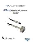
EZ-Ethernet Card
Card easily installs
inside the EZTouch
Panel
1–4
EZ-Ethernet Card Installation and User Manual
Chapter 1: Getting Started
2.
3.
1.
4.
5.
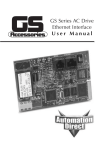
Typical EZ-Ethernet System
To begin designing and configuring your EZTouch panel with EZ-Ethernet card,
you will likely be using the following shown above:
1. EZTouch panel with EZ-Ethernet Card installed. Note: Panel must have “-F” in
part number and have firmware C.4 or higher. See EZTouch software manual
for firmware upgrade instructions.
2. Personal computer with the following installed:
• EZTouch panel software (version 2.2 or higher
• Ethernet network interface card (10BaseT or 10BaseFL)
• DirectSoft programming software
3. DL205 or DL405 PLC with H24-ECOM module installed. Note: H2/H4-ECOMs
must have firmware V1.0.197 or later to communicate with EZ -Ethernet, Ethernet
PLUS panels. To get future firmware updates, go to www.hosteng.com, under
Support. Instructions are available for upgrading firmware.
4. Standard ethernet workgroup hub and at least three CAT-5 ethernet patch
cables. (Hub shown is Automationdirect.com P/N: RT-CNFGKIT, and includes
4 CAT-5 patch cables and one CAT-5 crossover cable. All cables are 5 feet
long.)
5. 24VDC power supply for EZTouch panel. (Power supply shown is 50W, 2.0A
Automationdirect.com P/N: PS24-050D.)
1st Ed. Rev. D
1/04
EZ-Ethernet Installation and User Manual
1–5
Chapter 1: Getting Started
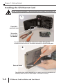
Installing the EZ-Ethernet Card
Warning: Disconnect input power to the EZTouch panel before installing the EZ-Ethernet Card.
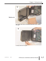
1.
Press tab to
open back cover
This section
of cover must
be removed
The bottom of the back plastic cover has a section that must be
removed to allow access to the cable connector on the EZTouch panel.
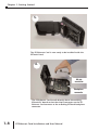
2.
Score cut marks
The plastic piece to be removed has cut marks, but use a screwdriver to
carefully score the cuts a little deeper so it breaks off easily.
1–6
EZ-Ethernet Card Installation and User Manual
Chapter 1: Getting Started
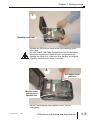
3.
Make two cuts
Use a sharp side cutter to carefully make the two cuts along
the edge.
4.
Carefully break off the piece.
1st Ed. Rev. D
1/04
EZ-Ethernet Installation and User Manual
1–7
Chapter 1: Getting Started
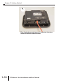
5.
The EZ-Ethernet Card is now ready to be installed inside the
EZTouch Panel.
6.
64-pin
connector
Backplane
connector
The EZ-Ethernet Card installs directly above the existing
EZtouch PC board so that the 64-pin connector on the EZEthernet Card connects to the matching EZTouch backplane
connector.
1–8
EZ-Ethernet Card Installation and User Manual
Chapter 1: Getting Started
7.
Mounting screw holes
Position the EZ-Ethernet Card so the two mounting screw
holes align.
DO NOT FORCE THE CARD CONNECTOR into the backplane.
Doing this may bend or break the pins and permanently
damage the Card. First, make sure that the pins are aligned
properly, and then press firmly into place.
8.
Self-tapping screw
goes here
Machine screw
goes here into
threaded hole
Secure Card using the two supplied screws. Do not
overtighten.
1st Ed. Rev. D
1/04
EZ-Ethernet Installation and User Manual
1–9
Chapter 1: Getting Started
9.
Close the back cover and press so it snaps back into place.
Connect the ethernet cable as shown.
1–10
EZ-Ethernet Card Installation and User Manual
SETTING UP &
USING THE
EZ-ETHERNET
CHAPTER
2
In This Chapter...
Setting Up Your EZ-Ethernet System . . . . . . . . . . .2–2
DIP Switch Settings . . . . . . . . . . . . . . . . . . . . . . . .2–2
Diagnostic LEDs . . . . . . . . . . . . . . . . . . . . . . . . . . .2–4
Tutorials . . . . . . . . . . . . . . . . . . . . . . . . . . . . . . . . .2–5
Tutorial A: First Time Connection . . . . . . . . . . . . . .2–5
Tutorial B: Adding PLCs to Your Project . . . . . . . .2–15
Tutorial C: Adding a Second EZTouch Panel . . . .2–20
EZ-Ethernet Firmware Upgrade Instructions . . . . .2–24
The EZ-Touch Panel Configuration Window . . . . .2–26
The NetEdit Window . . . . . . . . . . . . . . . . . . . . . .2–27
Chapter 2: Setting Up and Using the EZ-Ethernet Card
Setting Up Your EZ-Ethernet System
Use the system photo and information shown in Chapter 1 to help you connect
the EZ-Ethernet Card to your ethernet system. Make sure you have all the
hardware and software listed and that the revision levels match the requirements
given. Also refer to the manuals for the EZTouch panel, PLC, and ECOM module.
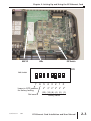
DIP Switch Settings
The EZ-Ethernet Card DIP Switch has eight slides. The factory default is for all
slides to be in the OFF position. Under normal use, you should not have to
change the settings. However, if you wish to assign a “hard” (Module ID) address
for the EZ-Ethernet Module ID, you may do this by setting slides 0-5 as shown.
The Module ID equals the sum of the binary values of the slide switches set in
the ON position. For example, if you set slide switches 1, 2 and 3 to the ON
position, the Module ID will be 14 (8 + 4 + 2 = 14). Actual DIP Switch settings
can be viewed using NetEdit.
2–2
EZ-Ethernet Card Installation and User Manual
Chapter 2: Setting Up and Using the EZ-Ethernet Card
MAC ID
DIP Switch
LEDs
ON
DIP Switch
7
Leave in OFF position,
for factory testing
Not used
1st Ed. Rev. D
1/04
6 5
25
4 3 2 1
0
24 23 22 21 20
(32) (16) (8) (4) (2) (1)
Binary value
EZ-Ethernet Card Installation and User Manual
2–3
Chapter 2: Setting Up and Using the EZ-Ethernet Card
Diagnostic LEDs
The EZ-Ethernet Card has four indicator LEDs which show the status of the
following
Status Indicator
Power is good to the Card (Green if good).
Link Good Indicator
The green LINK GOOD LED is steady on when the EZ-Ethernet Card is correctly
connected to an active device on the network and is receiving 5VDC operating
voltage. The LINK GOOD LED verifies that the proper cables are connected, and
the Card is functioning correctly.
Link Active Indicator
The red link active LED flashes to indicate that the Card sees data traveling on the
network. If any network device is sending or receiving data, the link active LED
will be illuminated. In idle mode (no network traffic) this LED is OFF. During
heavy communication loads this LED will be steady on.
Error Indicator
If the Card’s red ERROR indicator is flashing or steady on, a fatal error has
occurred. The error may be in the Card itself, or a network problem may be
causing this symptom. The ERROR indication can be caused by a faulty ground,
an electrical spike or other types of electrical disturbances. Cycle power to the
system to attempt to clear the error.
2–4
EZ-Ethernet Card Installation and User Manual
Chapter 2: Setting Up and Using the EZ-Ethernet Card
Tutorials
Go through the following tutorials to learn how to set up your project and add a
PLC and additional EZTouch panels to your project.
Do not perform control functions over the internet.
Tutorial A: First Time Connection
After connecting your EZTouch panel (with the EZ-Ethernet Card installed) and
your PLC (with ECOM module installed) to your hub, launch the EZTouch
software and set up the project similar to the image below.
DirectLogic Ethernet RevA
Select Edit
Program OFFLINE
Choose panel type
Type name of project
1st Ed. Rev. D
1/04
Choose Ethernet
protocol
After setting up the project
information window as
shown, click on this button
labeled “View/Edit PLC Com
Setup”
EZ-Ethernet Card Installation and User Manual
2–5
Chapter 2: Setting Up and Using the EZ-Ethernet Card
The “Edit EZ-Touch Panel Configuration” window is displayed.
Click the “Select Panel” button to locate your panel.
In this tutorial, we will use the default
Configuration Mode (Connected to Network),
in order to select connected panels and
nodes (ECOMs).
The panel information will appear as shown below. If your panel is not found, check the
LINK GOOD LED on the EZ-Ethernet Card and the LINK/ACTIVITY LED on the hub.
Note: The Module ID comes factory set as Ø.
MAC ID
Module ID
Click “OK”.
2–6
EZ-Ethernet Card Installation and User Manual
Chapter 2: Setting Up and Using the EZ-Ethernet Card
Notice that the panel information is now filled in on the “Edit EZ-Touch Panel
Configuration” window.
Note: The
Node Numbers
(1-10)
correspond to
the PLC
Station
Address in the
EZTouch
software. For
a full
description,
see the
EZTouch
software Help
file under
“DirectLogic
PLCs”.
Next, click on “Add Node” to locate and connect any ECOM modules you have
connected to your hub. Once a node is added, the panel will communicate to it.
Module ID
The ECOM information is shown like that of the panel. Click “OK” to
select the ECOM. The H2-ECOM and H4-ECOM modules also come
factory set with a Module ID of Ø. (This ECOM had been previously
set to 4, using NetEdit.)
1st Ed. Rev. D
1/04
EZ-Ethernet Card Installation and User Manual
2–7
Chapter 2: Setting Up and Using the EZ-Ethernet Card
Note: If connecting to more than one PLC, we strongly suggest
assigning your ECOMs’ Module IDs as 1 to 10, to correspond to its
number (# column) in the list. This number is used to designate the
Station Address the EZTouch panel uses to address the PLC. For
example, 2-V3000 is PLC 2’s V3000 register.
NOTE! NetEdit
must be used
to make any
modifications
to EZ-Ethernet
and ECOMs
(such as:
Module ID,
Module Name,
and IP
Address).
As suggested, to change an ECOM’s Module ID from 4 to1,
click on the “NetEdit” button.
Change the ECOM’s Module
ID to 1. Click ‘Update’ then
‘Exit’.
2–8
EZ-Ethernet Card Installation and User Manual
Chapter 2: Setting Up and Using the EZ-Ethernet Card
Now notice that the Module ID
does not show its new setting
Select the row of the node and
click ‘Add Koyo Node’, to reselect the ECOM.
Now the ECOM’s Module ID is
displayed accurately in the
Panel Configuration window.
Click Download to Panel to save
this configuration to the panel.
This panel is now connected to
one ECOM.
Now click ‘OK’.
Please remember, the actual Module ID is set by NetEdit. Any new
changes made by NetEdit will not be displayed in the Panel
Configuration window until re-selected, as shown here.
1st Ed. Rev. D
1/04
EZ-Ethernet Card Installation and User Manual
2–9
Chapter 2: Setting Up and Using the EZ-Ethernet Card
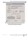
Finally, click “OK” on the “Project Information” window.
The EZTouch software will now open
your newly created project.
DirectLogic Ethernet RevA
2–10
EZ-Ethernet Card Installation and User Manual
Chapter 2: Setting Up and Using the EZ-Ethernet Card
Select the “Pushbutton” object to place a
pushbutton on the touch panel.
Give the push button a tag name of C1. We have also selected
a green On color and a red Off color. Click “OK”.
1st Ed. Rev. D
1/04
EZ-Ethernet Card Installation and User Manual
2–11
Chapter 2: Setting Up and Using the EZ-Ethernet Card
Assign this tag to PLC address C1 and click “OK”.
Next, place the object on the screen.
2–12
EZ-Ethernet Card Installation and User Manual
Chapter 2: Setting Up and Using the EZ-Ethernet Card
Click on the “Write to
Panel” button to
download your project
to the EZTouch panel.
Select Ethernet and
click “Start” to begin
writing the project.
1st Ed. Rev. D
1/04
EZ-Ethernet Card Installation and User Manual
2–13
Chapter 2: Setting Up and Using the EZ-Ethernet Card
Click “OK”. Now check your panel
to see if the push button you
added works properly.
To add PLCs to your project, go to Tutorial B. To add an additional
EZTouch panel, go to Tutorial C.
2–14
EZ-Ethernet Card Installation and User Manual
Chapter 2: Setting Up and Using the EZ-Ethernet Card
Tutorial B: Adding PLCs to Your Project
Beginning with the project “Ethernet10.ezt” created in the first
tutorial, click on “Setup”, then “Select PLC” to add a second PLC.
Click “View/Edit Attributes” to bring up the “Edit EZTouch Panel
Configuration” window.
1st Ed. Rev. D
1/04
EZ-Ethernet Card Installation and User Manual
2–15
Chapter 2: Setting Up and Using the EZ-Ethernet Card
Now, select the next row (Row 2), and click the “Add Koyo Node” button.
Select the new ECOM module listed, and click “OK”.
2–16
EZ-Ethernet Card Installation and User Manual
Chapter 2: Setting Up and Using the EZ-Ethernet Card
Select the new ECOM
module, and click
“NetEdit”. We will
now change the new
ECOM’s Module ID to
2, to match its Station
Address (#).
Select the Module ID, and enter “2”. Click “Update”.
NOTE! NetEdit
must be used
to make any
modifications
to EZ-Ethernet
and ECOMs
(such as:
Module ID,
Module Name,
and IP
Address).
1st Ed. Rev. D
1/04
EZ-Ethernet Card Installation and User Manual
2–17
Chapter 2: Setting Up and Using the EZ-Ethernet Card
Now notice that the Module ID
does not show its new setting
(2). Select the row of the node
and click ‘Add Koyo Node’, to
re-select the ECOM.
The ECOM’s Module ID is now
displayed accurately in the
Panel Configuration window.
Click Download to Panel to save
this configuration to the panel.
This panel is now connected to
two ECOMs.
2–18
EZ-Ethernet Card Installation and User Manual
Chapter 2: Setting Up and Using the EZ-Ethernet Card
You can now add another
pushbutton, this one mapped to
the 2nd PLC (ECOM).
Follow the same steps as in the first tutorial and
write the project to the panel.
1st Ed. Rev. D
1/04
EZ-Ethernet Card Installation and User Manual
2–19
Chapter 2: Setting Up and Using the EZ-Ethernet Card
Tutorial C: Adding a Second EZTouch Panel
This tutorial actually writes the existing project to an additional panel,
identical to the first EZTouch panel.
Physically connect your second EZTouch panel to the hub. Just as in
Tutorial A, click on “Write to Panel”.
2–20
EZ-Ethernet Card Installation and User Manual
Chapter 2: Setting Up and Using the EZ-Ethernet Card
Click “Select
Panel”
Click “Select
Panel”
1st Ed. Rev. D
1/04
EZ-Ethernet Card Installation and User Manual
2–21
Chapter 2: Setting Up and Using the EZ-Ethernet Card
Select the new panel
and click “OK”.
Notice that the new panel information is now listed. You can now download this
configuration to the panel. Click “OK”.
2–22
EZ-Ethernet Card Installation and User Manual
Chapter 2: Setting Up and Using the EZ-Ethernet Card
Click “Start” to write the EZTouch project (program) to the new panel, and click
“OK” to acknowledge. Now, both panels have the same ethernet configuration,
with any PLCs [ECOMs] configured, and the same project.
Repeat this procedure to add other EZTouch panels.
1st Ed. Rev. D
1/04
EZ-Ethernet Card Installation and User Manual
2–23
Chapter 2: Setting Up and Using the EZ-Ethernet Card
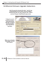
EZ-Ethernet Firmware Upgrade Instructions
Note! You must first download the latest *.ceb file from
the AutomationDirect.com website (Technical Support >
EZTouch panel page). Be sure to paste the new *.ceb file
into the C:\Program Files\EZTouch\Firmware folder.
To Upgrade a panel’s
EZ-Ethernet firmware,
select ‘Edit Program
OFF-LINE’ and choose
the correct project.
Click ‘View/Edit PLC
Com Setup’.
DirectLogic Ethernet RevA
Make sure you have the
correct panel, and click
‘Upg Firmware’.
2–24
EZ-Ethernet Card Installation and User Manual
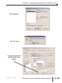
Chapter 2: Setting Up and Using the EZ-Ethernet Card
Click ‘Download’.
Click ‘OK’, twice.
You can now confirm the
new OS version using
NetEdit.
1st Ed. Rev. D
1/04
EZ-Ethernet Card Installation and User Manual
2–25
Chapter 2: Setting Up and Using the EZ-Ethernet Card
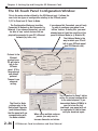
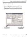
The EZ-Touch Panel Configuration Window
This is the main window utilized by the EZ-Ethernet card. It allows the
user to do two types of configuration relating to the EZTouch panel:
1) PC to Panel and 2) Panel to Node.
The Configuration Mode can be either
Connected to Network or Not Connected to
Network. If you choose Connected, you will
be able to ‘see’ actual devices that are
physically connected to your PC’s Ethernet
network (by hubs, etc).
If you choose Not Connected, you will only
be able to configure your panel in an
‘offline’ fashion. In doing this, you must
already know at least the specifics of the
panel’s Address Mode (e.g. Module ID).
The Address Mode is the
way in which your PC will
talk to your EZTouch panel
(and EZ-Ethernet card).
Protocol is the
Ethernet
protocol your
PC will use to
talk to the
EZTouch
panel. IPX is
the preferred
and default
protocol.
Timeout is an
advanced
setting.
The Panel to Node
settings refer to the
Retries and Timeouts
(and Address Mode)
that the panel will use
communicating with
the Node selected.
2–26
The ‘Download to Panel’ button
writes the current configuration
to the selected panel. If you
have added Nodes (ECOMs) to
your list since the last
download, your panel will not
be configured to talk to them
until you download again.
When using multiple nodes or
panels, you may need to
increase timeouts and retries.
EZ-Ethernet Card Installation and User Manual
Chapter 2: Setting Up and Using the EZ-Ethernet Card
The NetEdit Window
NetEdit is a utility which edits ECOM and EZ-Ethernet devices. It can be
used to change Module ID, Name, Description, Protocol, and IP
Addresses. It also allows the user to view the device’s current
Firmware Version, Booter Version and DIP Switch settings. Please see
your H24-ECOM-M manual for additional information on NetEdit.
Click on ‘Query Network’ to
re-scan the network for
newly added devices.
1st Ed. Rev. D
1/04
Click on ‘Update’ to make
any changes take effect on
the selected device.
EZ-Ethernet Card Installation and User Manual
2–27
SPECIFICATIONS &
ERROR CODES
APPENDIX
A
In This Appendix...
EZ-Ethernet Card Specifications . . . . . . . . . . . . . . .A–2
Ethernet Cable . . . . . . . . . . . . . . . . . . . . . . . . . . . .A–3
EZ-Ethernet Error Code Descriptions . . . . . . . . . . .A–3
Appendix A: Specifications and Error Codes
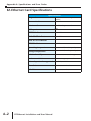
EZ-Ethernet Card Specifications
Specifications
Communications
LEDs/Network Monitoring Software
(NetEdit)
10BaseT
Data transfer
10 million bits per second
Cable port
RJ45
STATUS Indicator
Green LED
LINK GOOD Indicator
Green LED
LINK ACTIVE Indicator
Red LED
ERROR Indicator
Red LED
Operating temperature
32° to 140° F (limited to panel spec)
Storage temperature
-4° to 158° F (limited to panel spec)
Relative humidity
30% to 95% (non-condensing)
Environmental air
No corrosive gases permitted
Network protocols supported
Novell IPX, UDP/IP
Manufacturer
Host Automation Products
Link distance
100 meters (328 feet)
Diagnostics
A–2
EZ-Ethernet Installation and User Manual
Appendix A: Accessories
Ethernet Cable
A patch (straight-through) cable is used to connect a PLC (or PC) to a hub or
repeater. A crossover cable is used to connect the EZ-Ethernet Card to an ECOM
module, or a PC and a PLC or two hubs. We recommend that you purchase
cables pre-assembled with connectors for convenient and reliable networking.
EZ-Ethernet Error Code Descriptions
"Missed at least one frame"
The EZ-EThernet Card did not see one or more page mode requests from the
Panel. The user should re-attempt the previous operation. If the problem persists,
please contact Technical Support.
"Adapter could not lock Shared Ram"
The EZ-Ethernet Card was denied a request to lock one or more internal data
transfer buffers. This problem is considered critical and may require a panel reset
to restore proper operation. If the problem persists, please contact Technical
Support.
"Node ID ???? is not responding"
The Node with Module ID ???? is not responding to the EZ-Ethernet card. If seen
by the user, this message will immediately be replaced by the more generic "Plc ?
is Offline" (where ? is the Node ID as configured in the EZ-EThernet configuration
utility. The user should check both the physical and logical link between the Panel
and the PLC.
1st Ed. Rev. D
1/04
EZ-Ethernet Installation and User Manual
A–3
Appendix A: Specifications and Error Codes
"Invalid tag type"
Internal error that indicates the EZ-Ethernet Card was given a tag to process in
which the tag type is invalid. Operations on that tag only will be halted. This
might indicate a corrupt EZ-Touch Project tag database.
"Could not append pointer table"
The EZ-Ethernet card encountered a fatal internal error. The user should reset the
panel. If the problem persists, the user should contact Technical Support.
"Could not build transactions"
The EZ-Ethernet card encountered a fatal internal error. The user should reset the
panel. If the problem persists, the user should contact Technical Support.
"No nodes defined"
The panel is attempting to obtain information for a program in which the EZEthernet Card is not configured to process. This error would most likely be seen if
the user placed a factory EZ-Ethernet Card into a Panel that has an existing
program. The user should configure the EZ-Ethernet card to eliminate this
problem.
"No Items to process"
The EZ-Ethernet Card attempted either a read or a write tag operation when there
were no valid tags to process. User should retry the operation. If the problem
persists, the user should contact Technical Support.
"No gateway address"
Attempt was made to communicate with a node that is located behind a router,
but no gateway address was configured for the device. The user should add the
appropriate gateway IP address to the node in the EZ-Ethernet Card Configuration
Utility and download the new configuration to the panel.
"Tag references non-existing node"
An error condition in which the panel is requesting service for a tag that does not
have a corresponding node configured in the EZ-Ethernet internal node
configuration table. The user should either delete the tag or configure a node for
the tag.
"No valid address for node"
The EZ-Ethernet Card was not able to use the configured ECOM information to
contact an ECOM device. The user should re-check the EZ-Ethernet node
configuration.
A–4
EZ-Ethernet Installation and User Manual
Appendix A: Accessories
"Node ID is offline; Reason"
Not used in this release.
"Node ID
is offline; Reason unknown"
Not used in this release
"Node ID ???? : No more ecom buffers"
A condition in which EZ-Ethernet Card requests are being discarded by the node
indicated by ???? because the ECOM transaction buffers are saturated. The user
should reduce the load on the ECOM by optimizing panel screens and/or
removing panels configured to talk through that ECOM.
"Program Segment packet timeout"
An exchange between the EZ-Touch Program Loader and the corresponding EZEthernet Card was not completed in the time-out period specified in the EZEthernet Configuration Utility. The user should retry the operation. If this error
occurs frequently, the user should increase the time-out setting.
"Could not write point"
An EZ-EThernet adapter was unable to process a tag write request. The user
should retry the operation. If the problem persists, the user should contact
Technical Support.
"Tag scan off. Cannot complete Operation"
Not used in this release.
"Critical. No more transaction buffers"
The EZ-Ethernet Card has exceeded its resources attempting to handle the tags for
a given panel screen. The user should spread the tags across screens to prevent
this error.
"Packet send error"
Generic error that occurs if the EZ-Ethernet Adapter cannot send an Ethernet
packet. If the problem persists, the user should contact Technical Support.
"Read Transaction failed"
The EZ-Ethernet Card was unable to process an incoming tag data response from a
node. If the problem persists, the user should contact Technical Support.
1st Ed. Rev. D
1/04
EZ-Ethernet Installation and User Manual
A–5
Appendix A: Specifications and Error Codes
"Discrete Value must be 0 or 1"
The EZ-Ethernet was instructed to perform a discrete operation on a tag that had a
non-binary (0 or 1) value. This would happen only if the EZ-Touch tag database is
corrupt.
"Attempted operation on NULL pointer"
Internal EZ-Ethernet Card Error. If this error persists, the user should check his EZTouch Project and the EZ-Ethernet configuration.
"Could not build internal arrays"
Fatal internal EZ-Ethernet Adapter error. Please call Technical Support.
"Did not receive response from tag write"
The EZ-Ethernet Card sent one or more tag write requests that did not respond
within the timeout period. The user should resend the request. If the problem
persists, the user should increase the timeout period for the corresponding node
using the EZ-EThernet Configuration Utility.
"Adapter write Queue Overflow"
The EZ-Ethernet can normally process up to twenty-five multiple write requests
simultaneously. However, under some situations, the write queue could be over
run with requests. The user should ensure that the network has significant
bandwidth to handle the traffic.
"Adapter Read Queue Overflow"
Not used in this release.
"Direct Net send request failed"
The EZ-Ethernet Card was unable to send a Koyo DirectNet protocol packet.
Contact Technical Support.
"K-Sequence send request failed"
The EZ-Ethernet Card was unable to send a Koyo K-Sequence protocol packet.
Contact Technical Support.
"K-Sequence negative response"
The EZ-Ethernet Card received an error response from the targeted slave node.
A–6
EZ-Ethernet Installation and User Manual
Appendix A: Accessories
"Write tag retry count exceeded"
The EZ-Ethernet Card was unable to successfully process a user tag write request.
This occurs only after the attempt failed for the number of retries specified for the
node in the EZ-Ethernet Configuration Utility. This error normally indicates a
network problem. The user should adjust the node's timeout and retry settings
until this error is no longer seen.
"Exceeded system tag limit"
The EZ-Ethernet adapter was told to process a single screen of data that contained
more than the tag limit (500 tags/screen for reads, 25 tags/request on writes). The
user should spread some of the tags across a second screen.
"PLC not in TERM; Tag write inhibited"
The user attempted to write a tag when the target PLC's switch was not set to
"Terminal". The user should place the switch in Terminal mode so writes can be
processed. The inhibited write must be re-issued after the PLC is placed in
Terminal mode.
1st Ed. Rev. D
1/04
EZ-Ethernet Installation and User Manual
A–7
EZ-ETHERPLUS
APPENDIX
B
b
In This Appendix...
Introduction . . . . . . . . . . . . . . . . . . . . . . . . . . . . . .B–2
Configuring MODBUS/TCP Nodes . . . . . . . . . . . . .B–3
Things to Remember . . . . . . . . . . . . . . . . . . . . . . .B–9
Appendix B: EZ-ETHERPLUS
Introduction
The EZ-ETHERPLUS adapter is an enhancement of the EZ-Ethernet
communications controller family that, in addition to the Host Protocol, provides
MODBUS/TCP connectivity. Those familiar with the EZ-Ethernet configuration
and operation should find using Modbus to be straightforward. Those who are not
familiar with the package may wish to review the entire manual.
Note: You must have EZ-TOUCHEDIT Software version 3.1 or later, and EZ-TOUCH
firmware version D2 or later to use EZ-ETHERPLUS.
You also must have an EZ-ETHERPLUS card installed in any -F or -FS panel
(EZ-T10C-FS, for example).
The standard Modbus 1-based addressing scheme is supported, as shown in
Table 1 below.
Table 1 Supported Addresses
Input Discrete
Status
Input Register
Holding Register
Designator
Range
Minimum
Maximum
0
1
3
4
1-9999
1-9999
1-9999
1-9999
00001
10001
30001
40001
09999
19999
39999
49999
The following data types are supported:
Table 2 Data Types
Discrete
Unsigned INT
Signed INT
Unsigned Long INT
Signed Long INT
Floating Point
Char
1
Length (bytes)
Length (bits)
1
2
2
8
16
16
4
32
4
4
1
32
32
8
Range
40
1
The EZ-ETHERPLUS supports the Modicon/AEG standard for long integer and floating
point storage. That is, each of these 32-bit types is stored in two contiguous 16-bit locations,
starting with the specified address. For example, a LONG stored at 40032 uses both 40032
and 40033 to store the value. 32-bit register mode is not supported.
Before You Start
Before proceeding, you should know the following information about the
Modbus slave device you wish to monitor.
1. The name of the Modbus slave device. (Optional)
2. The Internet Protocol (IP) address of the Modbus slave device.
3. The Internet Protocol (IP) address of the network gateway if the panel is not on
the same network segment as the Modbus slave device.
Note: If you are using a general-purpose network, i.e., an intranet, as the
communication media, we recommend you consult first with your network
administrator before connecting any device to the network.
B–2
EZ-Ethernet Installation and User Manual
Appendix B: EZ-ETHERPLUS
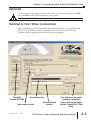
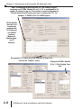
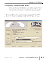
Configuring MODBUS/TCP Nodes
Modbus controllers are configured similarly to Koyo nodes by using the EZ-Touch
Panel Configuration utility shown below; however, unlike Koyo nodes, you must
manually enter the configuration for each Modbus node. This is done in “Offline”
mode. Please follow the steps below to configure the EZ-ETHERPLUS adapter.
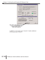
1. Choose your Project Name, select Panel Type, then select Modbus TCP/IP.
To enter the Configuration Utility, select “View/Edit PLC Com Setup.”
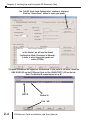
2. You must be in “Connected to Network” Configuration Mode to use the
1st Ed. Rev. D
1/04
EZ-Ethernet Installation and User Manual
B–3
Appendix B: EZ-ETHERPLUS
Select Panel feature. If the panel is not available online, you may complete
the configuration by selecting the “Not Connected to Network”
Configuration Mode and entering the appropriate data for each field in the
“PC to Panel Config” section.
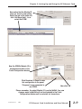
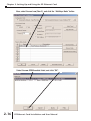
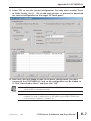
3. If this is a new panel configuration and the panel is online, press the ‘Select
Panel’ button to bring up a list of available panels. Select the one you wish
to configure and press OK.
B–4
EZ-Ethernet Installation and User Manual
Appendix B: EZ-ETHERPLUS
4. Select the “Not Connected to Network -- Modbus/TCP” Configuration Mode.
5. Select the row in the ‘Panel to Node Configuration’ section in which
you wish to insert the Modbus device.
1st Ed. Rev. D
1/04
EZ-Ethernet Installation and User Manual
B–5
Appendix B: EZ-ETHERPLUS
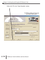
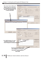
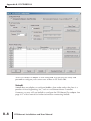
6. Select the ‘Add/Edit Panel to Node’button. This will bring up a new dialog
box.
502
7. Enter the name of the Modbus device, if one exists. The name is for
reference only. It is not used to connect the node to the panel.
8. Select the ‘Modbus/TCP’ protocol. This will disable all addressing mode
fields except IP and the Gateway. Also note that the Port field is changed to
the assigned Modbus/TCP port of 502.
Note: It is recommended to select either “Modbus/TCP” or “Host” for all nodes. Do not
mix the two protocols.
9. Enter the IP address of the Modbus device.
10. Enter the gateway address only if you are going through a gateway.
Otherwise, leave this field to the default of zeros.
502
B–6
EZ-Ethernet Installation and User Manual
Appendix B: EZ-ETHERPLUS
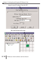
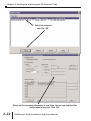
11. Select ‘OK’ to save the current configuration. You may select another ‘Panel
to Node Config’ slot (1 - 10) to add more devices, or proceed to download
the current configuration to the target EZ-Touch panel.
12. Now that you have added a node to the panel configuration, you must
connect to the EZ-ETHERPLUS Card, so the configuration can be loaded to
it. Click “Download to Panel” and then click “OK”.
Note 1: If the configuration is not downloaded, the EZ-ETHERPLUS card will not know
which nodes to communicate with.
Note 2: As more nodes are added, the addressing format will change slightly. For
example, if a node is added to line 5, the addressing for objects tied to that
node would be 5-400001, 5-300001, etc.
1st Ed. Rev. D
1/04
EZ-Ethernet Installation and User Manual
B–7
Appendix B: EZ-ETHERPLUS
Your EZ-ETHERPLUS adapter is now configured. You may exit this utility and
proceed to configure your custom user screens in EZ-Touch Edit.
Netedit
Netedit does not display or configure Modbus slave nodes unless the slave is a
product of Host Engineering, Inc., such as our Ethernet Motor Controller.
However, you may still use NetEdit to configure the EZ-Ethernet Plus adapter. See
page 2-27 of this manual for further information concerning NetEdit.
B–8
EZ-Ethernet Installation and User Manual
Appendix B: EZ-ETHERPLUS
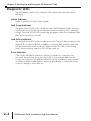
Things to Remember
TSince Modbus/TCP is a connection-oriented service, it is possible to have an
active connection without actually receiving data from the PLC. Such a condition
results in the panel displaying “Read tags retries exceeded”. However, if the actual
TCP connection is broken, then the message “PLC’s xx is offline” displays (where
xx is a number 1 to 10).
The EZ-ETHERPLUS is designed to communicate with all slave devices through
the standard assigned MODBUS/TCP port 502. This parameter is not configurable.
The EZ-ETHERPLUS may be used only on a one node per IP address basis. That is,
changing the Modbus Slave ID will not affect the communications.
The EZ-ETHERPLUS is designed to ignore this setting and to use the IP address of
the slave to distinguish devices on a given network.
IMPORTANT: Never assign duplicate IP addresses. Doing so could result in erratic
behavior by the EZ-ETHERPLUS device.
When configuring Modbus slaves, keep in mind that the adapter operates more
efficiently when the nodes are configured in contiguous slots, starting with slot
number one.
1st Ed. Rev. D
1/04
EZ-Ethernet Installation and User Manual
B–9