1
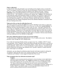
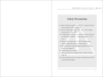
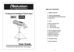
Owner‘s Manual
FOLLOW SPOT
1200 PRO
Congratulations on your purchase of this Follower Spot Light.
To get the most from your equipment you must read all of this manual
before using it first time.
Table of Contents
1. Safety Instruction........................................................................... 3
2. Technical Specification.................................................................... 4
3. Lamp.............................................................................................. 5
4. How to setup the Unit.................................................................. 7
4.1 Control Panel.......................................................................... 7
4.2 Main Function........................................................................ 7
4.3 Home Position Adjustment..................................................... 9
5. How to control the Unit.............................................................. 10
5.1 DMX Controller..................................................................... 10
5.2 Dedicated Controller............................................................. 11
5.3 DMX512 Configuration......................................................... 12
5.4 DMX512 Connection............................................................ 13
6. Troubleshooting........................................................................... 14
7. Fixture Cleaning........................................................................... 14
8. Disposal....................................................................................... 15
9. Technical Specifications................................................................ 15
2
1. Safety Instruction
You have to carefully read the instruction, which includes
important information about the installation, usage and
maintenance.
• Please keep this User Guide for future consultation. If you sell the unit
to another user, be sure that he also receives this instruction booklet.
• Unpack and check carefully there is no transportation damage before
using the unit.
• Before operating, ensure that the voltage and frequency of power supply
match the power requirements of the unit as stated in this manual.
• It’s important to ground the yellow/green conductor to earth in order to
avoid electric shock.
• The unit is for indoor use only. Use it only in a dry location. Exposing the
device to rain or moisture would cause the risk of electrical shock or fire.
• The unit must be installed in a location with adequate ventilation, at least
50 cm from adjacent surfaces. Be sure that no ventilation slots are blocked.
• Disconnect the device from the mains power before any servicing or
maintenance.
• Replace fuse/lamp only with the same type. Do not use any other type
of lamp.
• Keep any flammable material away from the unit while it is operating.
Otherwise you run the risk of causing a fire.
• Use safety cables when fixing this unit. Don’t handle the unit by taking
its head only, but always by taking its base.
• Maximum ambient temperature is TA: 40°C. Don’t operate it where the
temperature is higher than this.
• Unit surface temperature may reach up to 85°C. Don’t touch the
housing barehanded during its operation. Turn off the power and allow
about 15 minutes for the unit to cool down before replacing bulb or
servicing as the unit could be very hot. Also don’t touch the bulb with
bare fingers, as it is very hot after using.
• Hot lamp explosion hazard! Do not open the unit within five minutes
after switching off.
• Do not start the unit without bulb enclosure or if the housing is damaged.
• The housing, the lenses, or the ultraviolet filter must be replaced if they
are visibly damaged.
• In the event of serious operating problem, stop using the unit
immediately. Never try to repair the unit by yourself. Repairs carried out
3
•
•
•
•
by unskilled people can lead to damage or malfunction. Please contact
the nearest authorized technical assistance centre. Always use the
same type spare parts.
Do not connect the device to any dimmer pack.
Do not look directly at the light while the unit is on.
There are no user serviceable parts inside the unit. Do not open the
housing or attempt any repairs by yourself. If the fixture shows any
visible damage or if your unit may require service, please contact your
nearest dealer.
The unit must be mounted via its mounting system (as show below).
Always ensure that the unit is firmly fixed to avoid vibration and slipping
while operating. Always ensure that the structure to which you are
attaching the unit is secure and is able to support a weight of 80 kg for
each unit.
2. Technical Specification
Power supply
• AC 230V 50Hz
Lamp
• MSI 1200W/S / HMI 1200/S K SFc15.5-6
Optical system
• High efficiency optical system
• High quality optical lens and dichroic colours
• Beam angle: 13°
Shutter/Dimmer
• Blackout, 0~100% smooth dimming and strobe speed variable (1~12
flashes per second)
Movement
• Pan: 360° Tilt: 90°
Colour Wheel
• 8 dichroic colours plus white colour
• Rainbow effect at variable speeds
Colour Temperature
• Standard 6000K, adjustable 5600K and 3200K
4
DMX Channels
• Standard DMX512 signal addressing and controlled by any universal
DMX controller
Channel 1 = Shutter
Channel 2 = Iris
Channel 3 = Colour
Channel 4 = Colour temperature
Channel 5 = Dimmer
Channel 6 = Focus
Luminous intensity:
3. Lamp
In case of replacement of the lamp or maintenance, do not open
the fixture within 15 minutes until the unit cools down after
switching off.
Because of its high internal pressure, there might be a risk that the
discharge lamp would explode during operation. The lamp emits intense UV
radiation which is harmful to the eyes and skin. The high luminance of the
arc can cause severe damage to the retina if one looks directly at the lamp.
MSI 1200W/S / HMI 1200/S K SFc15.5-6
1. Always switch off the main supply and never handle the lamp or
luminant when it is hot.
2. Do not touch the bulb with bare hands. If this happens, clean the lamp
with denatured alcohol and wipe it with a lint free cloth before installation.
3. The lamp generates UV radiation. Never operate the lamp without
appropriate shielding.
4. When burning, the lamp operates at high pressure and there is a slight
risk of arc tube rupture. The risk increases with age, temperature and
improper handling of the lamp. Do not use the lamp any longer than its
specified life.
5. Make sure the lamp is located in the centre of the reflector for the best
spot.
5
Unscrew the thumb screw
6. If changing the lamp, remove old lamp from lamp socket. Hold the new
lamp only by its ceramic base. Never touch the glass bulb. Insert the
new lamp in the lamp socket.
7. With the nipple of the lamp facing the back insert one end of the lamp
into the socket. Pull up the spring of the other side of the socket and
snap the other end of the lamp into place. Make sure it fits correctly
into the socket. Please refer to the diagram to know how to put the
lamp in correct position.
6
4. How to setup the Unit
4.1 Control Panel
Display
To show the various menu and to select functions
Button
MENU
DOWN
UP
ENTER
To select the programming functions
To go backward in the selected functions
To go forward in the selected functions
To confirm the selected functions
On/Off
Turns On/Off the power
Fuse
To replace the fuse
Power
To connect the power plug
DMX input/output
For DMX 512 link, use 5-pin XLR plug cable to link the unit together.
4.2 Main Function
To select any of the given functions, press the MENU button up to when
the required one is showing on the display. Select the function by ENTER
button and the display will blink. Use DOWN and UP button to change
the mode. Once the required mode has been selected, press the ENTER
7
button to setup or it will automatically return to the main functions without
any change after idling 8 seconds. To go back to the functions without any
change press the MENU button. The main functions are showing below:
DMX 512 Address Setting
Press the MENU button until the
is showing on the display. Press
the ENTER button and the display will blink. Use DOWN / UP buttons to
change the DMX512 address. Once the address has been selected, press
the ENTER button to setup or automatically return to the main function
without any change after 8 seconds. To go back to the functions without
any change press the MENU button again.
Self test
Press the MENU button until the
is blinking on the display. Press
the ENTER button and the unit will run the built-in program for self-testing.
To go back to the functions press the MENU button.
Fixture Hours
Press the MENU button up to when the
is blinking on the display.
Pressing ENTER button and the display will show the number of working
hours of the unit. To go back to the functions press the MENU button
again.
Lamp ON/OFF
Press the MENU button until the
is blinking on the display. Press
the ENTER button and the display will blink. Use DOWN and UP button to
select the
(Lamp on) or
(Lamp off) mode. Once the mode
8
has been selected, press the ENTER button to setup or automatically
return to the main functions without any change after 8 seconds. To go
back to the functions without any change press the MENU button again.
Reset
Press the MENU button until the
is blinking on the display.
Pressing ENTER button and all channels of the unit will return to their
standard position. To go back to the functions press the MENU button
again.
4.3 Home Position Adjustment
Press MENU button for at least 5 seconds into offset mode to adjust the
home position, when you want to adjust gobo and colour home position,
you should be run
mode first, the functions are shown below:
Colour offset
Press the MENU button for at least 5 seconds into offset mode, use
DOWN and UP button up to when the
is shown on the display.
Press the ENTER button and the display will blink. Use DOWN and UP
buttons to adjust the colour home position. Once the colour has been
selected, press the ENTER button to setup or automatically return to the
offset functions after 8 seconds without any change. Press the MENU
button again to go back to the main functions without any change.
Effect offset
Press the MENU button for at least 5 seconds into offset mode, use
DOWN and UP button up to when the
is shown on the display.
Pressing ENTER button and the display will blink. Use DOWN and UP
button to adjust the effect home position. Once the effect has been
selected, press the ENTER button to setup or automatically return to the
offset functions after 8 seconds without any change. Press the MENU
button again, to go back to the main functions without any change.
9
Dimmer offset
Press the MENU button for at least 5 seconds into offset mode, use
DOWN and UP button up to when the
is shown on the display.
Pressing ENTER button and the display will blink. Use DOWN and UP
button to adjust the dimmer home position. Once the effect has been
selected, press the ENTER button to setup or automatically return to the
offset functions after 8 seconds without any change. Press the MENU
button again, to go back to the main functions without any change.
5. How to control the Unit
Two ways to operate:
1. By universal DMX controller
2. By dedicated controller
There’s no need to turn the unit off when you change the DMX address, as
the new DMX address setting will be effective at once. Every time you turn
the unit on, it will show “1200” on the display and move all the motors to
their ‘home’ position and you may hear some noises for about 20 seconds.
After that the unit will be ready to receive the DMX signal.
5.1 DMX Controller
If you use an universal DMX controller to control the units, you have to
set DMX address from 1 to 512 channels so that the units can receive the
DMX signal.
Press the MENU button up to when the
is shown on the display.
Press the ENTER button and the display will blink. Use DOWN and UP
button to change the DMX512 address. Once the address has been
selected, press and keep the ENTER button pressed up to when the
display stops blinking or storing automatically 8 seconds later. To go back
to the functions without any change press the MENU button again.
Please refer to the following diagram to address your DMX512 channel for
the first 4 units.
6 Channels:
10
5.2 Dedicated Controller
6 channels for international protocol DMX512. It can finish all operations
via dedicated controller without using other controllers. When the power
is switched on, the projector automatically starts to run the self-test. After
finishing these, the fixture is ready for operation.
1. DIMMER OPEN buttons: Holding the buttons, the light beam will
become stronger and stronger, then shutter will obtain max. value.
After releasing the button, the light beam and shutter resumes its initial
condition. There are 2 buttons on the both sides of the controller for
your convenient operation.
2. IRIS OPEN buttons: Holding the buttons, the light iris will become
bigger and bigger. After releasing the button it, the light beam resumes
its initial condition. There are 2 buttons on the both sides of the
controller for your convenient operation.
3. FIXED COLOURS & RAINBOW switch: Turning the switch on the
RAINBOW position, enable the rainbow function, you can set different
rainbow speed by pressing COLOUR buttons from slow to fast.
Turning the switch on the FIXED COLOURS position, enable the fixed
colours function and disable the rainbow function. They will save last
setting automatically in each step.
4. COLOUR buttons: There are 9 colour buttons of white, red, yellow,
magenta, green, orange, blue, pink and purple. Select the light beam
colours by pressing the relative colour buttons.
5. COLOUR TEMPERATURE switch: Adjusting this switch to obtain 3
kinds of colour temperature: Standard 6000K, 5600K and 3200K.
6. DIMMER slider: Adjusting the slider from 0% to 100% position, the
light beam will become more stronger and stronger till the dimmer
reach 100%.
11
7. SHUTTER slider: Adjusting the slider from slow to fast position, the
strobe speed will become from slow to fast.
8. IRIS slider: Adjusting the slider from min. to max. position, the light
beam size will become more bigger and bigger till the iris opened fully.
9. FOCUS slider: Adjusting the suitable focus by pushing this slider from
left to right.
5.3 DMX512 Configuration
12
5.4 DMX512 Connection
The DMX 512 is widely used in intelligent lighting control, offering a
maximum of 512 channels.
1. If you’re using a controller with 5 pins DMX output, you need to use a
5 to 3 pin adapter-cable.
2. At last unit, the DMX cable has to be terminated with a terminator.
Solder a 120 ohm 1/4W resistor between pin 2(DMX-) and pin
3(DMX+) into a 3-pin XLR-plug and plug it in the DMX-output of the
last unit.
3. Connect the unit together in a ‘daisy chain’ by XLR plug from the
output of the unit to the input of the next unit. The cable can not
branched or split to a ‘Y’ cable. DMX512 is a very high-speed
signal. Inadequate or damaged cables, soldered joints or corroded
connectors can easily distort the signal and shut down the system.
4. The DMX signal is able to pass through each fixture continuously, so
if one fixture in the chain is out of order, all the fixtures after this point
will not be affected.
5. Each lighting unit needs to have an address set to receive the data
sent by the controller. The address number is between 0-511 (usually
0 & 1 are equal to 1).
6. 3 pin XLR connectors are more popular than 5 pins XLR.
3 pin XLR: Pin 1: GND, Pin 2: Negative signal (-), Pin 3: Positive signal (+)
5 pin XLR:Pin 1: GND, Pin 2: Negative signal (-), Pin 3: Positive signal (+).
13
6. Troubleshooting
Following are a few common problems that may occur during operation.
Here are some suggestions for easy troubleshooting:
A. The unit does not work, no light and the fan does not work
1. Check the mains power supply and mains fuse.
2. Let a technician check the mains outlet for proper functioning.
B. Not responding to DMX controller
1. Check the address settings and DMX polarity.
2. If you have intermittent DMX signal problems, let a technician check
the pins on connectors or on PCB of the unit or the previous one.
3. Try to use another DMX controller.
4. Check if the DMX cables run near or run alongside to high voltage
cables that may cause damage or interference to DMX interface
circuit.
C. One of the channels is not working well
1. The stepper motor might be damaged or the cable connected to the
PCB is broken. Consult your dealer then.
2. The motor’s drive IC on the PCB might be out of condition. Consult
your dealer then.
D. The lamp is cutting out intermittently
1. The lamp is not working well. Let a technician check for proper mains
voltage.
2. Internal temperature may be too high. Check and if necessary replace
the fan.
7. Fixture Cleaning
The cleaning of internal and external optical lenses and/or mirrors must
be carried out periodically to optimise light output. Cleaning frequency
depends on the environment in which the fixture operates: damp, smoky
or particularly dirty surroundings can cause higher accumulation of dirt on
the unit’s optics.
• Clean with soft cloth using normal glass cleaning fluid.
• Always dry the parts carefully.
• Clean the external optics at least every 20 days. Clean the internal
optics at least every 30/60 days.
14
8. Disposal
Do not dispose of the device at the end of his operating life
in your normal domestic waste. This device is subject to the
European Guidelines 2002/96/EC.
• Have the product disposed of by a professional disposal company of by
your communal disposal facility.
• Observe the currently applicable regulations. In case of doubt contact
your disposal facility.
• Dispose of packaging materials in an environmentally
responsible manner.
9. Technical Specifications
Power Fuse
Lamp
Dimension
Weight
AC 230V~50HZ
6 x 30 mm Glass T15A
MSI 1200W/S / HMI 1200/S K SFc15.5-6
1170 x 330 x 225 mm
42.4 kg
15
2010
Musikhaus Thomann
Treppendorf 30 • 96138 Burgebrach
Germany • www.thomann.de