1
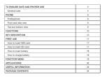
Production
of light effect
Oravicka street, P.O.Box 22
028 01 Trstena
Slovakia
++421 43/5392 877,5393 234
Shop : 043/5392 349
URL : http://www.trix.sk
E-mail : [email protected]
V
-10
0
rol
t
n
l
o
g c ontro
o
l
Ana 512 C
DMX
Carat RotoScan
D575, D250
H250
Your distributor :
USER
Manual
USER MANUAL
Before you initial start up this lighting, please read the following
instructions carefully!
Important: Damages caused by the disregard of this user manual are not
subject to warranty. We will not accept liability for any resulting defects or
problems. Therefore, it is absolutely necessary for you to follow the
safety instructions and warning notes written in this manual.This lighting
is only for power supply 230V/50Hz.For safety reasons, unauthorized
modifications are forbidden! Not only damages to the lighting can be the
result of unauthorized use but also you may endanger your own and the
safety of others.The electric connection must be carried out by qualified
person. This devise is an effect lighting and was not designed for
permanent use. When you install the lighting, make sure that there is no
highly flammable material within a distance of 1m (such as decoration
articles, curtains, wooden ceiling etc.).
Please keep away from children - lamp generates high temperature.
Lamps are not subject to warranty.
Ventilation
It is necessary to ensure cooling fans against their covering and secure
the device to have admission of air. If temperature reaches 77grd,
thermal fuse placed in device will disconnect of the mains.
Never use device without thermal fuse!!!
Location
Don't install the device at places with mechanical shakings and
vibrations, high dustiness or high temperature. Not keeping these
conditions can lead to shorter lifetime or its damage.
DON´ T expose the device to influence of water, rain or moisture. It
could lead to electric shock or fire.
Supply voltage
Don´t use any other supply voltage meant in technical specification and
manufacture label. Not keeping proper supply voltage could lead to
damaging the device,starting a fire or its wrong function.
Power cord
Check if power cord is not mechanical damaged and if it is connected
properly. Check also if the socket is designed sufficiently for needed
loading. Otherwise there is a danger of electric shock or a fire. Power
cord must not be bent excessively, led across sharp edges or given to
mechanical stress. Don´t pull the supply lead out by the flex but only by
the plug. The device must always be connected behind the main switch.
Do not touch the supply lead with wet hands, you are threatened by
electric shock.
Other important cautions
Don´t poke any objects into cooling fans and ventilator, it could lead to
a serious electric shock or damaging the device. Be careful of no water
or otherliquid entering.
cigarette smoke is being built up on the body of the device, but mainly on optical
system objective. Dust penetrates through the ventilator inside of the device
and settles on internal optical system consequently the light output is reduced
radically.Because there is a bigger danger of failure it is necessary to maintain
regularly. Follow these rules for cleaning: Objective requires cleaning by softcloth moistened in weak soapy solution. Internal parts, like optical system gobo,
dichroic filters clean monthly the same way, with soft smooth cloth moistened in
weak soapy solution. The gobos clean by soft brush. The interior of the projector
should be cleaned monthly. Ventilator and cooling fans should be cleaned
monthly by soft brush and vacuum cleaner. Adapt cleaning interval to density of
operating time.Never use for cleaning any solvents and similar chemicals,
grinding sponge for dishwashing, washing powder or cleaning agents with
grinding effect.
Service
Never try to repair, dismantle or do some construction changes in case of any
failure. Always consult qualified employee or dealer. Always replace the lamp
by consistent with used type or its equivalent
Technical specification
CaratRotoScan D250 H250
D575
Supply voltage
230V/50Hz
230V/50Hz 230V/250W
Power consumption
380W
320W
650W
Fuse
T3,15A
T3,15A
T6.3A
Light source
HSD250
24V/250W
HMI575
Socket cap
G9,5
G(Y) 6,35
SFc10
Lamp life
2000h
50-300 h
700-1000 h
Chromatic temperature 6000 K
3000 K
5600 K
Weight
15 kg
16 kg
24 kg
Dimensions /mm/
370x250x590
370x250x590 370x250x720
Optical system:
Parabolic mirror + 2x aspheric condensor
Double objective with balancing corecting error
Gobos, colours, effects ...
3 rotary gobos, 2 static gobos + circle, 7 dichroic colours + white, light bar for
blackout position, fluent adjustable dimmer, strobo effect with frequency 1-10
flash per second, Rainbow effect
Motors:
6 stepping motors controlled by microprocessors
Electronics:
Functions of the device controlled by microprocessor
Input and output controlling signal in protocol DMX 512
6 DMX channels
roll with coloured filters will start rotating. That is socalled “Rainbow effect“.
Speed is changing in dependence of value size and in 255 value rotary speed is
the biggest.
0
white
16
blue
32
red
48
green
64
orange
80
turquoise
96
yellow
112
pink
127
white
128-255
“rainbow effect“
Channel no. 4 Exchange gobo pictures. All the pictures can be changed..
0 - 21
circle
22 - 42
roto gobo
43 - 63
static gobo
64 - 84
roto gobo
85 - 105
static gobo
106 - 127
roto gobo
125 - 255
rainbow effect
From the value 128-255 the mentioned pictures
are changing linearly. Exchange speed is rising
by increasing its value.
Channel no. 5 Rotation
0 - 11
Stop no rotation
11 - 128
Rotation anticlockwise with falling speed ( value 128 stands
for maximum speed)
129 - 139
Stop no rotation
140 - 255
Rotation clockwise with increasing speed (value 255 stands
for maximum speed)
Channel no. 6 Strobo, Dimmer, Open
0
Screen closed
1 - 96
Linear Dimmer (gradual opening)
97 - 98
Screen open
99 - 100
Screen closed
101 - 125
Automatic Dimmer (gradual brightening)
126 - 150
Automatic Dimmer (gradual darkening)
151 - 240
Stroboscopic effect adjustable 1-10 flash per second
241 - 245
Screen open
246 - 248
Reset (246 247, 248 247)
249 - 255
Screen open
Maintenance
Disconnect the device from the mains before any maintenance work! To
secure no failure operation and long lifetime it is essential to clean the
device regularly. Dust with smoke from fog machines, air moisture and
Maintenance and cleaning
Don´t use any solvent and similar chemicals which could damage a surface
finish or some parts of the device. Use a soft and smooth cloth for cleaning
optical parts of device and its surface. Never use washing powders or other
cleaning agents with grinding effect.Connect the device to power supply
after complete drying.
Service
Never try to repair, dismantle or do some construction changes in case of
any failure. Always consult qualified employee or dealer. Not keeping this
rule you can suffer dangerous electric shock. Disconnect the device from
mains before replacing the lamp or dismantling the housing. Not keeping
this procedure you can suffer dangerous electricshock. Always replace the
lamp by consistent with used type or its equivalent. Unplug mains lead
before opening the housing and cleaning internal parts of device./optical
system, dichroic filters, etc./ You can suffer dangerous damage of sight by
discharge light.
Description of the device
5
6
4
3
1
2
11
1 -detent holder
2 - clawing holder
3 - upper cover
4 - objective
5 - mirror
6 - detent objective
7 - DMX output XLR connector
8 - DMX input XLR connector
9 - DIP switch
10 - LED indication of condition
11 - feet of the device
12 - fuse
13 - power cord
8
7
9
12
13
10
Unpacking
Unpack the device and after acclimatisation take off the protective foil.Make
sure that there are no damages caused by transportation.
Installation
The device can be installed in any position without altering its operation. For
mounting use bracket of device, which is a mounting hole in. First make
sure that the structure you are going to attach the projector is secure.
When installing the projector over the ground use the safe chain and steelwire rope as a double protection against falling down. Make sure the
housing is closed firmly with the screw tightened up. It is necessary to
ensure cooling fans against their covering / curtains etc./ and
secure ventilator and cooling fans to have admission of air.Before
opening the housing always disconnect the device from mains / power
cord must be unplugged from the socket/. Otherwise you can be set to
dangerous electric shock.The device is supplied from manufacturer
without light power. These are types of light power recommended by
manufacturer.
Procedure
1-Loose fastening screw
2-Pull out the upper cover
3-If you replace the lamp, first take out original one you used before
4-Insert new lamp into the socket. Never touch the glass-bulb
discharge lamp barehanded,always use bulb cover or dry cotton cloth
or gloves.
5-Make sure that the lamp is installed tightly.
6-Close the cover and tighten fastening screw.
Never use the light source with opened housing! You can suffer a serious
damage of sight By discharge light.
Connection to the mains
The device must always be connected behind the main switch .
Never connect the device through darkening device (dimmerpack)
Connection to the control signal - interconnection of devices
Each function of the device is addressed according to standard protocol
DMX 512 /1990/4 us. It means, we can control this device by any other
device, which provides signal included in protocol DMX 512 by serial
line. Connection is secured by screened double-line ended by
connector XLR with impedance 120ohm.
Functions of the device
Functions of the device are controlled by 8 DMX consecutive channels.
Addressing as well as functions of the device are selected on DIP switch
on its upper part.
DIP switch no.
function
1
PAN change of course X
2
TILT change of course Y
3 - 10 DMX address
1 2 3 4 5 6 7 8 9 10
DIP
Addressing of the device
Control signal DMX can remove data for 512 channels. The device works
with 6 DMX channels. DIP switch determines basic DMX address. It
means in practice you can controll the device with any other DMX
controller which works with 6 channels at least. There is indicated
adjusting DIP switch for various controllers, e.g. 6, 8, 12 channels, in the
following schedules. Channel choice is made by adjusting basic absolute
address on DIP switch according to the following schedules:
Schedule for adjusting DIP Switch 12 - channel controler version
Occupied channels 8
41 - 48 kanál
Switch value:
3
4
5
6
7
8
9
10
1
2
4
8
16 32 64 128 : 32+8=40
6
Schedule for adjusting DIP switch 8 - channel controler version
Schedele for adjusting DIP 6 - channel controller version
Occupied channels 6
1 - 6 channel
1
3
4
5
6
7
8
9
10
Occupied channels
8
1 - 8 channel
1
7 - 12 channel
2
9 - 16 channel
2
13 - 18 channel
3
17 - 24 channel
3
19 - 24 channel
4
25 - 32 channel
4
25 - 30 channel
5
33 - 40 channel
5
31 - 36 channel
6
41 - 48 channel
6
37 - 42 channel
7
49 - 56 channel
7
43 - 48 channel
8
57 - 64 channel
8
Schedule for adjusting DIP switch 12 - channel controller version
Occupie d cha nne ls 12
1 - 12 channel
1
13 - 24 channel
2
25 - 36 channel
3
37 - 48 channel
4
49 - 60 channel
5
61 - 72 channel
6
73 - 84 channel
7
85 - 96 channel
8
3
4
5
6
7
8
9
10
3
4
5
6
7
8
9
10
The device is addressed by basic
address which receives 6 DMX
channels from.It means in if you use e.
g. controller and want the device work
in sequence no. 6 (scanner no. 6), you
adjust the device to the address 40 (4148 6 (scanner sequence) x 8 (number
of channels the controller) 8 (number
of controller)channels on the controller)
Description of single controlling functions
Channel no. 1
Movement the mirror horizontally (X)
Channel no. 2
Movement the mirror vertically (Y)
Channel no. 3
Exchange colours
Channel no. 4
Exchange gobo pictures
Channel no. 5
Rotation
Channel no. 6
Strobo, Dimmer, Open
Channel no. 1 Movement the mirror horizontally /X/ - PAN
Range of values 0-255 determines position of the miror horizontally.
Values 0 and 255 adjust the mirror into one of excessive positions,
value 128 adjusts optical mid. By switching DIP switch no.
1 /PAN/ to the opposite position, excessive positions will
exchange / if 0 has been right, it will be left/.
Channel no. 2 Movement the mirror vertically /Y/ - TILT
Range of values 0-255 determine s position of the mirror vertically.
Values 0 and 255 adjust the mirror into one of excessive positions,
value 128 adjusts optical mid. By switching DIP no. 2 /TILT/ to the
opposite position, excessive positions will exchange /if 0 has been up,
it will be down/.
Channel no. 3 Exchanging colours
Linear exchange dichroic filters is made in values range 0-127, from the value 128 the