1
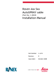
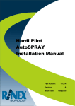
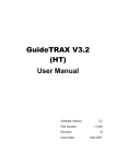
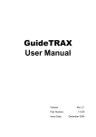
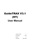
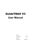
Raven 4x00
AutoSPRAY Cable
(Part No. 1-2811)
Installation Manual
Part Number:
1-1264
Revision:
B
Issue Date:
October 2008
INTRODUCTION
The Raven 4x00 AutoSPRAY Cable (Part No 1-2811) is designed to suit the
following installations:
Compatible Controllers
Raven 4400
Raven 4600
The cable will control up to six individual boom sections; where the controller is
configured with a Master Switch sense line it will be detected. See APPENDIX B
for detecting an external Master Switch.
Figure 1: AutoSPRAY Interface Cable (Part No 1-2811)
INSTALLATION
A schematic of the cable installation is shown in Figure 2.
Figure 2: Schematic layout of typical AutoSPRAY installation
1-1264 Rev B
Raven 4x00 AutoSPRAY Cable Installation
Page 1
It is recommended that all electrical wiring should be installed by
a qualified auto-electrician. Incorrect wiring may damage the
AutoSPRAY controller and/ or the spray rate controller.
The installation and configuration of the RINEX AutoSPRAY controller is detailed
in the appropriate User Manual.
Step
Instruction
1.
Check that the spray controller and boom section switches are
functioning correctly before commencing the installation.
2.
Locate the harness cable connected to the back of the Raven controller
and disconnect it.
3.
Plug the supplied 1-2811Raven 4x00 AutoSPRAY tee cable in-line
between the two mating connectors from Step 2.
4.
Confirm that the spray controller and boom section switches function
correctly before connecting the cable to the RINEX AutoSPRAY
controller.
Check that all section switches function correctly and the controller still
displays the correct flow rate.
5.
Connect the circular AMP connector on the supplied 1-2811 Raven 4x00
AutoSPRAY tee cable to the RINEX AutoSPRAY controller as detailed in
the AutoSPRAY installation manual.
The AMP connectors are keyed so that they will only fit one way and are
twisted clockwise to lock the connector in position.
6.
Confirm that the spray controller and boom section switches function
correctly.
Consult the AutoSPRAY controller installation manual to setup and
calibrate the AutoSPRAY system.
Note: If the RINEX AutoSPRAY controller is not connected directly to a 12Vdc
source (vehicle power), then it is necessary to connect the AutoSPRAY
cable to the vehicle power supply for correct operation of the system.
Refer to APPENDIX A for connecting to vehicle power.
1-1264 Rev B
Raven 4x00 AutoSPRAY Cable Installation
Page 2
APPENDIX A
CONNECTING POWER
Power for the AutoSPRAY Controller /cable must be a clean 12Vdc
source. Connecting the AutoSPRAY controller to 24Vdc will cause
damage to the controller. If connecting to a 24Vdc vehicle, 12Vdc
power must be connected to the same power source the spray
rate controller is using.
Step
1.
Instruction
Connect the RED wire, labelled POWER to a 12Vdc power source that is
controlled with the vehicle ignition wiring (power with the vehicle is
ON). Then connect the BLACK wire, labelled GROUND to a ground point
on the vehicle.
APPENDIX B
CONNECTING EXTERNAL MASTER
If the spray rate controller does not output a 12Vdc signal from the Master
Switch, an external Master Switch can be detected. The Master Switch detect
cable is embedded within the wiring loom near the AutoSPRAY controller
connector as shown in
Approximate location of embedded Master Switch
detection connector
Figure 3: Embedded Master Switch Detection Connector
Step
1.
Instruction
Locate the spade connector which is approximately 50mm from the
connector. Expose the connector from beneath the braiding which
protects the cable. Connect this to an external Master Switch which
outputs a 12Vdc signal
1-1264 Rev B
Raven 4x00 AutoSPRAY Cable Installation
Page 3