1
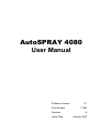
AutoSPRAY 4080
User Manual
Software Version:
Part Number:
Revision
Issue Date:
2.1
1-1282
A
January 2007
Copyright Notice
All rights reserved. No part of this publication may be reproduced, stored
in a retrieval system, or transmitted in any form or by any means,
electronic, mechanical photocopying, recording, or otherwise, without the
prior written permission of Rinex Technology.
Disclaimer
No liability is assumed with respect to the use of the information
contained herein. While every precaution has been taken in the
preparation of this publication, RINEX assumes no responsibility for
errors or omissions, nor is any liability assumed for damages resulting
from the use of the information contained herein. Further this publication
and features described herein are subject to change without notice.
Use of this system is strictly limited to providing steering assistance to
the operator who must remain in control of the vehicle at all times.
RINEX, including its officers servants and agents, does not make any
representation to any party and will not accept any responsibility or
liability whatsoever for any loss or damage of whatever nature suffered
by any such person or corporation choosing or seeking to use this
system or any part thereof.
By use of this system you agree that RINEX is not liable or responsible
for any damage whatsoever to the vehicle, any property, personal
injuries, or death that may result from the use or abuse of this system.
AutoSPRAY 4080 User Manual
Written for AutoSPRAY 4080 software Version 2.1
Publication Date: January 2007
Copyright © 2007 by Rinex Technology. All rights reserved.
Acknowledgements
Windows CE® and Windows XP® are registered to Microsoft Corp.
Other products and trademarks mentioned in this manual are the property of their
registered owners.
RINEX TECHNOLOGY
ABN: 30 029 441 181
AUSTRALIA
NORTH AMERICA
Office Locations :
19 Lyall Street
South Perth WA 6151
Suite 253 919 Centre Street
Calgary AB T2E-2P6
Postal Address :
PO Box 211
South Perth WA 6951
Suite 253 919 Centre Street
Calgary AB T2E-2P6
Telephone :
Local :
(08) 9474 4771
International : +61-8-9474 4771
Local :
International :
(403) 520 0083
+1-403-520 0083
Local :
International :
(403) 520 0086
+1-403 520 0086
Facsimile :
Local :
(08) 9474 4772
International : +61-8-9474 4772
Internet :
http://www.rinex.com.au
http://www.rinextech.com
Email :
[email protected]
[email protected]
RINEX LIMITED WARRANTY
Products
This warranty covers all products (the “Products”) manufactured and or sold by RINEX
Technology or their authorised dealers.
RINEX Technology Limited Warranty
RINEX Technology (“RINEX”) hereby warrants solely to the end purchaser of the Products,
subject to the exclusions and procedures set forth herein below, that the Products sold to
such end purchaser shall be free, under normal use and maintenance, from defects in
material and workmanship for a period of 12 months from delivery. Repairs and replacement
components are warranted, subject to the exclusions and procedures set forth below, to be
free, under normal use and maintenance, from defects in material and workmanship for 90
days from delivery, or for the balance of the original warranty period, whichever is greater.
Purchaser’s Exclusive Remedy
The end purchaser’s exclusive remedy under this warranty shall be limited to the repair or
replacement, at the option of RINEX, of any defective Products or components thereof. The
end user shall notify RINEX or a RINEX authorised dealer immediately of any claimed defect.
Repairs shall be made through RINEX only.
Exclusions
RINEX does not warrant damage occurring in transit or due to misuse, abuse, improper
installation, neglect, alteration, abnormal use, lightning (or other electrical discharge),
exposure to moisture or dampness, excessive temperatures, spill of liquids or fluids, or acts
of God. Repair, modification or service of RINEX products by any party other than an
authorised RINEX dealer shall render this warranty null and void. RINEX does not warrant
any Product where the Product serial number or nameplate has been removed, defaced or
altered. RINEX does not warrant claims asserted after the end of the warranty period.
RINEX does not warrant or guarantee the precision or accuracy of positions obtained when
using Products. The potential accuracy of Products as stated in RINEX literature and/or
Product specifications serves to provide only an estimate of achievable accuracy based on:
• Specifications provided by the US Department of Defence for GPS Positioning,
• GPS OEM Receiver specifications of the appropriate manufacturer (if applicable), and
• DGPS service provider performance specifications.
RINEX reserves the right to modify Products without any obligation to notify, supply or install
any improvements or alterations to existing Products.
No Other Warranties
The foregoing warranty is exclusive of all warranties, whether written, oral, implied or arising
by statute, course of dealing or trade usage, in connection with the design, sale, installation,
service or use of any products or any components thereof, including, but not limited to, any
warranty of merchantability or fitness for a particular purpose.
Limitation of Liability
The extent of RINEX’S liability for damages of any nature to the end purchaser or any other
person or entity whether in contract or tort and whether to persons or property shall in no
case exceed, in the aggregate, the cost of correcting the defect in the Product or, at RINEX’S
option, the cost of replacing the defective item. In no event will RINEX be liable for any loss
of production, loss of profits, loss of use for any special, indirect, incidental, consequential or
contingent damages, even if RINEX has been advised of the possibility of such damages.
Without limiting the foregoing, RINEX shall not be liable for any damages of any kind
resulting from installation, use, quality, performance or accuracy of any products.
RINEX LIMITED WARRANTY
Governing Legislation
To the greatest extent possible, this warranty shall be governed by the laws of the State of
Western Australia. In the event that any provision hereof is held to be invalid by a court of
competent jurisdiction, such provision shall be severed from this warranty and the remaining
provisions shall remain in full force and effect.
Obtaining Warranty Service
In order to obtain warranty service, the end purchaser must bring the Product to an
authorised RINEX dealer along with the end purchaser’s proof of purchase. The end
purchaser must produce the original invoice or other purchase documents as proof of the
purchase date.
The end purchaser is solely responsible for the cost of transportation of the Product to
RINEX or an authorised RINEX dealer and the Product is at the end purchaser's risk whilst in
transit.
For any questions regarding warranty service or to obtain information regarding the location
of any of RINEX’s approved dealers, contact RINEX at the following address:
Rinex Technology
19 Lyall Street
South Perth
Western Australia 6151
Telephone : (08) 9474 4771
Facsimile :
(08) 9474 4772
Internet :
www.rinex.com.au
TABLE OF CONTENTS
AutoSPRAY 4080 User Manual
1 Introduction .......................................................................................1
1.1 AutoSPRAY 4080 Standard Features.......................................................... 3
1.2 Typical Uses of the AutoSPRAY 4080 ......................................................... 4
1.3 AutoSPRAY 4080 Components ................................................................... 5
2 Installation .........................................................................................7
2.1
2.2
2.3
2.4
Installing the AutoSPRAY 4080 ................................................................... 9
Connecting Vehicle Power......................................................................... 10
Connecting the Spray Rate Controller ....................................................... 12
Connecting the GPS .................................................................................. 13
3 Getting Started ................................................................................15
3.1
3.2
3.3
3.4
3.5
3.6
3.7
3.8
3.9
4
Using AutoSPRAY..........................................................................43
4.1
4.2
4.3
4.4
4.5
5
Powering the System ................................................................................. 17
The Front Panel ......................................................................................... 18
The Back Panel ......................................................................................... 20
Configuring the GPS.................................................................................. 21
Configuring the Spray Rate Controller ....................................................... 24
Configuring the Vehicle and Boom ............................................................ 25
Measuring Vehicle & Boom offsets ............................................................ 27
Configuring the Boom Spray Parameters .................................................. 36
Self Test the AutoSPRAY 4080 ................................................................. 41
Modes of Operation ................................................................................... 45
Using AutoSPRAY to Spray a Field ........................................................... 47
Starting a New Field .................................................................................. 49
Creating Field Zones ................................................................................. 50
Using Manual Override .............................................................................. 52
The Menu System...........................................................................53
5.1
5.2
5.3
5.4
5.5
5.6
5.7
5.8
5.9
5.10
Navigating the Menus ................................................................................ 55
The Menu Hierarchy .................................................................................. 56
The Display Menu...................................................................................... 58
The Boom Width Menu .............................................................................. 59
The Vehicle Menu...................................................................................... 60
The GPS Menu .......................................................................................... 61
The Parameters Menu ............................................................................... 62
The Boundary Menu .................................................................................. 64
The Setup Menu ........................................................................................ 66
The System Menu...................................................................................... 67
TABLE OF CONTENTS
Appendices ..........................................................................................69
Appendix A
Appendix B
Appendix C
Appendix D
Appendix E
Appendix F
Appendix G
Appendix H
Appendix I
Appendix J
Glossary...................................................................................... 70
AutoSPRAY 4080 Options .......................................................... 71
System Messages....................................................................... 72
Troubleshooting .......................................................................... 74
Resetting the System .................................................................. 77
Connector Pin-Outs..................................................................... 79
Specifications.............................................................................. 80
Setting up for Flexi-Coil SP655 ................................................... 81
Configuring the EZ-Guide®......................................................... 82
Configuring the Outback®........................................................... 83
Index ......................................................................................................84
1
Introduction
Welcome to the AutoSPRAY 4080 User Manual. This document
describes how to use the AutoSPRAY 4080 system.
The AutoSPRAY 4080 system is designed to connect to your existing
Spray Controller and GPS guidance system to provide automatic boom
section control. This will greatly reduce the need for manually switching
sections ON or OFF when going over previously sprayed crop or
pasture. Its ability to automatically control the spraying state of the
sections relieves the operator from an arduous task which requires split
second timing on multiple switches. Unlike other AutoSPRAY models
which were incorporated with the guidance system the AutoSPRAY 4080
is an autonomous system which can be interfaced with most existing
spray rate controllers and GPS receivers.
This manual is designed to assist users of the AutoSPRAY 4080 in the
operational use of the AutoSPRAY 4080 hardware and software.
AutoSPRAY 4080 User Manual
Page 2
Version 2.1
Revision A
1.1 AutoSPRAY 4080 Standard Features
Timing Delays
The AutoSPRAY 4080 can be adjusted for delays
from electrical to mechanical switching.
Variable Overlap
Allows the operator to configure the required
overlap.
Vehicle Modeling
Allows the operator to accurately define vehicle
and boom dimensions.
Antenna Offsets
Allows the operator to define the GPS antenna
offsets.
Standby Mode
Allows the operator to disable AutoSPRAY to
allow the spray controller to be operated manually.
Inclusion &
Exclusion zones
Allows the operator to set boundaries for the
spraying operation.
Manual Override
Allows the operator to manually select boom
sections to be ON or OFF, overriding AutoSPRAY.
AutoSPRAY 4080 User Manual
Page 3
Version 2.1
Revision A
1.2 Typical Uses of the AutoSPRAY 4080
Spraying around obstacles
Automatically minimise over spray
around trees or rock heaps.
AS4080 detects areas previously
sprayed and shuts down sections
and reactivates as necessary.
Spraying headlands
AS4080 detects areas previously
sprayed as the headlands are
approached and shuts down
sections and reactivates as
necessary.
AutoSPRAY 4080 User Manual
Page 4
Version 2.1
Revision A
1.3 AutoSPRAY 4080 Components
When you receive your AutoSPRAY 4080 system, please check that you
have received all of the components detailed on the packing list. See
below for a list of components supplied.
Quantity Description
Part Nō.
1
1
1
AutoSPRAY 4080 Controller
Mounting kit
Power cable
1-0480
1-0212
1
1
1
AutoSPRAY 4080 User Manual
AutoSPRAY 4080 Quick Start Card
GPS interface cable
1-1250
1-1315
1
Generic spray rate controller cable
"
"
"
Inspect all items for visual damage. If any component appears to be
damaged, contact your supplier immediately. Ensure all packaging and
shipping details are kept for future reference.
It is important the spray rate controller adaptor cable ordered matches
your spray rate controller. Using the wrong cable may damage your
spray rate controller or the AutoSPRAY 4080 controller.
"Variants of these cables are available. Refer to Appendix B for a
list of cables customised to your particular installation.
AutoSPRAY 4080 User Manual
Page 5
Version 2.1
Revision A
AutoSPRAY 4080 User Manual
Page 6
Version 2.1
Revision A
2
Installation
This section describes how to connect and install the components of the
AutoSPRAY 4080 system.
A schematic of the AutoSPRAY 4080 and how it connects to the spray
rate controller and GPS receiver is shown in Figure 2.1
Figure 2.1
Schematic layout of the AutoSPRAY 4080
It is recommended that all electrical wiring should be
installed by a qualified auto-electrician. Incorrect
wiring may damage the AutoSPRAY 4080 controller,
the spray rate controller, or both.
AutoSPRAY 4080 User Manual
Page 8
Version 2.1
Revision A
2.1 Installing the AutoSPRAY 4080
Prior to installing the AutoSPRAY 4080 system, it is recommended that
the operator reviews Chapter 3 to familiarise themselves with the
individual components of the system.
Step Instruction
1
2
3
4
5
6
7
Attach the mounting plate, P/n 1-0213 to the underside of the
AutoSPRAY 4080 controller with the supplied screws..
Install the AutoSPRAY 4080 Controller in a suitable location in
the vehicle to allow the operator to have access to the keypad.
The location should not impede upon the vision of the operator
or restrict access to any vehicle controls. Four screws are
provided to mount the controller to the vehicle. Ensure that the
Isolation Power Switch (IPS) on the AutoSPRAY 4080 controller
is in the OFF (O) position.
Route the DC power cable from the vehicle’s battery to the
AutoSPRAY 4080 controller. Connect the DC power cable to the
battery and ignition line. Further details on connecting the power
cable is described in Section 2.2.
Route the supplied spray rate controller cable from the spray rate
controller to the AutoSPRAY 4080 controller. Connect the cable
to the spray rate controller. Further details on connecting the
spray rate controller cable are contained in Section 2.3.
Route the GPS Interface cable from the GPS guidance system to
the AutoSPRAY 4080 controller. Connect the cable to the GPS
receiver. Further details on connecting the GPS Interface cable
are contained in Section 2.4.
Ensure that the vehicle ignition is OFF. Use the Isolation Power
Switch (IPS) to power on the AutoSPRAY 4080 controller to
check that the power cable has been correctly installed. Note! –
The unit will not power up completely at this time.
Power Status LED on the keypad should display in RED
Power Off the controller using the IPS.
AutoSPRAY 4080 User Manual
Page 9
Version 2.1
Revision A
2.2 Connecting Vehicle Power
The RINEX power cable (P/N 1-2406) is a three core power cable which
allows the AutoSPRAY 4080 controller to be connected directly to the
vehicle's battery. The cable can be connected directly to a 12vDC battery
supply without the need for any additional step-down converters.
RED
Positive wire with in-line fuse connects to the vehicle
battery positive terminal (12 vDC ONLY), fitted with a M12
ring connector.
BLACK
Ground wire connects to the vehicle battery negative
terminal, fitted with a M12 ring connector.
ORANGE Positive wire connects to the vehicle ignition ON circuit.
The wire is connected into the vehicle's ignition circuit such
that the AutoSPRAY 4080 will detect when the ignition is
switched on and off.
" The RINEX power cable is assembled within split tubing to
allow the orange wire to be separated at any point to allow for
in-cab termination.
The cable should be routed from the operator's cab to the vehicle's
batteries through a dedicated cable gland. If necessary an exit hole will
have to be drilled into the vehicle which should be fitted with a rubber
grommet to protect the cable from rubbing directly on the vehicle wall.
The hole should be sealed with the supplied silicone sealant to prevent
dust and moisture from entering the cab.
Customized Power Connector Cables
It is possible to order customized power connection cables to simplify the
installation of the AutoSPRAY 4080. Cables are available for the John
Deere power strip connection and the universal thee pin circular
connector. Both connectors provide direct battery power and the ignition
circuit power. Refer to Appendix B for optional cable information.
DC Power Cautionary Notes
The RINEX power cable supplied should only be connected
AutoSPRAY 4080 User Manual
Page 10
Version 2.1
Revision A
directly to the battery with the supplied fuse in place. We
strongly recommend NOT removing the supplied fuse. If a
power wire should short to the vehicle body, a battery can
supply a current that will heat the wire to the point where the
insulation will catch fire. A fuse mounted inline near the battery
connection point and before the cable passes through the
vehicle panel will prevent the risk of a vehicle fire.
The RINEX power cable should not be connected to the input or
output terminals of a step-down converter in a 24v DC system
as typically the converter will effect system performance.
The RINEX power cable should not be connected directly to the
battery if the vehicle is equipped with a battery isolator switch.
In these cases the negative wire (black) should be connected to
the vehicle side of the isolator.
AutoSPRAY 4080 User Manual
Page 11
Version 2.1
Revision A
2.3 Connecting the Spray Rate Controller
A generic spray rate controller cable is supplied with the AutoSPRAY
unless a specific cable was ordered at the time of purchase. Preassembled cables which plug directly from the AutoSPRAY 4080
controller to spray rate controllers such as a Raven 440/450, Farmscan
24V1, or a TeeJet 844 can be ordered with the system.
See Appendix B – AutoSPRAY 4080 Options for available spray rate
controller cables. Each cable kit is supplied with comprehensive
installation instructions.
When the spray rate controller cable has been installed, connect the 16
pin AMP circular connector the AutoSPRAY 4080 back panel.
To test Spray Rate Controller cable, follow the steps below.
Step Instruction
1
2
3
4
5
6
Ensure that the Isolation Power Switch (IPS) is in the ON
position. Turn the vehicle ignition on to start the AS4080 system.
The DISPLAY menu will be shown. This displays the status of
the Master Control switch, and the state of the configured
sections.
Switch the selected Master Control switch to ON.
The display should change to M=on. The change should be
shown on the Spray Controller display.
Switch the selected Master Control switch to OFF.
The display should change to M=off. The change should be
shown on the Spray Controller display.
A delay may occur between the switching of the Master Control switch
and when the M= value is changed on the AutoSPRAY 4080. This delay
is due to the type of electrical circuit switching used within the Spray
Rate Controller.
If Status M= value does not change, check that the cable has been
installed correctly.
AutoSPRAY 4080 User Manual
Page 12
Version 2.1
Revision A
2.4 Connecting the GPS
A GPS receiver or guidance system with an incorporated GPS needs to
be connected to the AutoSPRAY 4080 using a serial interface.
An interface cable is supplied with the AutoSPRAY 4080 kit, which will
suit most GPS receivers. However it is possible that a different cable will
be required to connect the GPS receiver to the AutoSPRAY 4080. See
Appendix B for common GPS receiver interface cables.
The GPS output messages required are NMEA GGA and VTG at 5Hz.
The default baud rate is 19,200 but can be changed if required.
You will need to refer to your GPS system User Manual to assist in
determining data port settings.
To test the GPS interface, follow the steps below.
Step
Instruction
1
With the Isolation Power Switch (IPS) ON, turn the
vehicle ignition ON.
2
to show the DISPLAY menu,
Use
then
to move to the GPS Status
option.
The Sats= displays the number of satellites currently
being observed.
If the number is equal to 0 (zero), then GPS may be
incorrectly configured.
3
GPS Accuracy – An Important Issue
The relative accuracy of your GPS system will determine the overall
performance of the AutoSPRAY 4080 system. The more accurate the
GPS, the more accurate AutoSPRAY will be.
By default the AutoSPRAY 4080 is configured to function only with a
differentially corrected GPS position (DGPS). Typically DGPS is quoted
with sub-metre accuracy, hence the AutoSPRAY will be of an equivalent
accuracy.
AutoSPRAY 4080 User Manual
Page 13
Version 2.1
Revision A
The AutoSPRAY 4080 can be configured to function with non-corrected
GPS positioning, or sometimes referred to as stand-alone GPS. The
resultant accuracy of the AutoSPRAY 4080 will once again be directly
related to the GPS signal.
RINEX recommend that the AutoSPRAY 4080 always be used with a
DGPS to provide optimal accuracy with the overall system, it is the
operator’s responsibility to determine the accuracy of the GPS.
"
Check with your supplier of the GPS receiver or guidance
system to determine to overall accuracy you should expect.
"
See also Section 3.4 for further information.
AutoSPRAY 4080 User Manual
Page 14
Version 2.1
Revision A
3
Getting Started
This section details the steps taken for the first time user of the overall
system. In particular this section describes the correct way in which to
power the system ON and OFF.
In addition, this section describes the front and rear panels of the
AS4080 Spray Controller, and contains instructions on configuring the
AS4080 for the correct GPS and spray controller settings.
Furthermore this section describes the necessary information, which
includes measurements on the vehicle to ensure that the system will
function correctly.
AutoSPRAY 4080 User Manual
Page 16
Version 2.1
Revision A
3.1 Powering the System
Prior to this step the AutoSPRAY 4080 system should be completely
installed into the vehicle in accordance with the installation instructions
(See Section 2 of this manual).
1. Turn the Isolation Power Switch (IPS) on the AutoSPRAY 4080
controller box to the ON position (-). This will not immediately
power the system as the vehicle ignition must also be ON. See
Figure 3-1 to locate the IPS.
2. With the IPS on the AutoSPRAY 4080 controller in the ON position,
start the vehicle and leave the engine running. The AutoSPRAY
4080 will start to power on after approximately one minute.
ISOLATION
POWER
SWITCH
Figure 3-1 : AutoSPRAY 4080 Controller & IPS
3. To shut the AutoSPRAY 4080 Controller OFF, simply turn the
vehicle ignition off. This will shutdown the AutoSPRAY 4080
Controller and power down the system. The IPS should not be
switched to the OFF position.
In normal operation, leave the Isolation Power
Switch (IPS) on the AutoSPRAY 4080 controller in
the ON position (-) at all times. Use the vehicle
ignition switch to turn the AutoSPRAY 4080 ON and
OFF, the IPS should only be turned OFF if the
AutoSPRAY 4080 is not required to be operational
for an extended period.
AutoSPRAY 4080 User Manual
Page 17
Version 2.1
Revision A
3.2 The Front Panel
The front panel of the AutoSPRAY 4080 consists of an LCD screen and
a keypad to operate the system. The components of the front panel are
described below.
GPS
Status
Power
Status
LCD
Screen
Standby
Button
Enter
Button
Up
Button
Down
Button
Left
Button
Right
Button
Figure 3-2 : The AutoSPRAY 4080 Front Panel
AutoSPRAY 4080 User Manual
Page 18
Version 2.1
Revision A
Component
Description
LCD Screen
Left Button
A two line LCD screen, used to display
program menus.
GPS Status LED
Green – Good DGPS
Orange – Poor DGPS
Red
– No DGPS
Off
– No Data
See page 23 for more details on GPS Status.
Power LED
Green – AutoSPRAY operational
Orange – Standby Mode
Red
– Power connected but unit is off.
Off
– No power connected
Press to enter Standby Mode or alternatively
used as a master switch when the Control
setting is set to keypad.
Press to move between menus or to change
setting values.
Press to move between menus or to change
setting values.
Press to move left in a menu.
Right Button
Press to move right in a menu.
Enter Button
Press to select a menu item for editing.
Press to save setting after editing.
GPS Status
Power Status
Standby Button
Up Button
Down Button
AutoSPRAY 4080 User Manual
Page 19
Version 2.1
Revision A
3.3 The Back Panel
The back panel of the AutoSPRAY 4080 is used to connect to the spray
controller and to the external GPS source among other peripherals. The
components of the back panel are described below.
GPS
Port
Power
Connector
Toggle
Switch
Port
Spray Rate
Controller
Connector
Fuse
USB Port
External
Speaker Jack
Isolation Power
Switch
Figure 3-3 : The AutoSPRAY 4080 Back Panel
Component
Description
GPS Port
Used to connect external GPS input.
Toggle Switch Port
Used to connect the toggle switch used to
turn the master on/off.
5A quick blow fuse.
Fuse
USB Port
Isolation Power Switch
(IPS)
Spray Rate Controller
Connector
Power Connector
AutoSPRAY 4080 User Manual
Used to connect USB devices such as
memory drives or the RINEX button box used
turn the Master switch ON or OFF.
The IPS totally removes power from the
controller; if the vehicle is started the
AutoSPRAY 4080 will not start.
Used to connect to the spray controller.
Used to connect to power input (12vDC).
Page 20
Version 2.1
Revision A
3.4 Configuring the GPS
The AutoSPRAY 4080 will operate with almost any GPS receiver which
can output a NMEA message. In order for the AutoSPRAY 4080 to
function correctly the GPS receiver must be configured to the following
parameters;
NMEA message
GGA & VTG
Update rate
5Hz
Baud rate
19,200 baud (optional settings)
Instructions for configuring the Trimble EZ-Guide ® and Outback® GPS
Guidance are provided in Appendices I & J. For all other GPS receivers
or guidance system refer to the manufacturers manual.
Connect the GPS receiver to the GPS port on the back panel of the
AutoSPRAY 4080 Controller as described in Section 2.4. Once the GPS
has been connected it will be necessary to check that the GPS
messages are being correctly received by the AutoSPRAY 4080
controller.
Configuring the GPS Baud Rate
It is important that the AutoSPRAY 4080 is
configured with the correct GPS baud rate.
Select the correct baud rate according to your
GPS receiver by editing the Baud value in the GPS Menu.
Connecting GPS
The GPS is connected via a serial cable from the GPS receiver to the
GPS port on the Back Panel of the AutoSPRAY 4080. See Figure 3-3 on
page 20.
GPS Status
The GPS Status displays the number of
satellites that are observed and the current
HDOP (Horizontal accuracy indicator).
AutoSPRAY 4080 User Manual
Page 21
Version 2.1
Revision A
For Good GPS, the number of satellites must be greater than 4.
For Good GPS the HDOP should be less than 10.0. A HDOP of greater
than 10.0 will result in Poor GPS.
DGPS Requirements
The AutoSPRAY 4080 by default requires differentially corrected GPS
(DGPS) data which provides a more accurate position and enhances the
overall performance of the system. However the AutoSPRAY 4080 can
be configured to operate on GPS data only, which is done by editing the
DGPS Required Menu.
GPS Health
The GPS Health is constantly indicated on the GPS status LED as
denoted by the colour of the LED. Further information on the GPS health
is also provided on the screen by a series of status messages.
AutoSPRAY 4080 User Manual
Page 22
Version 2.1
Revision A
GPS Health Messages
Status
LED
Description
Good GPS
No DGPS
Green
Red
Poor GPS
Orange
No Time
Blank
No Pos
Blank
No NMEA
No Data
Blank
Blank
Good DGPS data being received.
Good GPS data is being received but no
differential correction signal is received.
Poor DGPS data is received, < 4 satellites or
PDOP > 10. AS4080 will not function
Correct data type & baud rate, no GPS time
or position.
Correct data type & baud rate, no GPS
position.
Invalid data being received.
There is no data being received through the
GPS port.
In order for the AutoSPRAY 4080 to be operational the GPS LED must
be Green if the DGPS Required option is set to YES. If the DGPS
Required option is set to NO the GPS LED can be Red or Green.
GPS Alarms
The AutoSPRAY 4080, when in the OPERATIONAL mode with the
Master Control switch ON, will provide an audible alarm in the following
situations:
•
DGPS Required YES
Whenever the LED changes state from GREEN
•
DGPS Required NO
Whenever the LED changes state from RED or GREEN
The cause of the alarm should be investigated, and rectified, before
continuing to use the AutoSPRAY 4080.
AutoSPRAY 4080 User Manual
Page 23
Version 2.1
Revision A
3.5 Configuring the Spray Rate Controller
The spray rate controller may not need to be configured to operate with
the AutoSPRAY 4080. However it is necessary that one switch is
selected as the Master switch, which controls when both the AutoSPRAY
4080 and the spray rate controller should be ON or OFF.
When the AutoSPRAY 4080 is in OPERATIONAL MODE (controlling the
section switches), the individual boom section switches are to be in the
OFF position.
Selecting the Spray Rate Controller
The AutoSPRAY 4080 can be configured to
work with different types of spray rate
controllers. From the Parameters menu, select
the required controller from the options available. The Default option will
suit most generic spray rate controllers.
Master Control
The Master Control setting is used to determine which device will be
used to control the master on/off. The selections are as follows:
Control Setting
Device Used
Toggle
The Toggle Switch (optional device),is
connected to the Toggle Switch port on the
back panel.
The Master switch on the spray rate
controller.
The Standby Button on the front panel
keypad of the AutoSPRAY 4080 controller.
The RINEX Button Box (optional device), is
connected to the USB port on the back
panel.
External
Keypad
Button Box
Select the appropriate device via the
Control setting in the Parameters Menu.
AutoSPRAY 4080 User Manual
Page 24
Version 2.1
Revision A
3.6 Configuring the Vehicle and Boom
When setting up the AutoSPRAY 4080 for the first time or for use in a
new vehicle, there are various settings that must be configured for
AutoSPRAY 4080 to function correctly and accurately.
The AutoSPRAY 4080 models the movement of the entire spray rig,
whether it is a self propelled boom spray or a trailed boom spray. This
allows the true position of the spray boom and its orientation to be
accurately computed for precise control when switching the boom
sections ON and OFF.
The measurements as detailed in the following section are to be
accurately measured on the spray rig and should be recorded in the
accompanying Table for the vehicle type for future reference.
GPS Offset (Cross Track)
The distance between the centreline of the
vehicle and the GPS antenna must be
entered as the Cross Track value. Measure
the distance and enter a positive value if the antenna is to the right of the
centreline of the vehicle as viewed from the rear of the tractor facing
forwards. Enter a negative value if the antenna is to the left of the
centreline of the vehicle as viewed from the rear of the tractor facing
forwards. The Cross Track value can be edited in the GPS Menu.
GPS Offset (Long Track)
The distance from the GPS antenna to the centreline of the front axle on
the spray vehicle. If a front boom is used the Long Track measurement is
to the flow point of the boom and not the front axle.
Boom Settings
The Boom Settings determine the overall width
of the spray boom being used. Enter the
number of boom sections and the width of
each section in the Boom Width Menu.
AutoSPRAY 4080 User Manual
Page 25
Version 2.1
Revision A
Link and Axle Distances
The Link and Axle distances are used when determining the path of the
spray rig as it moves around the field.
The Link and Axle distances should be measured as follows:
Link Setting
Measurement
Link 1
Link 1 is measured from the front axle
centreline to the vehicle hitch point.
Axle 1 is measured from the rear axle of
Link 1 to the hitch point of Link 1.
Link 2 is measured from the hitch point of
Link 1 to the hitch point or the flow point if it
is the last link.
Axle 2 is measured from the rear axle of
Link 2 to the pivot point of Link 2.
Link 3 is measured from the hitch point of
Link 2 to the flow point.
Axle 3 is measured from the rear axle of
Link 3 to the flow point.
Axle 1
Link 2
Axle 2
Link 3
Axle 3
See Section 3.7 for an illustration of the Link Settings for different vehicle
types.
The number of Links and the Link and axle distances can be edited in
the Vehicle Menu
AutoSPRAY 4080 User Manual
Page 26
Version 2.1
Revision A
3.7 Measuring Vehicle & Boom offsets
For precise control of the AutoSPRAY 4080 it is necessary that all
measurements are accurately recorded and entered into the system.
Some of the measurements required will be unique to the vehicle
configuration, a self-propelled sprayer or tow behind, and the following
diagrams indicate the measurements required.
Select the type of vehicle and record the settings necessary on the
accompanying pages.
AutoSPRAY 4080 User Manual
Page 27
Version 2.1
Revision A
Self-Propelled Vehicle
Figure 3-9 – Self Propelled Vehicle
AutoSPRAY 4080 User Manual
Page 28
Version 2.1
Revision A
Self-Propelled vehicle settings
Vehicle Measurements
Number of Links
1
Link 1
Axle 1
Cross track
Long track
Boom Details *
Number of Sections
*NOTE :
Section 1
Section 5
Section 2
Section 6
Section 3
Section 7
Section 4
Section 8
Enter the number of sections, and the width of each section in the overall
configuration.
Boom Spray Parameters
Master Control
Tolerance
Search Width
Latency On
Latency Off
AutoSPRAY 4080 User Manual
Page 29
Version 2.1
Revision A
Tow Behind Vehicle
Figure 3-10 – Vehicle Measurements
AutoSPRAY 4080 User Manual
Page 30
Version 2.1
Revision A
Tractor with tow behind boom spray settings
Vehicle Measurements
Number of Links
Link 1
Axle 1
Link 2
Axle 2
Link 3
Axle 3
Cross track
Long track
*NOTE : Enter the link and axles which correspond to the number of Links in the
overall configuration.
Boom Details *
Number of Sections
*NOTE :
Section 1
Section 5
Section 2
Section 6
Section 3
Section 7
Section 4
Section 8
Enter the number of sections, and the width of each section in the overall
configuration.
Boom Spray Parameters
Master Control
Tolerance
Search Width
Latency On
Latency Off
AutoSPRAY 4080 User Manual
Page 31
Version 2.1
Revision A
Self-Propelled Vehicle (front mounted boom)
Figure 3-12 – Vehicle Measurements
AutoSPRAY 4080 User Manual
Page 32
Version 2.1
Revision A
Self-Propelled vehicle settings (front mounted boom)
Vehicle Measurements
Number of Links
1
Link 1
Axle 1
Cross track
Long track
0.0m
*NOTE : Enter the link and axles which correspond to the number of Links in the
overall configuration.
Ensure that the Front Boom is set to YES in the Vehicle Menu.
The Long Track must be entered as a negative value.
Boom Details *
Number of Sections
*NOTE :
Section 1
Section 5
Section 2
Section 6
Section 3
Section 7
Section 4
Section 8
Enter the number of sections, and the width of each section in the overall
configuration.
Boom Spray Parameters
Master Control
Tolerance
Search Width
Latency On
Latency Off
AutoSPRAY 4080 User Manual
Page 33
Version 2.1
Revision A
Articulated Tractor with Tow-behind
Figure 3-13 – Vehicle Measurements
"Axle1 measurement is the same as Link1 value for this vehicle
type.
AutoSPRAY 4080 User Manual
Page 34
Version 2.1
Revision A
Articulated Tractor with tow behind boom spray settings
Vehicle Measurements
Number of Links
Link 1
Axle 1
Link 2
Axle 2
Link 3
Axle 3
Cross track
Long track
*NOTE : Enter the link and axles which correspond to the number of Links in the
overall configuration.
The Axle1 value is the same as the Link1 measurement for this vehicle
type.
Boom Details *
Number of Sections
*NOTE :
Section 1
Section 5
Section 2
Section 6
Section 3
Section 7
Section 4
Section 8
Enter the number of sections, and the width of each section in the overall
configuration.
Boom Spray Parameters
Master Control
Tolerance
Search Width
Latency On
Latency Off
AutoSPRAY 4080 User Manual
Page 35
Version 2.1
Revision A
3.8 Configuring the Boom Spray Parameters
The following parameters are used when determining when to turn the
sections ON and OFF. To optimize the usage of AutoSPRAY 4080 it is
important that these settings are configured correctly.
Tolerance
The Tolerance is used to decide when to turn valves ON or OFF. When
set to its default of 1%, the system will turn the valves on whenever any
part of the sensed area has not been sprayed. It is effectively the percent
of miss that the system will tolerate. If the value is increased, the system
will not turn the valves on when traversing over a small missed area such
as a line between two spray swaths.
The Tolerance value can be edited in the
Parameters Menu.
Search Width
NOTE: This is an advanced tuning parameter and should only be
changed from its default value under instruction from authorised support
personnel.
This value defines the amount of overlap allowed when turning the
valves ON before leaving a sprayed area such as an end zone. Hence if
the value is set to 2m (default) the spray section should turn on 2m
before any part of the section reaches and unsprayed area. This can be
used to decrease errors caused by inaccurate GPS positioning. When
entering a previously sprayed area, the system will attempt to turn OFF
at exactly the correct time.
The Search Width value can be edited in the
Parameters Menu.
Latency ON
Latency ON is used to compensate for any time delay between the time
the system requests the valves to open and the actual time that this
AutoSPRAY 4080 User Manual
Page 36
Version 2.1
Revision A
takes place. For example, if it takes one second for a valve to open, a
Latency ON value of one second should be entered. In this case the
signal to open the valve will be sent one second before the valve needs
to open.
Latency OFF
Latency OFF is opposite to Latency ON and is used to compensate for
any time delay between the time the system requests the valves to close
and the actual time that this takes place.
Latency Off
time (seconds)
Latency On
time (seconds)
MCS On
Valves Open
jets-spraying
MCS Off
Valves Closed
jets-not spraying
Figure 3-13: AutoSPRAY 4080 Latency values
AutoSPRAY 4080 User Manual
Page 37
Version 2.1
Revision A
Measuring Latency
The quickest way to estimate the latency of the sprayer is to use a stop
watch, turn a spray section on and time the delay between this action
and when spray is coming out the nozzle onto the crop. This may be a
very small value (a few tenths of a second and hard to measure
accurately).
For a more accurate measurement, use the following procedure:
Step Instruction
1
2
3
4
Diagram
Drive slowly in a straight line down the
field for 200m with the sprayer on. The
tank should have water only for the
purpose of this exercise.
Have another person mark the end
nozzle of the boom with two pegs and a
rope half way along the spray run.
At right angles to the pervious spray run,
spray at 20km/hr across the spray mark
with one end of the boom crossing over
the rope.
Ensure that you have allowed enough
distance before crossing over the line for
the boom trailer to straighten up behind
the tractor.
Have someone measure the distance
from the rope to where the sprayer
actually reacted.
Repeat step 2 in the opposite direction.
Metric Calculations
If Speed(km/h) = The speed of the vehicle in kilometres per hour
AutoSPRAY 4080 User Manual
Page 38
Version 2.1
Revision A
Step Instruction
5
6
Diagram
Distance(m) = The distance from the rope to where the sprayer
reacted in metres.
Calculate the latency using this formula:
Latency(s) = Distance(m) ÷ Speed(km/h) x 3.6
For example
Assuming the operator was traveling at 20km/hr and the
distance from the rope to where the sprayer reacted is 5 metres:
Latency(s) = 5(m) ÷ 20(km/h) x 3.6 = 0.9 seconds.
Imperial Calculations
If Speed(mph) = The speed of the vehicle in miles per hour.
Distance(ft) = The distance from the rope to where the sprayer
reacted in feet.
Calculate the latency using this formula:
Latency(s) = Distance(ft) ÷ Speed(mph) x 0.68
For example
Assuming the operator was traveling at 12mph and the distance
from the rope to where the sprayer reacted is 16ft:
Latency(s) = 16(ft) ÷ 12(mph) x 0.68 = 0.9 seconds
Often the latency time for the sprayer to switch on will differ from
the time to switch off. Enter each value into the Latency ON and
Latency OFF menu options.
Repeat steps 1 to 4, altering the latency figure by plus or minus
0.1 seconds, until the optimum result is achieved.
AutoSPRAY 4080 User Manual
Page 39
Version 2.1
Revision A
The following examples show possible scenarios and how to resolve the
latency settings for optimum control of the AutoSPRAY 4080.
Latency set too low
Latency set too high
Optimum Latency setup
Abnormal situation, increase
search width
AutoSPRAY 4080 User Manual
Page 40
Version 2.1
Revision A
3.9 Self Test the AutoSPRAY 4080
Prior to using the AutoSPRAY 4080 for the first time the AutoSPRAY
4080 Self Test should be completed to ensure that all components are
correctly installed and operational.
The Self Test is used to check the AutoSPRAY 4080 is communicating
correctly with the spray controller. It starts with a test of system sound
and then turns ON each section for three seconds each. To start the
Self Test, set the Self Test Page to “Yes”. The left most boom section
(when looking from behind the boom) will come on first. When the
section test is finished it tests the Master for general ON/OFF switching.
"The Self Test Function is accessible only after turning the
Master on.
AutoSPRAY 4080 User Manual
Page 41
Version 2.1
Revision A
AutoSPRAY 4080 User Manual
Page 42
Version 2.1
Revision A
4
Using AutoSPRAY
This section describes the modes of operation when using the
AutoSPRAY 4080 and also contains a guide on how to spray a field
using the AutoSPRAY 4080.
AutoSPRAY 4080 User Manual
Page 44
Version 2.1
Revision A
4.1 Modes of Operation
The AutoSPRAY 4080 has two modes of operation, STANDBY and
OPERATIONAL. In addition to this the AutoSPRAY 4080 has two nonoperational modes, OFF and NON-POWERED.
The Power LED on the front panel of the AUTOSPRAY 4080 will indicate
the mode of operation. The following notes describe the various modes.
Mode
LED
Operation
NONPOWERED
Blank
OFF
Red
STANDBY
Orange
The AutoSPRAY 4080 is not powered at all
when the unit is either not connected to a DC
power supply or the Isolation Power Switch is
OFF.
The AutoSPRAY 4080 is connected to a
power supply and the Isolation Power Switch
is ON. Once the AutoSPRAY 4080 senses
12vDC on the ignition wire the unit will switch
ON to the OPERATIONAL mode.
When the system is in STANDDBY mode, the
spray controller can be used to manually
control the sections. The LCD will display
STANDBY MODE. Press the Standby Button
on the front panel keypad to enter STANDBY
Mode. Press it again to enter OPERATIONAL
mode.
When the system is not in STANDBY mode, it
is in OPERATIONAL mode. When in
OPERATIONAL mode, the AutoSPRAY 4080
records treatment data as the field is sprayed
and uses this information to turn the boom
sections ON and OFF accordingly.
OPERATIONAL Green
" In STANDBY mode the AutoSPRAY 4080 does not record any
spraying completed when in this mode. STANDBY mode is used
when the operator wishes to manually override the AutoSPRAY
4080
AutoSPRAY 4080 User Manual
Page 45
Version 2.1
Revision A
" In OPERATIONAL Mode the LCD will display the menus which
can be navigated. When the Master switch is ON and treatment
data is being recorded, configuration settings cannot be edited.
AutoSPRAY 4080 User Manual
Page 46
Version 2.1
Revision A
4.2 Using AutoSPRAY to Spray a Field
The following is a step by step guide to commence spraying a field using
the AutoSPRAY 4080.
Step
Instruction
1
Start the AutoSPRAY 4080 by turning the vehicle ignition ON.
Wait until the LCD on the front panel is operational and displays
the menu (This may take approximately one minute.).
Check that the Power and GPS LEDs on the AutoSPRAY 4080
front panel are green.
Turn the spray rate controller ON, all boom section switches are
to be in the OFF position.
Turn the spray rate controller Master switch to the ON position.
2
3
4
5
6
7
8
9
Start to move the vehicle forwards. The boom sections will
automatically switch ON as the vehicle moves over a nontreated area and will switch OFF over a treated area which has
been recorded by the AutoSPRAY 4080.
As the field is being treated, various
status information can be viewed
from the Display Menu. Information
such as area treated and the percentage of overlapped area
can be viewed in this menu.
When the field has been treated, turn the Master switch OFF.
If you wish to stop working, simply turn the vehicle ignition off to
shutdown the AutoSPRAY 4080.
If you wish to continue working in a different field, see section
4.3 on starting a New Field.
Reversing the Vehicle
The AutoSPRAY 4080 typically assumes that the vehicle is always
moving in a forward direction and that the boom sprayed is towed from
the rear of the tractor. The vehicle modelling features incorporated in the
AutoSPRAY4080 uses this logic to compute the position of the boom.
AutoSPRAY 4080 User Manual
Page 47
Version 2.1
Revision A
However when a tractor reverses, such as reversing the boom into a
corner of a field, the AutoSPRAY 4080 will only be aware that the vehicle
is reversing if the Master Switch is in the OFF position. This will be
confirmed by an audible alarm (series of short beeps).
Hence the logic rule that applies is as follows:
If the Master switch is ON the vehicle is moving forward. If the Master
switch is OFF, the vehicle can be moving backwards.
When moving the vehicle into the field to start spraying, the AutoSPRAY
4080 should only be powered up when the vehicle is moving forwards, or
is about to move in a forward direction.
AutoSPRAY 4080 User Manual
Page 48
Version 2.1
Revision A
4.3 Starting a New Field
When a field has been sprayed, it is important that the field is reset to
begin spraying a new field.
To reset the field, hold down the Standby Button on the front panel
keypad for a few seconds until the screen displays “Clearing…”. The
message “Treatment Clear” will be displayed when the field has been
successfully cleared.
" All data in the field will be lost when the field is reset.
AutoSPRAY 4080 User Manual
Page 49
Version 2.1
Revision A
4.4 Creating Field Zones
The AutoSPRAY 4080 can be used to create zones within a field which
can be set as an exclusion, or inclusion zone. The inclusion zone
defines where the AutoSPRAY 4080 will permit spraying activities, ie the
field which is being sprayed. The exclusion zone defines areas where
the AutoSPRAY 4080 will prevent spraying activities, ie may be used to
prevent spray in a water course. An example of a field divided into
zones is shown in Figure 4.1.
WATER
COURSE
INCLUSION
ZONE
EXCLUSION
ZONE
Figure 4.1 Field with Inclusion and Exclusion Zones
As the spray boom crosses into the exclusion zone all sections will be
shut OFF by the AutoSPRAY 4080. The sections will be switched ON
once the spray boom returns to the inclusion zone.
Zone boundaries are created by first choosing the zone type, and then
driving around the perimeter of the zone with the vehicle. The zone
status must be set to RECORD while the boundary is being defined, and
is set to END when the boundary driving is complete. The recording may
be PAUSED to allow for detours due to creeks etc.
It is not necessary to set either an exclusion or inclusion zone for the
AutoSPRAY 4080 to function correctly. It is possible to set only an
exclusion zone where the AutoSPRAY 4080 will shut OFF the boom
sections.
AutoSPRAY 4080 User Manual
Page 50
Version 2.1
Revision A
The following steps describe how to set an exclusion zone in a field.
This is shown in the examples depicted in Figure 4.2 and 4.3.
Step
Instruction
1
With the AutoSPRAY 4080 in Standby mode drive to one point
on the perimeter of the exclusion zone
Move to the menu BOUNDARY
Move to the sub-menu Map Point and select the appropriate
point from which the zone is to be mapped (Right boom tip for
the example shown)
Move the sub-menu B2-Exc and set to RECORD
2
3
4
5
6
7
8
Drive the vehicle along the perimeter of the exclusion zone
keeping the right boom tip where the exclusion zone is to be set
Once the vehicle has completed the perimeter lap of the
exclusion zone move to the sub-menu B2-Exc and set to END
The exclusion zone has now been defined as shown in Figure
4.3
To activate the exclusion zone move to sub-menu B2-Exc and
set to ON
End of perimeter lap for
exclusion zone. END
creates exclusion zone.
Start of exclusion zone,
right boom tip defines
edge of zone
Figure 4.2
Start of Exclusion Zone
AutoSPRAY 4080 User Manual
Figure 4.3
End of Exclusion Zone
Page 51
Version 2.1
Revision A
4.5 Using Manual Override
The OVERRIDE Function is used to manually override the status of the
system so that selected sections are fixed to ON or OFF and are not
controlled by the AutoSPRAY 4080. OVERRIDE allows fixing sections to
OFF on one side of the boom as the boom hangs over a boundary that is
not required to be sprayed.
OVERRIDE status can be changed using the Override setting in Setup
menu.
Override
Status
Action
Disabled
OFF
Used to switch OVERRIDE Function off.
This is the default setting.
Sets selected boom sections to OFF
ON
Sets selected boom sections to ON.
To activate and deactivate OVERRIDE, the status must first be set to ON
or OFF as described above. Then pressing the Enter button,
while in
any Menu Title screen, will set OVERRIDE function to active.
While OVERRIDE is active, select sections to override by pressing the
buttons.
Press Enter
again to save changes.
Press the Standby
changes.
button to reset all
Press
to leave the OVERRIDE Menu. All changes not saved by
will be cancelled.
"OVERRIDE Function is accessible only while the Master is ON.
"Restarting the system [or clearing the field] will reset any
sections which were previously set to OVERRIDE.
AutoSPRAY 4080 User Manual
Page 52
Version 2.1
Revision A
5
The Menu System
This section describes how to navigate the menus of the system.
Furthermore, this section describes each menu, the individual menu
items and their usage.
AutoSPRAY 4080 User Manual
Page 54
Version 2.1
Revision A
5.1 Navigating the Menus
The AutoSPRAY 4080 Menu system is used to view and change
settings.
Use the
buttons to move between menus.
Use the
buttons to move between sub-menus.
Press the Enter button
to select a sub-menu item for editing.
The following is an example on how to change the number of boom
sections.
Step
Action
1
Press
2
Press
3
Press
4
Press
5
Press
Result
or
Value changes
Value Saved
" Sub-menus cannot be edited when
spraying. The System Message will
be displayed.
" To change the digit to be edited, press the
or
keys until
the correct digit is highlighted.
AutoSPRAY 4080 User Manual
Page 55
Version 2.1
Revision A
5.2 The Menu Hierarchy
DISPLAY
◄
►
Area
◄
►
Overlap %
◄
►
◄
►
Number
Sections
◄
►
Sections
◄
►
Front Boom
◄
►
Number
Links
◄
►
◄
►
Crosstrack
◄
►
Longtrack
◄
►
◄
►
Latency On
◄
►
Latency Off
◄
►
◄
►
B1 - Inc
◄
►
B2 - Exc
◄
►
◄
►
Units
◄
►
Brightness
◄
►
◄
►
Serial
Number
◄
►
Total Area
◄
►
▼▲
BOOM WIDTH
▼▲
VEHICLE
▼▲
GPS
▼▲
PARAMETERS
▼▲
BOUNDARY
▼▲
SETUP
▼▲
SYSTEM
" Master and Section status information is shown on each submenu title screen.
AutoSPRAY 4080 User Manual
Page 56
Version 2.1
Revision A
Area
Available
◄
►
GPS
Status
◄
►
GPS
Health
Link
Distance
◄
►
Axle
Distance
Baud Rate
◄
►
Diff
Required
Tolerance
◄
►
Search
Width
◄
►
Control
◄
►
Controller
B3 - Exc
◄
►
BTolerance
◄
►
Map Point
◄
►
Export
Backlight
◄
►
Sound
Volume
◄
►
Override
◄
►
Translation
Software
Version
◄
►
Upgrade
Software
◄
►
Self Test
" Menu Items shaded in grey can be edited when not spraying.
AutoSPRAY 4080 User Manual
Page 57
Version 2.1
Revision A
5.3 The Display Menu
The Display Menu contains information related to the field that is being
currently worked.
Menu Item
Edit Description
⌧
⌧
⌧
The percentage of overlapped area
in the current field.
⌧
The area available on the system
before the field must be reset
(maximum is 2000 ac when then field
is reset).
Displays GPS status information.
Sats = The number of GPS satellites
available. There must be at least 4
satellites for the system to be
operational.
HDOP = The horizontal accuracy
indicator. The HDOP must be less
than 10.0 for the system to be
operational.
The GPS Health indicator.
See Section 3.4
⌧
⌧
AutoSPRAY 4080 User Manual
The menu title.
The Master and Section status.
M represents the current master
status (on or off).
S represents the current status of
each boom section. Each boom
section is represented by a small
rectangle. If the rectangle is shaded
in black, the boom section is on.
The area treated in the current field.
Page 58
Version 2.1
Revision A
5.4 The Boom Width Menu
The Boom Width Menu displays the current boom settings and allows
them to be edited.
Menu Item
Edit
Description
⌧
The menu title.
The Master and Section status.
M represents the current master
status (on or off).
S represents the current status of
each boom section. Each boom
section is represented by a small
rectangle. If the rectangle is shaded
in black, the boom section is on.
The number of boom sections.
This setting will determine the
number of section widths displayed
in the following menu items (3 boom
sections are shown in this example).
Default = 1
Maximum = 8
The width of boom section 1.
Default = 1m
Maximum = 100m minus other
section widths.
5
5
NOTE : The number of sections widths to be entered is determined
by the number of sections entered. Only one section width is
shown in the Swath Menu above.
" The maximum total width of all boom sections is 100 m.
AutoSPRAY 4080 User Manual
Page 59
Version 2.1
Revision A
5.5 The Vehicle Menu
The Vehicle Menu displays the current vehicle settings and allows them
to be edited.
Menu Item
Edit Description
⌧
5
5
5
5
AutoSPRAY 4080 User Manual
The menu title.
The Master and Section status.
M represents the current master
status (on or off).
S represents the current status of
each boom section. Each boom
section is represented by a small
rectangle. If the rectangle is shaded
in black, the boom section is on.
Determines whether a Front Boom is
being used on the spray rig. When a
front boom is selected the number of
Links should be set to 1
Default = No
The number of links on the vehicle.
This number will determine the
number of link and axle
measurements required in the
following menu items.
Default = 1
Maximum = 3
The length of link 1. See Chapter 3
for link 1 measurement points.
Default = 5m
Maximum = 40m
The length of axle 1. See Chapter 3
for axle 1 measurement points.
Default = 1m
Maximum = Length of Link 1
Page 60
Version 2.1
Revision A
5.6 The GPS Menu
The GPS Menu displays information related to GPS and allows the GPS
settings to be edited.
Menu Item
Edit Description
⌧
The menu title
5
The GPS antenna offset measured
from the centreline of the vehicle.
Enter a positive offset if the antenna
is offset to the right of the centreline or
a negative offset if the antenna is
offset to the left of the centreline. As
viewed from the rear of the tractor
facing forwards.
Default = 0m
Maximum = 100m
The GPS antenna offset measured to
the front axle of the vehicle.
Default = 0m
Maximum = 100m
The GPS input baud rate.
The available baud rates are 4800,
9600, 19200, and 38200.
Default = 19200
5
5
" Ports settings: Data bits = 8,
5
AutoSPRAY 4080 User Manual
Parity = None, Stop bits = 1.
Determines whether DGPS is required
to operate the system.
Default = Yes
Page 61
Version 2.1
Revision A
5.7 The Parameters Menu
The Parameters Menu displays settings that effect the operation of
AutoSPRAY 4080 and allows them to be edited.
Menu Item
Edit Description
⌧
The menu title.
The Master and Section status.
M represents the current master
status (on or off).
S represents the current status of
each boom section. Each boom
section is represented by a small
rectangle. If the rectangle is shaded in
black, the boom section is on.
5
The difference between electronic and
mechanical switching on.
Default = 0.01 seconds
Maximum = 10.00 seconds
The difference between electronic and
mechanical switching off.
Default = 0.01 seconds
Maximum = 10.00 seconds
The tolerance used for shutting the
sections ON or OFF.
Default = 1%
Maximum = 99%
NOTE: This is an advanced tuning
parameter and should only be
changed from its default value under
instruction from authorised support
personnel.
Default = 2.00m
Maximum = 10.00m
Defines the method used to control
the master.
Default = KEYPAD
5
5
5
5
AutoSPRAY 4080 User Manual
Page 62
Version 2.1
Revision A
Menu Item
Edit Description
5
Options: KEYPAD,BUTTON BOX,
EXTERNAL, and TOGGLE SWITCH
Defines the external spray controller
type.
Default = Default
Options: Default, SP6555, JOHN
DEERE,HARDI,FLEXCONTROL,
BA7000, HARDI MUSTANG
" See sections 3.5 & 3.7 for further details.
AutoSPRAY 4080 User Manual
Page 63
Version 2.1
Revision A
5.8 The Boundary Menu
The Boundary Menu displays information related to exclusion and
inclusion zones and allows them to be edited.
Menu Item
Edit Description
⌧
The menu title.
The Master and Section status.
M represents the current master
status (on or off).
S represents the current status of
each boom section. Each boom
section is represented by a small
rectangle. If the rectangle is shaded
in black, the boom section is on.
5
The current status of the inclusion
zone.
Default = NOT SET
Options: RECORD, END, ON, OFF
The current status of the exclusion
zone settings for area 2.
Default = NOT SET
Options: RECORD, END, ON, OFF
The current status of the exclusion
zone settings for area 3. .
Default = NOT SET
Options: RECORD, END, ON, OFF
The tolerance percentage value that
is used for both inclusion and
exclusion areas
Default = 1
Max = 100
Sets the point on the boom that is
used for mapping boundaries.
Default = CENTRE
Options: LEFT, RIGHT
5
5
5
5
AutoSPRAY 4080 User Manual
Page 64
Version 2.1
Revision A
Menu Item
Edit Description
5
Enables or disables the option to
export defined boundaries.
Default: NO
Options: NO, YES.
"When recording a boundary, the options are available to pause and
resume recording. When resuming recording, the system will draw a
straight line from the pause location to the resume location, and then
continue recording.
"The maximum length of any boundary is 5Km.
A warning message
will be displayed if this limit is reached.
AutoSPRAY 4080 User Manual
Page 65
Version 2.1
Revision A
5.9 The Setup Menu
The Setup Menu displays various settings and allows them to be edited.
Menu Item
Edit Description
⌧
The menu title.
5
Defines the units of the system.
Default = Imperial.
Options: Metric, Imperial
The brightness of the LCD
backlight. 9 = Brightest.
Default = 9
Maximum = 9
Turns the backlight on/off.
Default = On
5
5
5
5
5
Used to adjust the sound volume.
Set this value to zero to turn the
sound completely off. 9 = Loudest.
Default = 5
Maximum = 9
Enables or disables OVERRIDE
function.
See section 3.5 for further details.
Default = Disabled
Allows for the transposition of the
boom section outputs. Change the
order of the digits to translate the
boom section outputs.
Note: there must be no duplicated
digits.
"The self test feature can be used to check the Translation function.
See section 5.9
AutoSPRAY 4080 User Manual
Page 66
Version 2.1
Revision A
5.10 The System Menu
The System Menu displays various system settings.
Menu Item
Edit Description
⌧
The menu title.
⌧
The system serial number.
⌧
Displays the total area covered by
the system in its life time. This
value will increase as area is
treated and will not be reset when
the field is reset.
The software version number.
⌧
5
5
AutoSPRAY 4080 User Manual
Allows the software to be
upgraded. Contact your local agent
for software upgrade information.
Default = NO
Options: YES, NO
Allows a Self Test to be run on the
system. Individual boom section
outputs, system volume and status
LED’s are exercised.
Default = NO
Options: YES,NO
Page 67
Version 2.1
Revision A
AutoSPRAY 4080 User Manual
Page 68
Version 2.1
Revision A
Appendices
Appendix A Glossary
Phrase
AutoSPRAY
Master
Link
Translation
Standby Mode
Spray rate
controller
Description
A system which can automatically control the state
of the boom section switches, ie ON or OFF
The switch, regardless of whether it be on the spray
rate controller or not, that will control when the
physical boom sections will commence and cease
spraying
The distance measured along the length of the
vehicle between Pivot points on the vehicle
Changing the boom section outputs. For example:
Boom section 1 output may be set to activate boom
section 2 valves, and vice-versa.
The AutoSPRAY 4080 will not control the boom
section switches, and ignores any spraying done
when in this mode.
A third party device, eg Raven 440, which controls
the flow rate to the boom spray. The controller may
have boom section switches on the face panel, or
the boom section switches may be located
elsewhere in the operators cabin, eg Hydrostat
handle.
AutoSPRAY 4080 User Manual
Page 70
Version 2.1
Revision A
Appendix B AutoSPRAY 4080 Options
Part Nō.
Description
Usage
1-2810
Raven 4XX Adaptor Cable
5XX
6XX
Farmscan 24V1 Adaptor
Cable
Plug compatible cable for
spray rate controller and the
AutoSPRAY 4080 controller.
1-2800
1-2805
1-2820
1-2262
1-2263
1-2260
1-2207
1-2208
1-2295
1-2296
Plug compatible cable for
spray rate controller and the
AutoSPRAY 4080 controller.
Generic AutoSPRAY
For non-specified spray rate
Cable
controller interface to the
AutoSPRAY4080 controller.
Controls up to eight sections
and Master Switch.
TeeJet 844 Adaptor Cable Plug compatible cable for
spray rate controller and the
AutoSPRAY 4080 controller.
Button Box
Used to turn the master ON
and OFF. Connect via the USB
port on the back panel.
Foot Switch
Used to turn the master ON
and OFF. Connect via the USB
port on the back panel.
Toggle Switch
Used to turn the master ON
and OFF. Connect via the
Toggle Switch port on the back
panel.
GPS cable
DB9F – DB9M serial cable
straight through connections.
GPS cable
DB9F – DB9F serial cable with
cross-over connections.
“Y” piece Data cable
D9F – D9M – D9M serial cable
used as double adapter for
GPS receiver, suits EZ-Guide®.
“Y” piece Data cable
D9M – D9F – D9F serial cable
used as double adapter for
GPS receiver, suits Outback®.
AutoSPRAY 4080 User Manual
Page 71
Version 2.1
Revision A
Appendix C System Messages
System Messages will display when an event or error occurs.
Please record any message that could assist if support is required.
Message
Meaning
Turn Master Off
The master switch must be turned off
before this function can be selected.
The current treatment is being cleared.
Clearing...
Treatment Clear
STANDBY MODE
The current treatment has been
successfully cleared.
The system is in standby mode.
Upgrading...
The system software is being upgraded.
Upgrade Complete
RINEX
The system software has been
successfully upgraded.
An error occurred copying a file to or
from the USB drive.
An error occurred when upgrading the
software.
The file to upgrade was not found on the
USB drive.
Please reboot the system after changing
baud rate or upgrading the software.
The files were copied successfully to the
USB drive.
Files are currently being copied to the
USB drive.
The total width entered for the boom
sections exceeds the maximum
allowable width (100m)
System is initializing
Soft Reset
A soft reset is being performed.
Hard Reset?
No
Yes
Do you want to perform a hard reset?
Press arrow key beneath your choice.
Error: copying
Error: rename
File not found
Please Reboot
Copy Complete
Copying…
Width too large
AutoSPRAY 4080 User Manual
Page 72
Version 2.1
Revision A
Message
Meaning
Reset Failed
The reset failed.
Reset Complete
The reset completed successfully.
Loading...
The system is loading the current field.
Low Disk Space
Disk space is low.
Disk Space Full
Disk space is full.
Exiting...
The system is preparing to turn off.
Out of limit!
The system has travelled more than
10km from the starting point and is now
out of limit.
AutoSPRAY 4080 User Manual
Page 73
Version 2.1
Revision A
Appendix D Troubleshooting
The AutoSPRAY 4080 is a robust system and should provide many
years of trouble free service. In the unlikely event that something is not
correct please check the following points before contacting your local
dealer for service.
Problem
Probable Cause
Boom sections do
not switch OFF
Incorrectly wired
No GPS signal
Boom sections
switches switch at
the wrong time
Status LEDS don’t
light up
NO GPS signal
AutoSPRAY 4080 User Manual
Action
Check wiring
Check that GPS is
being received
Boom section switches Turn section switches
are ON
OFF
Miss Tolerance set too Check settings on Miss
low
Tolerance
Search Width set too
Check settings on
high
Search Width
Master Switch
Check settings for
incorrectly set
Master Switch
GPS is inaccurate
Check with the GPS
supplier
Latency setting is set
incorrectly
Check latency settings
with boom sections
Search Width is
Check settings on
incorrectly set
Search Width
Fuse has blown
Replace Fuse
IPS is switched OFF
Switch IPS ON
Incorrectly wired
Check wiring to vehicle
battery & ignition
Check GPS
Check that the
Incorrect GPS settings connected GPS is
turned ON and working
Incorrect GPS cable
Check GPS settings
match the GPS receiver
Check that the correct
GPS cable is being
used
Page 74
Version 2.1
Revision A
Problem
Probable Cause
Action
Boom sections do
not switch OFF
Incorrect cabling
Check that the spray
rate controller cable is
properly connected
Check settings for Miss
Tolerance
Check settings for
Master switch
Check that the correct
spray rate controller
cable is connected.
The wrong boom
section(s) turn on
and off.
Incorrect Miss
Tolerance settings
Incorrect Master
Switch settings
Incorrect cabling
Non-standard boom
section configuration
AS4080 will not
power up
AS4080 will not
save settings after
restart
Incorrect cabling
IPS is OFF
Incorrect cabling
Not shutting down the
unit correctly
AS4080 is very
slow to respond
It is difficult to read
the LCD screen
AutoSPRAY 4080 User Manual
Use the Translation
option to match the
boom section
configuration.
The AS4080 has not
been correctly installed,
check the ignition wire
Turn the IPS switch ON
The AS4080 has not
been correctly installed,
check the ignition wire
Switch the AS4080 OFF
by turning OFF The
vehicle
The last data file may
be corrupt
Perform a soft reset as
denoted in Appendix E,
the hard reset should
only be done as
directed by an
authorised technician
Check that the AS4080 Turn the system ON by
is operational
starting the vehicle
Check that the
Turn the brightness Up
brightness is fully UP
on the AS4080
Page 75
Version 2.1
Revision A
Problem
Probable Cause
Action
It is difficult to hear
the AS4080 alarms
Check that the volume
is up
Check that the speaker
enclosure is not
covered
The Master switch is
ON
Incorrect cable in GPS
port and settings for
the Master
Turn the volume Up on
the AS4080
Remove any
obstructions from the
speaker
Turn the Master switch
OFF
Check the Master
switch setting is not
toggle and that the GPS
cable is the one
supplied with the
AS4080
Check that the GPS is
correctly configured and
connected to the
AS4080
Warning message
that the Master
cannot be switched
OFF
System constantly
beeps
“File Not Found”
message when
upgrading software
Sections will not
turn on inside part
of an inclusion
zone.
AutoSPRAY 4080 User Manual
No GPS
AS4080 considers that
vehicle is going
backwards
Turn the master on for
15 sec or more.
Insufficient time to
recognise upgrade
media.
Zone boundary
recorded incorrectly
Wait 30seconds and
then retry the upgrade
operation.
Re-record the inclusion
zone boundary.
Page 76
Version 2.1
Revision A
Appendix E Resetting the System
Soft Reset
Performing a Soft Reset will clear all treatment data from the system
prior to the program starting.
To Soft Reset the system:
1. Turn the system ON and watch the LCD display as it the system is
powering up.
2. When the LCD displays RINEX, hold down the Standby Button on
the AutoSPRAY 4080 front panel keypad until a sound is heard.
3. Release the Standby Button immediately.
4. Press the
(DOWN) arrow key to select a SOFT reset.
5. “SOFT RESET?” is displayed for confirmation. Press the
(RIGHT) arrow key to select “YES” to carry out the reset, or the
(LEFT) arrow key to select “NO” to cancel the reset operation.
6. After the Soft Reset has been performed “Reset Complete” will be
displayed and the software will continue to start with all treatment
data cleared.
Hard Reset
Performing a Hard Reset will clear all treatment data from the system
and reset all settings back to factory defaults.
To Hard Reset the system:
1. Turn the system ON and watch the LCD display as it the system
is powering up.
2. When the LCD displays RINEX, hold down the Standby Button on
the AutoSPRAY 4080 front panel keypad until a sound is heard.
3. Release the Standby Button immediately.
4. Press the
(UP) arrow key to select a HARD reset.
AutoSPRAY 4080 User Manual
Page 77
Version 2.1
Revision A
5. “HARD RESET?” is displayed for confirmation. Press the
(RIGHT) arrow key to select “YES” to carry out the reset, or
the
(LEFT) arrow key to select “NO” to cancel the reset
operation.
6. After the Hard Reset has been performed “Reset Complete” will
be displayed and the software will continue to start with all
treatment data cleared. Note: It will be necessary to re-enter
all setup parameters back into the AutoSPRAY 4080.
AutoSPRAY 4080 User Manual
Page 78
Version 2.1
Revision A
Appendix F Connector Pin-Outs
Spray Rate Controller Connector
Pin Number
Section Number
3
4
5
6
7
8
9
10
11
Boom 1
Boom 2
Boom 3
Boom 4
Boom 5
Boom 6
Boom 7
Boom 8
Master
GPS Serial Port Connector
Pin Number
Description
2
3
4
5
6
7
8
Receive Data
Transmit Data
Data Terminal Ready
Signal Ground
Data Set Ready
Request to Send
Clear to Send
Power Connector
Pin Number
Description
1
2
4
GND
IGNITION
12vDC
AutoSPRAY 4080 User Manual
Page 79
Version 2.1
Revision A
Appendix G Specifications
AutoSPRAY 4080
Weight
Size
Display
Environment
Data I/O
Power
Electrical
Cables
► 1450grams
► 70 (w) x 280 (d) x 110 (h) mm
► Two line text with backlighting
► Casing Aluminium extrusion, environmentally
robust and shock resistant
► Operational 0° to +45°C
► Non-operational -20° to +60°C
► Electrical interface ASCII serial
► Plug types DB-9 male
USB
AMP 16pin male
AMP 4 pin male
► 11 - 14vDC @ 15W with fused 5A blade type
► Sections
8 Boom sections
► Current
2 A per section
3.6A max
► Spray Controller In-line cable
AutoSPRAY 4080 User Manual
Page 80
Version 2.1
Revision A
Appendix H Setting up for Flexi-Coil SP655
The following describes steps for setting up and operating the AS4080
with a Flexi-Coil SP655 controller. Note: the standard SP655 controller
must be upgraded by a technician prior to use with the AS4080.
Menu Item
Description
In the PARAMETER menu set the
CONTROLLER item to FLEXICOIL
In the PARAMETER menu set the
MASTER item to EXTERNAL
In the WIDTH menu set the NO
SECTIONS and the SECTION widths
as per section 5.4
In the SETUP menu, set the
TRANSLATION values appropriately
(Aux1=1,Aux2=2,Aux3=3,L=4,R=5)
Ex: If using Left and Right = 45
If using Aux1-3 = 123
When operating the Flexi-Coil SP655, there are two modes of operation
Section Control
5 In this mode, the SP655 master switch
(DEFAULT)
is used as normal. The section
switches will turn on and off
automatically as required. However,
there will be a delay of up to 0.3 sec
when turning multiple switches OFF or
ON.
Master Control
In this mode, the SP655 must be left
in the OFF position. The AS4080 will
This mode is entered by
now control both the individual
pushing the hidden
sections and the master state. Hence
button (above AUX3
when turning multiple sections off, the
button)
master will be turned off which
increases the reaction time of the
application
AutoSPRAY 4080 User Manual
Page 81
Version 2.1
Revision A
Appendix I Configuring the EZ-Guide®
The AutoSPRAY 4080 will connect
directly to the EZ-Guide® using
cable (p/n 1-2208) which must be
ordered separately. The following
steps details how to configure the
EZ-Guide® and connect to the
AutoSPRAY 4080. The following
steps detail how to configure the
EZ-Guide®, the steps can be
confirmed directly from the EZGuide® user manual if necessary.
If the EZ-Guide® is connected to
another device and the port is
already used it will be necessary to
use an additional splitter “Y” cable
(P/n1-2295) which may also be
ordered separately.
EZ-Guide®
Front view
Data cable
(P/n 1-2208)
Rear view
EZ-Guide® Instruction
Step
1
Using the keys on the top of EZ-Guide® step to Configuration
2
Menu
(the bottom menu on the right side). Press
the Lightbar menu.
Step to the Data Port Settings and change the
Baud Rate to 19200 and Output Rate to 5Hz
as shown.
to select
3
Highlight Exit, and then press
until NMEA
Output is displayed. Press , set the NMEA
messages to output GGA and VTG as shown.
4
Connect the EZ-Guide® to the AutoSPRAY 4080 controller and
confirm that the controller is receiving GPS data in the GPS
Status and GPS Health pages of the Display menu.
AutoSPRAY 4080 User Manual
Page 82
Version 2.1
Revision A
Appendix J Configuring the Outback®.
The AutoSPRAY 4080 will connect
directly to the Outback® using
standard cables. The following
steps details how to configure the
Outback® and connect to the
AutoSPRAY 4080. The following
steps detail how to configure the
Outback®, the steps can be
confirmed directly from the
Outback® user manual if
necessary.
If the Outback® is connected to
another device and the port is
already used it will be necessary to
use a splitter “Y” cable (P/n1-2296)
which may be ordered separately.
2
3
4
4
Data cable
(P/n 1-2207)
Front view
Outback® Instruction
Step
1
Outback®
Go to the Setup Menu, then Press
until the NMEA Port Setup menu
is displayed.
Set the Baud rate to 19200, the
press
Go to the Setup Menu, then Press
until the NMEA Port Baud menu
is displayed.
Set the GGA and VTG to On and to
buttons.
output at 5Hz using the
Connect the Outback® to the AutoSPRAY 4080 controller and
confirm that the controller is receiving GPS data in the GPS
Status and GPS Health pages of the Display menu.
AutoSPRAY 4080 User Manual
Page 83
Version 2.1
Revision A
Index
A
Display
Backlight, 66
Brightness, 66
Menu, 58
Area
Available, 58
Total, 67
Treated, 58
AutoSPRAY, 70
AutoSPRAY 4080
Features, 3
Supplied components, 5
E
Exclusion Zone, 3
External, 24
EZ-Guide®, 82
Axle, 26, 60
B
Back panel, 20
Baud rate, 61
Boom
Measurements, 25
No. of Sections, 59
Offsets, 27
Section Width, 59
Setion Translation, 66
Settings, 25
Boom Spray Parameters, 36
Boom width, 59
Boundary, 3
F
Field
New, 49
Step by step guide, 47
Zones, 50
Flexi-Coil, 81
Front boom, 60
Front Panel, 18
G
Glossary, 70
GPS
Accuracy, 13
Alarms, 23
Baud Rate, 21, 61
Configuring, 21
Connecting, 13
Cross Track, 25, 61
Health, 22, 58
Long Track, 25, 61
Menu, 61
Status, 21, 23, 58
Exclusion Zone 2, 64
Exclusion Zone 3, 64
Export, 65
Inclusion Zone 1, 64
Map Point, 64
Menu, 64
Tolerance, 64
B-tolerance, 64
Button box, 24
C
Connector Pin-Outs, 79
Cross Track, 61
D
H
Hard reset, 77
I
Inclusion Zone, 3
Installation, 7, 9
DC Power, 10, 17
DGPS, 22, 61
AutoSPRAY 4080 User Manual
Page 84
Version 2.1
Revision A
K
Keypad, 19, 24, See Also Front
Panel
L
Latency
Measuring, 38
OFF, 37, 62
ON, 36, 62
Link, 26, 60, 70
Long Track, 61
M
Master, 70
Switch method, 62
Master Control, 24
Menu
Hierarchy, 56
Navigation, 55
O
Operation
Modes of, 45
Options, 71
Outback®, 83
Override, 3, 52
Disable or Enable, 66
P
Parameters menu, 62
R
Reset
Hard reset, 77
Soft reset, 77
S
Search width, 36, 62
Self test, 41, 67
Serial number, 67
AutoSPRAY 4080 User Manual
Setup menu, 66
Soft reset, 77
Software
Upgrade, 67
Version, 67
Sound
Volume setting, 66
Specifications, 80
Spray Rate Controller
Configuring, 24
Connecting, 12
Selecting, 24, 63
Standby mode, 3, 70
System menu, 67
System Messages, 72
T
Toggle, 24
Tolerance, 36, 62
Translation, 66, 70
Troubleshooting, 74
U
Units
Setting Metric or Imperial, 66
V
Vehicle
Articulated, 34
Axle Distance, 60
Link Distance, 60
Measurements, 25
Menu, 60
No. of Links, 60
Offsets, 27
Self-Propelled, 28
Self-Propelled Vehicle (front
mounted boom, 32
Tow Behind Vehicle, 30
Version 2.1
Revision A