1
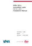
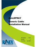
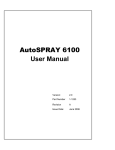
Case Patriot SPX
AutoSPRAY cable
(Part No. 1-2830)
Installation Manual
Part Number:
1-1285
Revision:
A
Issue Date:
October 2008
INTRODUCTION
The Case Patriot SPX AutoSPRAY Cable (Part No 1-2830) is designed to
suit the following installations:
Compatible Spray Controllers
Case Patriot SPX 3150
Case Patriot SPX 3200
Case Patriot SPX 4260
Case Patriot SPX 3185
The cable will control up to five individual boom sections; but does not
detect the status of the Master Switch in the installation.
Figure 1: AutoSPRAY Interface Cable (Part No 1-2830)
INSTALLATION
A schematic of the cable installation is shown in Figure 2
Figure 2: Schematic layout of typical AutoSPRAY installation
1-1285 Rev A
Case Patriot SPX AutoSPRAY Cable Installation
Page 1
It is recommended that all electrical wiring should be
installed by a qualified auto-electrician. Incorrect wiring may
damage the AutoSPRAY controller and/ or the spray rate
controller.
The installation and configuration of the RINEX AutoSPRAY controller is
detailed in the appropriate User Manual.
Step
Instruction
1.
Check that the spray controller and boom section switches are
functioning correctly before commencing the installation.
2.
Locate the control panel inside the cab with the rocker section
switches as shown below in Figure 3.
Figure 3 Case Patriot SPX section switch panel
1-1285 Rev A
Case Patriot SPX AutoSPRAY Cable Installation
Page 2
Step
3.
Instruction
Remove the screws holding the panel with the switches and lift
the panel to find the 6 pin connector, as shown below in Figure
4, with the section switches.
Figure 4 Case Patriot SPX section connectors
4.
Disconnect this 6 pin connector and ‘Tee’ in the Rinex 1-2830
cable between the 2 connectors. The supplied 1-2830 CASE
Patriot SPX AutoSPRAY interface cable simply connects in-line
between the two CASE connectors as illustrated in
5.
The other end of the cable with the round connector can be run
through the electrical panel and into to cab in the front corner of
the cab near the RINEX AutoSPRAY cable.
6.
Confirm that the spray controller and boom section switches
function correctly before connecting the cable to the RINEX
AutoSPRAY controller.
Check that all section switches function correctly and the
controller still displays the correct flow rate.
7.
Connect the 16 pin circular AMP connector on the other end of
the 1-2830 CASE Patriot SPX AutoSPRAY cable to the RINEX
AutoSPRAY controller.
8.
Confirm that the spray controller and boom section switches
function correctly.
1-1285 Rev A
Case Patriot SPX AutoSPRAY Cable Installation
Page 3
Step
Instruction
Note: If the RINEX AutoSPRAY controller is not connected directly to a
12Vdc source (vehicle power), then it is necessary to connect the
AutoSPRAY cable to the vehicle power supply for correct
operation of the system. Refer to APPENDIX A for connecting to
vehicle power.
1-1285 Rev A
Case Patriot SPX AutoSPRAY Cable Installation
Page 4
APPENDIX A
CONNECTING POWER
Power for the AutoSPRAY Controller /cable must be a clean
12Vdc source. Connecting the AutoSPRAY controller to
24Vdc will cause damage to the controller. If connecting to a
24Vdc vehicle, 12Vdc power must be connected to the same
power source the spray rate controller is using.
Step
1.
Instruction
Connect the RED wire, labelled POWER to a 12Vdc power source
that is controlled with the vehicle ignition wiring (power with the
vehicle is ON). Then connect the BLACK wire, labelled GROUND to
a ground point on the vehicle.
1-1285 Rev A
Case Patriot SPX AutoSPRAY Cable Installation
Page 5