1
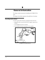
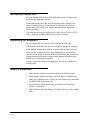
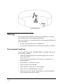
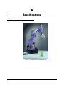
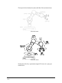
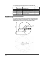
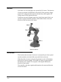
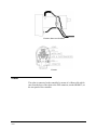
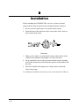
Download provided by eLABZ.com the information source for CNC, Robotics, Microcontroller and other electronics projects http://elabz.com/ 6&25%270(5#5X 5RERW#$UP User Manual Catalog #100361 Rev. A March 2002 2002 Intelitek Inc. SCORBOT-ER 2u Robot Arm User Manual Catalog #100361 Rev. A March 2002 Every effort has been made to make this book as complete and accurate as possible. However, no warranty of suitability, purpose or fitness is made or implied. Intelitek is not liable or responsible to any person or entity for loss or damage in connection with or stemming from the use of the software, hardware and/or the information contained in this publication. Intelitek bears no responsibility for errors that may appear in this publication and retains the right to make changes to the software, hardware and manual without prior notice. INTELITEK INC. 444 East Industrial Park Drive Manchester NH 03109-537 USA Tel: (603) 625-8600 Fax: (603) 625-2137 www.intelitek.com [email protected] Table of Contents 4#*HQHUDO#,QIRUPDWLRQ 111111111111111111111111111111111111111111111111111111111111111111111111111111 4 Handling Instructions .......................................................................................................... 1 Acceptance Inspection......................................................................................................... 2 Repacking for Shipment...................................................................................................... 2 Safety Precautions ............................................................................................................... 2 Warnings ............................................................................................................................. 3 Environmental Conditions ............................................................................................ 3 Robot Arm..................................................................................................................... 4 5#&RPSRQHQWV#DQG#6SHFLILFDWLRQV 11111111111111111111111111111111111111111111111111111111111 8 The Robot Arm.................................................................................................................... 5 Structure .............................................................................................................................. 6 Work Envelope.................................................................................................................... 8 Motors ................................................................................................................................. 9 Encoders .............................................................................................................................. 9 Cable.................................................................................................................................. 10 6#,QVWDOODWLRQ1111111111111111111111111111111111111111111111111111111111111111111111111111111111111111111 44 7#0DLQWHQDQFH 1111111111111111111111111111111111111111111111111111111111111111111111111111111111111111 45 Daily Operation ................................................................................................................. 12 Periodic Inspection ............................................................................................................ 13 Troubleshooting ................................................................................................................ 13 4 *HQHUDO#,QIRUPDWLRQ This chapter contains instructions for handling the SCORBOT-ER 2u robot. This chapter also includes important safety guidelines and warnings. Handling Instructions Lift and carry the robot arm only by grasping the body or the base. • Do not lift and/or carry the robot arm by its gripper, upper arm or forearm. • Do not handle the motors or encoders. • Do not handle the front or back panel of the controller. SCORBOT-ER 2u Mechanical Arm User Manual 0302 1 SCORBOT-ER 2u Mechanical Arm Acceptance Inspection Save the original packing materials and shipping carton. You may need them later for shipment or storage. After removing the robot arm from its shipping carton, examine it for signs of shipping damage. If any damage is evident, do not install or operate the system. Notify your freight carrier and begin appropriate claims procedures. The robot arm includes the gripper power cable 110Vac/220Vac, RS232 cable, 3 bolts for mounting robot and a set of hex wrenches. Repacking for Shipment Be sure all parts are back in place before packing the robot arm. The robot arm should be repacked in its original packaging for transport. If the original carton is not available, wrap the robot in plastic or heavy paper. Put the wrapped robot in a strong cardboard box at least 15 cm (about 6 inches) longer in all three dimensions than the robot. Fill the box equally around the unit with resilient packing material (shredded paper, bubble pack, expanded foam chunks). Seal the carton with sealing or strapping tape. Do not use cellophane or masking tape. Safety Precautions User Manual 0302 • Make sure the robot base is properly and securely bolted in place. • Make sure the robot arm has ample space in which to operate freely. • Make sure a guardrail, rope or safety screen has been set up around the SCORBOT-ER 2u operating area. • Do not enter the robot's safety range or touch the robot when the system is in operation. • Make sure loose hair and clothing is tied back when you work with the robot. 2 SCORBOT-ER 2u Mechanical Arm Robot Safety Range Warnings Be sure you heed the following warnings to prevent damage to the robot and controller and to ensure continued performance. Be sure you know how to immediately abort running programs and stop all robot movements: • If using a teach pendant, press the red Brake key. • Or, turn off the controller's power switch on the controller's rear panel. Environmental Conditions Do not install or operate the SCORBOT-ER 2u or controller under any of the following conditions: User Manual 0302 • Where the ambient temperature or humidity drops below or exceeds the specified limits. • Where exposed to large amounts of dust, dirt, salt, iron powder, or similar substances. • Where subject to vibrations or shocks. • Where exposed to direct sunlight. • Where subject to chemical, oil or water splashes. • Where corrosive or flammable gas is present. • Where the power line contains voltage spikes, or near any equipment which generates large electrical noises. 3 SCORBOT-ER 2u Mechanical Arm Robot Arm Do not abuse the robot arm: User Manual 0302 • Do not overload the robot arm. The payload may not exceed 600 grams (1.3 lb). It is recommended that the payload be grasped at its center of gravity. • Do not use physical force to move or stop any part of the robot arm. • Do not drive the robot arm into any object or physical obstacle. • Do not leave a loaded arm extended for more than a few minutes. • Do not leave any of the axes under mechanical strain for any length of time. Especially, do not leave the gripper grasping an object indefinitely. 4 SCORBOT-ER 2u Mechanical Arm 5 6SHFLILFDWLRQV The Robot Arm Figure 2-1: SCORBOT-ER 2u Mechanical Arm User Manual 0302 5 SCORBOT-ER 2u Mechanical Arm The following details the robot arm specifications: Mechanical Structure Vertically articulated Construction Enclosed Degrees of Freedom 5 rotational axes + gripper Payload Capacity 0.6 kg (1.3 lb) Axis Range Axis 1: Base rotation Axis 2: Shoulder rotation Axis 3: Elbow rotation Axis 4: Wrist pitch Axis 5: Wrist roll Operating Radius 320° +30° / -120° +80° / -107° +120°/ -120° 400° 517 mm (20.35") end of gripper Speed Definition (software) 10 settings Standard Gripper Electric, parallel fingers Gripper Opening 55 mm (2.16") Repeatability ±0.35 mm (0.014") Feedback Incremental optical encoders Homing Hard home on each axis Actuators 12Vdc servo motor on all axes Transmission Spur gears Weight 7.6 kg (16.7 lb) Structure The SCORBOT-ER 2u is a vertical articulated robot. It has five revolute joints: the base joint rotates the arm in a horizontal plane; the shoulder, elbow and wrist pitch joints rotate the robot's links in a vertical plane; and the wrist roll joint rotates the gripper. With gripper, the robot has six degrees of freedom. This design permits the end effector to be positioned and oriented arbitrarily within a large work space. User Manual 0302 6 SCORBOT-ER 2u Mechanical Arm The figures below identify the joints and links of the mechanical arm. Robot Arm Links Robot Arm Joints Each joint is driven by a permanent magnet DC motor via a spur gear transmission. User Manual 0302 7 SCORBOT-ER 2u Mechanical Arm The movements of the joints are described in the following table: Axis No. Joint Name Motion Motor No. 1 2 3 4 5 6 Base (Waist) Shoulder Elbow Wrist Pitch Wrist Roll Gripper Rotates the body. Raises and lowers the upper arm. Raises and lowers the forearm. Raises and lowers the gripper. Rotates the gripper. Opens and closes. 1 2 3 4 5 6 Work Envelope The length of the links and the degree of rotation of the joints determine the robot's work envelope. The figures below show the dimensions and reach of the robot, and a top view of the robot's work envelope. Operating Range: Side View Operating Range: Top View User Manual 0302 8 SCORBOT-ER 2u Mechanical Arm Motors The robot's five axes and gripper are operated by DC motors. The direction of motor revolution is determined by the polarity of the operating voltage: positive DC voltage turns the motor in one direction, while negative DC voltage turns it in the opposite direction. Each motor (except for gripper motor) has closed-loop control; that is, an encoder circuit provides the controller with feedback on the extent and direction of the movement of the motor. Robot Arm Motors Encoders The location and movement of each axis is measured by an electro-optical encoder attached to the shaft of the motor which drives the axis. When the robot axis moves, the encoder generates a series of alternating high and low electrical signals. The number of signals is proportional to the amount of axis motion. The sequence of the signals indicates the direction of movement. The controller reads these signals and determines the extent and direction of axis movement. User Manual 0302 9 SCORBOT-ER 2u Mechanical Arm Encoder, Motor and Gear Box Encoder Cable The robot is connected to the controller by means of a ribbon cable which runs from the base of the robot to the D50 connector, marked ROBOT, on the rear panel of the controller. User Manual 0302 10 SCORBOT-ER 2u Mechanical Arm 6 ,QVWDOODWLRQ Before installing the SCORBOT-ER 2u, be sure you have read and understood the safety instructions and warnings detailed in Chapter1. 1. Be sure you have ample space to set up the robotic system. 2. Fasten the base of the robot arm to the work surface with 3 bolts, as shown in the figure below. Robot Base 3. Make sure the robot is securely bolted in place. Otherwise the robot could become unbalanced and topple over while in motion. 4. Set up a guardrail, rope or safety screen around the robot's operating area for the mutual protection of both the operator and bystanders and the robot. 5. Place the controller and computer on a sturdy surface outside the robot's safety range. For additional installation instructions, refer to the Controller-USB user User Manual 0302 11 SCORBOT-ER 2u Mechanical Arm 7 0DLQWHQDQFH The maintenance and inspection procedures detailed below will ensure continued optimum performance of the robot arm. Daily Operation At the start of each working session, check the robot and controller, in the following order: 1. Before you power on the system, check the following items: „ The installation meets all safety standards. „ The robot is properly bolted to the work surface. „ All cables are properly and securely connected. Cable connector screws are fastened. „ No output is connected directly to a power supply. „ No people are within the robot's working range. 2. After you have switched on the controller, check the following items: „ The power LED on the controller light up. „ No unusual noises are heard. „ No unusual vibrations are observed in any of the robot axes. „ There are no obstacles in the robot's working range. 3. Bring the robot to a position near home, and activate the homing procedure. Check the following items: User Manual 0302 „ Robot movement is normal. „ No unusual noise is heard when robot arm moves. „ Robot reaches home position in every axis. 12 SCORBOT-ER 2u Mechanical Arm Periodic Inspection The following inspections should be performed regularly: 1. Visually check leads and cables. If any damage is evident, they must be replaced. 2. Check all bolts and screws in the robot arm using a wrench and screwdriver. Retighten as needed. Troubleshooting Whenever you encounter a malfunction, try to pinpoint its source by exchanging the suspected faulty component – for example, controller, arm, computer, cables with an identical component from a working system. Do not open the controller housing. There are no user-serviceable parts inside. Do not attempt repairs for which you are not qualified. Contact your agent or an authorized technician for repairs. The following provides guidelines for identifying and rectifying problems which you may encounter. Refer also the Controller-USB user manual for additional details. • • User Manual 0302 Controller functioning, but robot arm cannot be activated; or one axis fails to respond and Motor Error appears on screen. „ Make sure the Motors LED is lit. „ Make sure an obstacle is not blocking the robot. „ Make sure none of the axes has reached its mechanical limit. „ Make sure the robot cable is properly connected to ControllerUSB. „ Reinstall the USB driver. Refer to the section “USB Driver Installation” in the Controller-USB user manual. The gripper does not respond to open or close commands, or responds incorrectly. „ Make sure the robot cable is properly connected to the controller. „ Turn the controller off, then on again. „ If problem persists, contact your agent. 13 SCORBOT-ER 2u Mechanical Arm • • • User Manual 0302 Motor turns constantly in one direction, or responds incorrectly. „ Make sure the robot cable is properly connected to the controller. „ Turn the controller off, then on again. „ If problem persists, contact your agent. Errors in the accuracy of the robot „ Position deviations in one or more of the axes during the running of a program may be caused by a faulty encoder. „ Contact your agent. The Home position suddenly changes, and the robot continues operation in relation to the new Home. „ This fault may occur continually or occasionally, due to a noisy electrical system which disturbs the communication between the robot and the computer. „ Execute the Home routine, and reload the program you want to run. „ If the fault occurs frequently, use filtering equipment on your power line. „ If problem persists, contact your agent. 14 SCORBOT-ER 2u Mechanical Arm