1
Software Development to Control the Scorbot ER VII Robot With a
PC
ANTÓNIO FERROLHO
Electrical Engineering Department
Superior School of Technology of the Polytechnic Institute of Viseu
Campus Politécnico de Repeses, 3504-510 Viseu
PORTUGAL
MANUEL CRISÓSTOMO
Institute of Systems and Robotics
University of Coimbra
Polo II, 3030-290 Coimbra
PORTUGAL
Abstract: - The objective of the presented work was the development of a software package able to overcome
the limitations imposed by the actual Scorbot ER VII robot’s controller. The developed users friendly
“winATS” software runs in a windows platform such as 95, 98, NT, 2000 and XP. With the “winATS” it is
possible to develop robot’s programmes in C++, being these programmes executed at a PC level, not at
robot’s controller level. Nevertheless, the “winATS” also allow the development of programmes to be
executed at a robot’s controller level. Furthermore, it is also possible to have programmes running in the PC
and in the robot’s controller (mix solution), individually or simultaneously.
Key-Words: - Robot, parallel process, C++, control, serial RS232 protocol, application software.
1 Introduction
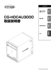
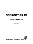
The Scorbot ER VII robot, shown in figure 1, is a
medium dimension robot manipulator, specially
designed to execution of manipulation tasks. It is
equipped with an electrical gripper, but, by using
another type of gripper, it is able to execute tasks
such as painting, grinding and welding. This robot
has 5 degrees of freedom, corresponding to 5
electrical joints [5].
Fig. 1 – Scorbot ER VII robot.
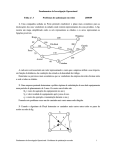
The Scorbot ER VII robotic system is composed
by the manipulator, a teach pendent, and the ATS
(Advanced Terminal Software) and ACL
(Advanced Control Language) software, as shown
in figure 2. Both ACL and ATS run under MS-DOS
[1], [3]. The ATS runs on-line with the robot. The
control is done directly from the PC to the
controller, though the serial RS232 port. It is
possible, for example, open and close the gripper,
do the robot’s homing, visualise and execute the
programmes resident in the memory, configure the
robot, etc [3].
The ACL works in a off-line mode, allowing the
development of programmes and its download to
the robot’s controller, though the serial RS232
connection [1] and [2]. The robot programme runs
in the robot’s controller, so that a robot programme
must be downloaded to the controller, before its
execution. Both ATS and ACL have several
limitations concerning programming and robot’s
control. Furthermore, they only run in MS-DOS
environment.
1
Scorbot ER VII
Program
Position
Speed
Trajectory
generator
Controller
The maker's software
(computer operating
under DOS):
- ATS
- ACL
θ1, ω1
Control axis 1
θ2, ω2
Control axis 2
θ3, ω3
Control axis 3
θ4, ω4
Control axis 4
θ5, ω5
Control axis 5
Fig. 3 – Robot’s axes controller.
Teach Pendant
Fig. 2 – The Scorbot ER VII robotic system.
The controller has a Motorola 68020 CPU and
128 Kbytes de RAM, so that the development of
more complex robot programmes is difficult.
Aiming the overcome of these limitations the
software “winATS” was developed. This users
friendly software runs in the windows 95, 98, NT,
2000 and XP environments. Furthermore, the users
programmes do not need to be in the robot’s
controller memory, once the programmes can be
run from the PC. It is possible to develop C++
robot’s programmes in the “winATS” and execute
them on the PC. Nevertheless, “winATS” also
allows the development of robot’s programmes to
be run from the robot’s controller. It is also possible
to have a hybrid solution, having programmes
running from the PC and others running from the
robot’s controller, either individually or
simultaneously. In this way, the reduced processing
power and memory of the controller are not an
obstacle to the development of more complex
robot’s programmes. In this way, the robot’s
controller can be freed to other tasks.
2 The Scorbot ER VII robot’s
controller
The controller of the Scorbot ER VII robot is a
multi-task system, allowing the execution of up to
20 simultaneous programmes. It has an interpreter
for the ACL language, developed by the robot’s
manufacturer [1] and [4].
The controller can control 8 axes, expansible up
to 11. Five of these 8 are used to control the robot’s
5 axis [4]. The others can be used to control
peripheral equipment, such as conveyer belts,
motors, etc. Figure 3 shows the axes controller
diagram.
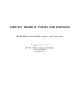
Position and velocity are calculated every 10 ms.
A PID (Proportional, Integral and Differential)
controller is used to control each axis. Each of these
PID controllers outputs a digital signal to input a
digital-analogue converter (DAC). This analogue
signal is then converted on a PWM (Pulse Width
Modulation) signal, with a frequency of 20 kHz and
an amplitude between -5 V e +5 V. A power drive
is further used to feed the electrical motors at ± 24
V DC [4]. Figure 4 shows the block diagram of the
controller for one axis.
Reference
Control of the
axis
(PID)
DAC
Analog Unit
PWM
Power Unit
DC motor
Encoder
Fig. 4 – Axis controller block diagram.
3 RS232 communication
RS232 protocol is used to communication between
the PC and the robot’s controller. The
communication is established trough the
transmission of ASCII (American Standard Code
for Information Interchange) code. ASCII code is a
7 bit code and a usually 8th bit, a parity bit, used as
a simple error detector.
In order to establish a bi-directional
communication between the PC and the robot’s
controller, it is necessary to configure several
parameters of the serial port, according to the table
1 [4].
Parameter
Baud rate
Stop bits
Handshake
Parity
Port
Data bits
Value
9600 bps
1
Software (Xon/Xoff)
None
COM1 or COM2
8
Table 1 – Configuration parameters.
2
4 Developed C++ functions and
classes
The graphical interface construction for this
application was developed in Borland C++ Builder.
Borland C++ Builder includes an extensive library
of re-used components and a RAD (Rapid
Application Development) tool environment. In the
low level development of the API (Application
Programming Interface) the Visual C++ was used
[6].
A thread process was created in order to poll the
serial port. An event is generated each time data is
presented in the serial port. In order to send data to
the robot’s controller, the message is placed in the
serial port queue. Asynchronous processing will be
used to send the message. For example, in order to
open the robot’s gripper, a data message is placed
in the thread queue and further sent to the robot’s
controller trough the RS232 channel. After the
delivery of the data, a waiting cycle is activated.
This cycle is waiting for the robot’s controller. It
ends when the robot’s controller sends back a
prompt (‘>’), a timeout error occurs or a
cancellation message is sent. Figure 5 shows the
messages cycle of the thread process.
MessageN
...
Message2
Message1
switch (Mensagem_Recebida){
case MSG_ESPERA:
ProcessamentoMensagemDeEspera();
break
case Mensagem1:
ProcessaMensagem1();
break;
case Mensagem2:
ProcessaMensagem2();
break;
...
case MensagemN:
ProcessaMensagemN();
break;
default:
if(Fila_De_Mensagens_Vazia){
ColocaNaFila(MSG_ESPERA);
}
}
Message processing
loop
Fig. 5 – Messages Cycle of the parallel process.
The main programme communicates with the
parallel process through the messages placed in the
waiting queue, being this queue managed by the
operating system. A message is immediately
processed as soon as it arrives at the parallel
process. In the case when there are no message in
the queue, the parallel process enters in a loop,
waiting for data from the robot’s controller. An
event is generated when data arrive.
The parallel process is activated in the beginning
of the communication with the controller. When the
communication with the robot’s controller is
finished, the resources allocated to the parallel
process are returned to the operating system.
Figure 6 shows the hierarchy structure of the
main classes of the developed API. The
Scorbot::BasicThread class is the lower level class
and the Scorbot::Controller class is the higher level
class.
class Controller
class Terminal
class BasicThread
Fig. 6 – Hierarchy structure of the API.
The Scorbot::BasicThread class is responsible to
deal with the parallel process management. The
Scorbot::Terminal class inherits all methods to
control parallel processes form the base
Scorbot::BasicThread class. This class works like a
terminal emulator and allows to gather text from
the RS232 channel. The Scorbot::Controller class
inherits all the functionalities from the
Scorbot::Terminal class. One of its tasks is sending
and receiving data for later analysis.
The developed API, for the “winATS”
application is based in thread process running
simultaneously with the main programme.
The ScorbotAPI library was developed having in
mind the access to the controller’s functions, as
shown in figure 7. This API allows us to
communicate with the robot’s controller.
PC
ScorbotAPI
Open(),Run(),SpeedA(),
Close(),OnMotorsOff(),
…
RS232
Controller
Scorbot ER VII
Fig. 7 –ScorbotAPI Library and the robot.
The available functions are divided in two
groups. The first contains the public methods and
3
Events
Public Methods
the second contains the methods representing
events. Table 2 shows some of these functions.
Function
Description
Changes the group A
SpeedA()
speed
Home()
Homing the robot
Switch off the robot’s
MotorsOff()
motors
Switch on the robot’s
MotorsOn()
motors
Close()
Closes the gripper
Open()
Opens the gripper
This event activates after
OnEndHoming()
homing
This event activates after
OnClose()
the execution of the
Close() function
This event activates after
OnOpen()
the execution of the
Open() function
This event activates after
OnMotorsOff() the motors are switched
off
This event activates after
OnMotorsOn() the motors are switched
on
Fig. 9 – winATS window.
In the left side of the “winATS” window it is
possible to see which programmes and points are in
the controller’s memory.
The reserved words, for the ACL language, are
automatically recognized and show up with a
different colour.
The help for a command is done double-clicking
in that command. Figure 10 shows the help
window.
Table 2 – Some available functions.
5 The developed software
After starting “winATS”, the communication
protocol must be established. Figure 8 shows the
window for that.
a)
b)
Fig. 10 – winATS Programme
a) Editing mode
b) Help window
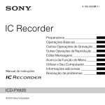
The window terminal console, shown in figure
11, simulates the ATS software. This window has
the ATS features and some new features which
were added.
Fig. 8 – Window for configuration of RS232
communication.
After the communication with the robot’s
controller is established, the “winATS” window as
in figure 9 shows up. This window has some
toolbars with a set of icons. These icons can be
used, for example, to switch the motors on and off,
to open and close the gripper, homing the robot, to
open and create files, etc.
Fig. 11 – Terminal console window.
4
Figure 12 shows the developed teach pendant.
This has multi-functions, such as, abort
programmes, move the robot, switch the motors on
and off, save robot’s locations, homing, etc.
setup button is used to do the configuration of the
axes 7 e 8.
a)
b)
Fig. 15 – Configuration system
a) Configuration window
b) Peripheral setup window
Other potentialities were developed in the
“winATS”, such as windows to edit, create, save
and modify robot’s locations, etc. An help, window
was also developed.
Fig. 12 – Teach pendant window.
The developed software allows us to visualize
the state of the external inputs and outputs, as
shown in figure 13.
6 Development of new projects for
the Scorbot ER VII robot
In this section the developed API, ScorbotAPI, will
be used to develop new projects. The Visual C++
(VCC) and the Borland C++ Builder (BCB) [6], [7]
will be used for that. The two presented projects
run at the PC level, not at the robot’s controller
level. These two simple examples show the way to
overcome the limitations of the original software.
6.1 Development of a new project using the
Visual C++
Fig. 13 – External inputs and outputs window.
The Task Manager window, shown in figure 14,
allows us to run, to abort, to erase, to suspend and
to resume programmes.
Table 3 shows the code that allows the robot to
execute a given path, in its work space. This code
shows that, using the developed ScorbotAPI,
controlling the robot is an easy task. To do that, the
communications must be configured, and then
sending robot’s commands to the robot’s controller.
#include <iostream>
#include <conio.h>
#include "./Scorbot/Scorbot.hpp"
using namespace std;
using namespace Scorbot;
int main (int argc, char* argv[]) {
Controller Robot;
Fig. 14 – Task Manager window.
Figure 15 shows the configuration window, used
to configure the robot’s controller. The Peripheral
// two robot’s work space points.
Struct Scorbot::Controller::Joint_t Coordinate_Point1 = {
8848,
-7375,
-15031,
-22476,
0
};
5
struct Scorbot::Controller::Joint_t Coordinate_Point2 = {
24867,
-15577,
28952,
16096,
7177
};
try {
// Communication port configuration.
Robot.Setup("COM1");
// Switches the RS232 channel on.
Robot.Connect();
// Defines two points in the controller’s memory.
Robot.DefinePosition("Pos1", Coordinate_Point1);
Robot.DefinePosition("Pos2", Coordinate_Point2);
// Swhitchs the motors on.
Robot.MotorsOn();
// Changes the robot’s speed to 30%.
Robot.SpeedA(30);
// Moves
for (unsigned int i = 0; i < 4; i++) {
Robot.Move("Pos1");
Robot.Move("Pos2");
}
Fig. 16 – Window for controlling the robot.
The code associated to the Outputs button, that
allow to test the 16 outputs of the controller, is
described bellow.
void __fastcall TFormMain::Button16Click(TObject
*Sender)
{
for (unsigned int i = 1; i <= 16; i++) {
Controller->SetOutput(i, true);
}
cout << "wait while the robot moves" << endl;
cout << "Press a key to finish the programme" << endl;
getch();
// Switches the RS232 channel off.
Robot.Disconnect();
}
catch(Scorbot::Exception& E) {
cerr << E.What() << endl;
}
return 0;
}
Table 3 – Example of developed code in VCC.
6.2 Development of a graphical application
using Borland C++ Builder
We use this example to develop the graphical
application presented in figure 16. After the
construction of the window and the inclusion of the
ScorbotAPI library in the BCB project, it is
necessary to include, in the main formulary, the
class responsible for the communication with the
robot’s controller.
for (unsigned int i = 1; i <= 16; i++) {
Controller->SetOutput(i, false);
}
}
In order to open or close the gripper, to do the
homing and to switch the motors on or off it must
be written the following code: “Controller>Open();”, “Controller->Close();”, “Controller>Home();”,
“Controller->MotorsOn();”,
“Controller->MotorsOff();”.
7 Scorbot ER VII robot control using
the Internet
Figure 17 shows the implementation of the control
of the Scorbot ER VII robot using the Internet. The
component “TServerSocket” which encapsulates
the windows API and deals with the TCP/IP
communications, was used.
The event “OnClientRead” was developed in
order to read and interpret the clients data. These
data in then transmitted to the robot trough the
ScorbotAPI.
6
Scorbot ER VII
RS232
SERVER
WinATS
ScorbotAPI
Controller
...
Internet
CUSTOMER 1
CUSTOMER 2
Internet
CUSTOMER n
Fig. 17 – Robot’s control through the Internet.
In order to control the robot from o client PC it
is necessary to activate the RS232 channel in the
“winATS”, and to give a value to the access port, as
shown in figure 18.
Fig. 18 – Window that allows to activate the RS232
channel.
The windows operating system’s client telnet
was used. It is necessary to choose, from the
desktop menu, “Start→Execute”, in order to
connect to the server, and then to write “telnet <IP
address of the server><port>”, as shown in figure
19.
VII robot’s controller level, be resident at the PC
level. In this way, it is possible to create
applications in the PC, easily and with the
versatility inherent to an open system, with a great
processing power, not possible at the robot’s
controller level. This work allows us to real-time
control the robot from a PC.
Some characteristics of the developed software,
“winATS”, are:
- the editor recognizes ACL language keywords, including comments and delimiters;
- downloads programmes to the controller’s
memory;
- easiness of editing programmes and locations;
- easiness of control of concurrent tasks in the
controller’s memory;
- easiness of set and visualise the state of the
outputs and visualise the inputs of the robot’s
controller;
- virtual Teach Pendant;
- the “winATS” also allows sending ACL
commands through RS232 port,
- execution of ACL basic commands through a
simple mouse click;
- online help, that recognizes the ACL keywords;
- easiness of saving location coordinates, either
in Cartesian or joint coordinates;
- Control of the Scorbot ER VII robot through
the Internet;
- allows the development of robot’s programmes
in Visual C++ and Borland C++ Builder;
- Etc.
References:
[1] "ACL–Advanced Control Language –
Reference Guide", Eshed Robotec, 4th
Edition, 1995.
[2] "ACLoff-line – User's Manual", Eshed
Robotec, 2nd Edition, 1995.
[3] “ATS–Advanced Terminal Software - Reference
Guide”, Eshed Robotec, 1st Edition, 1995.
Fig. 19 – Starting the TCP/IP connection.
After that it is possible to control the Scorbot ER
VII robot from a client PC.
8 Conclusões
The developed software, “winATS”, allows to the
command instructions, existing at the Scorbot ER
[4] "Scorbot ER VII, User's Manual", Eshed
Robotec, 2nd Edition, 1996.
[5] Moshe Shoham, Textbook 1, Fundamentals of
Robotics, Eshed Robotec, 1984.
[6] David J. Kruglinski, Visual C++, Microsoft
Press, 1997.
[7] William P. Alves, C++ Builder 6, Erica,
2002.
The authors wish to thank to their students, Mr.
Nuno Manuel A. Loureiro and Mr. Henrique
Manuel C. Cardoso for their valuable contribute in
the development of this project.
7