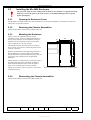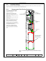
1
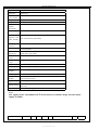
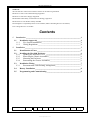
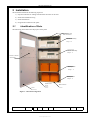
http:/www.alarmhelp.net
Technical Data
Sheet
ADVANCED ELECTRONICS LTD
Installation Manual
Mx-4800
Fire Alarm Control Panel
Document Reference
680-038
Rev
01
Author
AB
www.ukpanels.com
RFM4800
Page
1 of 8
http:/www.alarmhelp.net
Mx-4800
Enclosure
Steel IP 30
Dimensions H
x W x D mm
950 x 450 x 188
Weight
23Kg
Temperature
0°to 45°C
Cable Entries
(20mm
knockouts)
36 x top, 9 x top rear and 2 x bottom
Mains Supply
220 –240V, 47 –63 Hz AC, 0.7A
Battery
Capacity (For
24Hr. standby)
24V 4Ah Internal (minimum)
Charging
Current
2x 2.2A Temperature Compensated
Power Supply
2x Separate 24V DC, 5A Universal Input
Switched Mode
200
(1000 when networked)
Number of
Fire Zones
24V 38Ah Internal (maximum)
Number of
Loops
2 to 8
Devices per
Loop
As per Detector Manufacturer’s Specifications
Loop Current
500mA max. per Loop
Protocols
Apollo: S90, XP95, Discovery, Explorer & Hochiki ESP
Sounder
Outputs
8 x 1A Programmable
Relay Outputs
4 x 1A 30V AC/DC (max)
Open Collector
Outputs
4 x Programmable
Digital Outputs
12 x Programmable
Auxiliary
Supply Output
2x 24V DC, 300mA
Event Log
1000 Event & Diagnostic + 500 Fire
10mA. 5V (min) Programmable
10mA 30V DC (max)
See notes
Notes
Aux supply tracks a maximum of 0.5V below battery terminal voltage when no mains
supply available.
Document Reference
680-038
Rev
01
Author
AB
www.ukpanels.com
RFM4800
Page
2 of 8
http:/www.alarmhelp.net
Standards:
The Mx-4800 Fire Alarm Control Panel conforms to the following standards:
BS EN54-2: 1998 Control and Indicating Equipment
BS EN54-4: 1998 Power Supply Equipment
BS EN60950: 2000 Safety of information technology equipment
BS EN50130-4: 1996 Product Family Standard
Electromagnetic Compatibility Directive 89/336/EEC (and the amending directive 92/23/EEC)
Low Voltage Directive 73/23/EEC
Contents
1
Introduction ____________________________________________________________4
1.1
Installation Approvals________________________________________________4
1.1.1
Fire System Installations ___________________________________________4
1.1.2
Wiring Regulations _______________________________________________4
2
Installation _____________________________________________________________5
2.1
Identification of Parts ________________________________________________5
2.2
Installing the Mx-4800 Enclosure ______________________________________6
2.2.1
Opening the Enclosure Cover _______________________________________6
2.2.2
Removing the Chassis Assemblies ___________________________________6
2.2.3
Mounting the Enclosure ___________________________________________6
2.2.4
Remounting the Chassis Assemblies__________________________________6
2.3
Installation Wiring __________________________________________________7
2.3.1
Recommended Cable Routing Arrangement____________________________7
2.4
Battery Installation __________________________________________________8
2.5
Programming and Commissioning _____________________________________8
Document Reference
680-038
Rev
01
Author
AB
www.ukpanels.com
RFM4800
Page
3 of 8
http:/www.alarmhelp.net
Cautions and Warnings
STOP
BEFORE INSTALLATION – Refer To the Ratings shown on the label inside the product and
to the ‘Specifications Chart’ in this document.
Please read this manual carefully. If you are unclear on any point, DO NOT proceed. Contact
the manufacturer or supplier for clarification and guidance.
Only Trained service personnel should undertake the Installation, Programming and
Maintenance of this equipment.
This product has been designed to comply with the requirements of the Low Voltage Safety
and the EMC Directives. Failure to follow the installation instructions may compromise its
adherence to these standards.
This equipment is constructed with static sensitive components. Observe anti-static
precautions at all times when handling printed circuit boards. Wear an anti-static earth
strap connected to panel enclosure earth point. Before installing or removing any printed
circuit boards remove all sources of power (mains and battery).
1 Introduction
This manual covers the installation, programming and commissioning of the Mx-4800 Fire Alarm Control Panel.
Refer to the User Manual (Document No. 680-015) and to the Installation / Commissioning Manual (Document
No. 680-014) for details of how to operate the panel and for general installation / commissioning instructions for
the Mx-4x00 range of panels.
The Mx-4800 Large Enclosure Panel is a Multiple Loop, Analogue Addressable Fire Alarm Control
Panel with provision for up to eight loops.
The panel is designed for use with the Apollo Discovery, Explorer, XP95 and Series 90 and Hochiki ESP fire
detection devices.
Install the panel, detection loops, sounder circuits, etc. in accordance with the instructions in Section 2 of this
manual and in Section 2 of Manual 680-014. Then program the operation in accordance with the instructions
detailed in Section 3 of Manual 680-014.
1.1
1.1.1
Installation Approvals
Fire System Installations
The panel must be installed and configured for operation in accordance with these instructions and the applicable
fire systems installation regulations appropriate to the country and location of the installation.
1.1.2
Wiring Regulations
The panel and system must be installed in accordance with these instructions and the applicable wiring codes and
regulations appropriate to the country and location of the installation.
In the UK, the installation must comply with the requirements of the IEE Wiring Regulations – Sixteenth Edition
or later.
Document Reference
680-038
Rev
01
Author
AB
www.ukpanels.com
RFM4800
Page
4 of 8
http:/www.alarmhelp.net
2 Installation
The should be installed in the following sequence:
1) Prepare knockouts for cabling and install the enclosure on the wall
2) Install the installation wiring
3) Install the batteries
4) Program and commission the panel
2.1
Identification of Parts
The following picture shows the major parts of the panel.
Bus-bars for cable
earth connections
Chassis Assembly
Loops 1 - 4
Chassis Assembly
Loops 5 - 8
Plate for switches /
Zone LED's
Battery Shelf
Loops 1 - 4
Battery Shelf
Loops 5 - 8
Earth Lead to
Cover
Rear Enclosure
Door
Figure 1 - Internal Arrangement
Document Reference
680-038
Rev
01
Author
AB
www.ukpanels.com
RFM4800
Page
5 of 8
http:/www.alarmhelp.net
2.2
Installing the Mx-4800 Enclosure
The panel can weigh in excess of 80kg when the batteries are installed. Use appropriate fixing
hardware to secure the panel to the wall. Observe recommended lifting practices to guard
against spinal injury.
2.2.1
Opening the Enclosure Cover
The Mx4800 is provided with two key-lock assemblies for securing the hinged door to the backbox. Insert and
turn the key to open the enclosure.
2.2.2
Removing the Chassis Assemblies
Follow the procedures / instructions in Manual 680-014.
Mounting the Enclosure
Firstly, remove the required knockouts for the
installation wiring. There are sufficient knockouts on
the top of the enclosure for all installation wiring. In
addition, there are knockouts at the top of the back
wall, if required, for rear entry cabling.
35
450
380
20
2.2.3
515
The diagram opposite shows the positions of the six
holes. Use all six positions to ensure the panel is held
securely to the wall.
370
950
Drill the required holes in the supporting wall using a
drill bit diameter 10.0 mm and plug with a suitable
50mm (minimum) long metal expansion plug. Affix the
panel to the wall with M6 screws (length 50mm
minimum).
Ensure that there is sufficient space to allow the door to
be opened when the panel is mounted. In addition,
there should be sufficient space below the panel to
allow access to the RS232 connected, if fitted.
Finally, use a brush to remove any dust or swarf from
inside the enclosure.
2.2.4
Figure 2 - Enclosure Size and Fixing Point Dimensions
Remounting the Chassis Assemblies
Follow the procedures / instructions in Manual 680-014.
Document Reference
680-038
Rev
01
Author
AB
www.ukpanels.com
RFM4800
Page
6 of 8
http:/www.alarmhelp.net
2.3
Installation Wiring
For further information on Recommended Cables and how to install the AC Mains, loop, sounder, relay and AUX
outputs circuits refer to the relevant sections in Manual 680-014.
2.3.1
Recommended Cable Routing Arrangement
It is recommended that the routing
arrangement shown in the diagram
opposite be employed.
Segregate the low voltage wiring
(Loop Circuit, Sounder Circuits,
RS485 and AUX Supply) from the AC
Mains Wiring.
Use rear knockout rows
for lower chassis cables
Use front knockout rows
for upper chassis cables
Segregate any wiring connected to the
relay contacts.
Eyelets are provided in the rear of the
backbox to enable the cables to be
securely fastened using tie-wraps.
Field Installation
Wiring
Sounders and AUX wiring should be
routed behind the chassis assembly and
tie-wrapped to the backbox.
Cable screens / shields should be
connected to the backbox using the
bus-bars provided near the knockout
holes.
Battery Wiring
Route cables through hole
in upper battery shelf –
Ensure that the hole is
protected by a grommet.
Figure 3 - Internal arrangement showing recommended routing of
cables.
Document Reference
680-038
Rev
01
Author
AB
www.ukpanels.com
RFM4800
Page
7 of 8
http:/www.alarmhelp.net
2.4
Battery Installation
The panel contains two shelves on which to place the batteries. Refer to Figure 1 and Figure 3 for their location.
Ensure that the battery cables for the lower shelf are routed through the hole in the upper
battery shelf and that a suitable grommet (minimum flame retardent rating of 94HB) is used
to protect the cable from damage.
Refer to the Specifications chart for minimum and maximum battery sizes permitted. Refer to Manual 680-014 for
further information on battery wiring and Battery Standby Calculations.
2.5
Programming and Commissioning
The Mx-4800 programming is identical to the other panels in the Mx-4000 range. Refer to Manual 680-014 for
further information.
Document Reference
680-038
Rev
01
Author
AB
www.ukpanels.com
RFM4800
Page
8 of 8