1
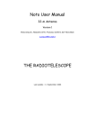
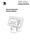
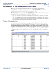
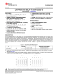
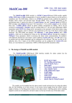
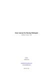
WIDE RANGE s.r.l. Via Galileo Ferraris 21, 20090 Cusago (MI) Tel. 02-9019366 Fax. 02-9019267 E-mail : [email protected] Web: www.widerange.it P. IVA IT 11220980152 User manual for controller WRPICO SW Version F16 File:Man_alip16_UK.docx Pag 1 di 15 09/01/13 SUMMARY USER MENU .......................................................................................... 5 SPEED:.................................................................................... 5 PITCH OFF: ............................................................................. 5 PITCH OFF 2: .......................................................................... 5 DELAY:.................................................................................... 6 DELAY1-2 ................................................................................ 6 COUNTER: .............................................................................. 6 LABELs QUEUE: .................................................................... 7 CONFIGURATION MENU ...................................................................... 8 AIR ASSIST TIME (PISTON): .................................................. 8 PRINT TIME:............................................................................ 8 AIR ASSIST DELAY (PISTON): .............................................. 8 START RAMP: ........................................................................ 9 STOP RAMP:........................................................................... 9 TOTAL COUNTER : ................................................................ 9 NUMBER OF LABEL FOR EACH PRODUCT: ..................... 10 INPUTS CN2 ........................................................................................ 11 OUTPUTS CN1 .................................................................................... 11 RELE CN5............................................................................................ 11 POWER SUPPLY CN4......................................................................... 11 FUNCTIONS OF WRPICO CONTROLLER ......................................... 12 1 LABEL MODE .................................................................... 12 2 LABELS MODE .................................................................. 12 MECHANICAL RATIOS ......................................................... 13 AUTOMATIC RECOVERY OF MISSING LABELs: ............... 13 NEAR END OF ROLL: ........................................................... 14 RAMPS: ................................................................................. 14 JOG MODE: .......................................................................... 14 ERRORS................................................................................ 14 BOARD LAYOUT................................................................................. 15 File:Man_alip16_UK.docx Pag 2 di 15 09/01/13 The following drawing shows the front panel: DISPLAY LED 4 CIFRE C B A Speed Pitch Off Delay Time On Off It comprises a 4 digit display with 4 Led on the left side, indicating the various function, and a keyboard of 3 keys with the following meaning : A B C Enter Plus (+) Minus (-) It is possible to shows the operating parameters of the labeller by mean of the 4 digit dispaly, and it is possible to modify their value with the keyboard. After power-on, it wil be shown the software version for about 2 seconds. As it is possibile to manage 1 or 2 label on the same product, the display shows the actual setup: 1 L 2 L supply of 1 Label supply of 2 Label on the same product (1 Label mode) (2 Label mode) The operating parameters are split in 2 menus: USER and CONFIGURATION. On power-on, the user menu parameters are shown. File:Man_alip16_UK.docx Pag 3 di 15 09/01/13 Parameters in the user menu are the following: *1 *2 SPEED PITCH OFF PITCH OFF 2 DELAY DELAY1-2 PRODUCT COUNTER LABELS QUEUE in m/min in mm in mm in Sec in Sec number number *1 (Delay1-2 is present in this menu only in the 2 Label mode) *2 (Label queue is present in this menu only in the 1 Label mode) The configuration parameters are the following: AIR ASSIST TIME (PISTON) PRINT TIME AIR ASSIST DELAY (PISTON) START RAMP STOP RAMP TOTAL COUNTER LABEL NUMBER in Sec in Sec in Sec in steps in steps number number 1 or 2 All the parameters of both menus, are held in memory when the equipment is switched off. With the Enter key, is possibile to shift in sequence all the parameters, showing and modifing their value in both menus. To acces the configuration menu, is necessary to switch-on the equipment holding down the Plus and Minus keys. Entering the configuration menu, it is shown on the display the word Set. To come back to the user menu it is necessary to switch-off and switch-on again the equipment. (All the parameters modified are held in memory). It is possible to modify the value of a parameter, showing it on the display pushing the Enter key, and by means of the Plus and Minus keys, is possible to set the needed value. File:Man_alip16_UK.docx Pag 4 di 15 09/01/13 USER MENU SPEED: Speed of the product in m/min. This parameter is indicated by the first upper Led on, while the other 3 are off. It is possible to modify the value with the Plus and Minus keys. The allowed values for this parameter are comprised from 1 to 99.9 m/min PITCH OFF: Distance from the starting edge of a label and the stop photocellule in mm. This parameter is indicated by the second Led on, while the other 3 are off. It is possible to modify the value with the Plus and Minus keys. The maximum value is 999.9 mm. PITCH OFF 2: This parameter is shown in 2 Label mode only. Distance from the starting edge of the second label and the stop photocellule in mm. This parameter is indicated by the second Led on, while the other 3 are off. It is possible to modify the value with the Plus and Minus keys. The maximum value is 999.9 mm. File:Man_alip16_UK.docx Pag 5 di 15 09/01/13 DELAY: Delay from the detect time of the product, to the beginning of supply the first label, in Sec. This parameter is indicated by the third Led on, while the other 3 are off. It is possible to modify the value with the Plus and Minus keys. The maximum value is 9.99 Sec. DELAY1-2 This parameter is shown in 2 Label mode only. Delay from the end of supply the first label on the product and the beginning of supply the second label on the same product, in Sec. This parameter infleunce the position of the second label relative to the first one. This parameter is indicated by the second and third Led on, while the other 2 are off. It is possible to modify the value with the Plus and Minus keys. The maximum value is 9.99 Sec. COUNTER: Counter of the labelled product. This parameter is indicated by the fourth Led on, while the other 3 are off. It is possible to modify the value with the Plus and Minus keys. The maximum value is 9999 Sec. The value is incremented automatically each time a product is labelled. File:Man_alip16_UK.docx Pag 6 di 15 09/01/13 LABELs QUEUE: Number of labels in the queue between the stop photocellule and the peeling bar. This parameter is indicated by all the 4 Led off. It is possible to modify the value with the Plus and Minus keys. This value is used during the recovery of the missing labels and the maximum value is 30 plus 2 additional possible values “d” and “E”. When the value is set to “d”, the label recovery is disabled, and in case of a missing label, the system doesn’t show any error and continue to work properly. When the value is set to “E”, the label recovery is disabled, and in case of a missing label, the system fall in error that is shown on the display. This parameter is shown only in 1 Label mode because in 2 Label mode the missing label is not managed File:Man_alip16_UK.docx Pag 7 di 15 09/01/13 CONFIGURATION MENU It is possibile to enter the configuration menu’, holding down both Plus and Minus keys during switch on. AIR ASSIST TIME (PISTON): AIRASS output is activated for this time starting from the end of the ASSIST DELAY time. This parameter is indicated by the firs upper led on, while the other 3 are off. It is possible to modify the value with the Plus and Minus keys. The maximum value is 9.99 Sec. PRINT TIME: PRINTER output is activated for this time, after each label is applied The parameter is indicated by the second led off, while the other 3 are on. It is possible to modify the value with the Plus and Minus keys. The maximum value is 9.99 Sec. AIR ASSIST DELAY (PISTON): It sets the delay between starting of label supply and activation of AIRASS output. The parameter is indicated by the upper two leds off, while the lower ones are on. It is possible to modify the value with the Plus and Minus keys. The maximum value is 9.99 Sec. File:Man_alip16_UK.docx Pag 8 di 15 09/01/13 START RAMP: Number of step while the speed of the supplied label vary from 0 to the steady state value set with the parameter SPEED. This parameter is indicated by the third led off while the other 3 are on. It is possible to modify the value with the Plus and Minus keys. The maximum value is 255 steps. The ramp take place only if the speed is greater than 10 m/min and the number of START RAMP steps and STOP RAMP steps are not equal zero. STOP RAMP: Number of steps while the speed of the supplied label vary from the steady state value set with the parameter SPEED, to the rest condition. This parameter is indicated by the fourth led off while the upper 3 are on. It is possible to modify the value with the Plus and Minus keys. The maximum value is 255 steps. The ramp take place only if the speed is greater than 10 m/min and the number of START RAMP steps and STOP RAMP steps are not equal zero. TOTAL COUNTER : This parameter shows the total number of labelled product during the entire life of the machine. This parameter is indicated by the four led off. When it is reached the number 9999, the display goes back to 0 and is light-on the first decimal point to the right that represents an increment of 10000, the second decimal point represents an icrement of 20000 and so on. It is possible to reset to 0 the counter pushing both the Plus and Minus keys. File:Man_alip16_UK.docx Pag 9 di 15 09/01/13 NUMBER OF LABEL FOR EACH PRODUCT: It shows the number of label applied on each product. This parameter is indicated by all four leds off and by the digits 1 L or 2 L as shown in figure. It is possible to switch from 1 to 2 label and vice versa holding the Plus and Minus keys. File:Man_alip16_UK.docx Pag 10 di 15 09/01/13 INPUTS CN2 IN0 IN1 IN2 IN3 IN4 IN5 IN6 IN7 V24 V24 GND GND Pin1 Pin2 Pin3 Pin4 Pin5 Pin6 Pin7 Pin8 Pin9 Pin10 Pin11 Pin12 FSTART FSTOP FINBOB Product Start Photocell Label Stop Photocell Near End of Roll FAULT 24Vcc 24Vcc GND GND Stepper Driver Fault Power supply 24Vdc for photocells Power supply 24Vdc for photocells Common reference at 0V Common reference at 0V OUTPUTS CN1 OUT0 OUT1 OUT2 OUT3 OUT4 OUT5 OUT6 OUT7 VPOW GND Pin1 Pin2 Pin3 Pin4 Pin5 Pin6 Pin7 Pin8 Pin9 Pin10 CKSTEP PRINT ALLQFB ASSIST Stepper driver Clock Marker Near end of roll Alarm Active during label supply ALARM VPOW GND Alarm out Power supply for electovalves and relays Common reference at 0V RELE CN5 Pin1 Pin2 Pin3 COM NC NO Comune rele ALLARME Normalmente Chiuso rele ALLARME Normalmente Aperto rele ALLARME POWER SUPPLY CN4 Pin1 Pin2 Pin3 Pin 4 8Vac 8Vac 24Vac 24Vac Power Supply input 8Vac Power Supply input 8Vac Power Supply input 24Vac Power Supply input 24Vac File:Man_alip16_UK.docx Pag 11 di 15 09/01/13 FUNCTIONS OF WRPICO CONTROLLER 1 LABEL MODE The equipment is waiting for the start signal when the product pass in front of the photocellule. When the start signal is detected, the ASSIST out is activated for the time indicated by the value ASSIST TIME. At the same time starts counting the delay time, and at the end of the delay, one label is supplied. Varing the DELAY value is possible to change the position of the labels on the product. At the end of the supply phase it is enabled the PRINT out for the PRINT TIME parameter. At the end of this time, the PRINT out is disabled, and the machine is waiting for a new product. The function of PITCH-OFF parameter is to align the edge of the label with the peeling bar. For the position of the stop photocellule, the only requrement is that the maximum number of the label queue between the stop photocellule and the peeling bar, is 32. 2 LABELS MODE The equipment is waiting for the start signal when the product pass in front of the photocellule. When the start signal is detected, the ASSIST out is activated for the time indicated by the value ASSIST TIME. At the same time starts counting the delay time, and at the end of the delay, othe first label is supplied. Varing the DELAY value is possible to change the position of the first label on the product. At the end of supply of the firs label, starts counting the delay time (DELAY 1-2) between the first and the second label, and at the end of this time start supply of the second label. Varing the DELAY 1-2 value is possible to change the position of the second label relatively to the first one. For the position of the stop photocellule, the requrement is that under the stop photocellule there should be a label of the same type that is present on the peeling bar (the first label). See the figure below, where shadowed, are shown the positions allowed for the stop photocell. Direction of products Peeling Bar File:Man_alip16_UK.docx Pag 12 di 15 09/01/13 MECHANICAL RATIOS The system is designed to have a mechanical ratios of the label conveying system of 0.35 mm/step. Under this condition the speed and pitch off are correct. If the mechanical ratios are different, the system continue to work but the the value indicated on the display are not real. To calculate the mechanical ratio of the label conveying system in mm/step must be used the following formula: Reti where Dr 3,14 Zm Zr 400 Dr Zm Zr diameter of the label conveying roll in mm teeth number of the motor gear teeth number of the roll gear As an example: Reti Dr = 45mm Zm = 20 Zr = 20 45 3,14 20 0,35 20 400 AUTOMATIC RECOVERY OF MISSING LABELs: This function is on, only in the case of a single label is applyed on the product. After switch on, the first and the second label applied on the first and second product, are used to internally calculate in an automatic mode the lenght of the label. This lenght is used to stop the motor if a label is missing on the roll and the stop signal is not generated. After the missing label has reached the peeling bar position, there is one more automatic supply of a label (the missing label), to pass the blank position, and to be ready with a new label on the peeling bar to be applied on the next product. For this function to operate correctly, it must be set correctly the parameter LABEL QUEUE. If 2 consecutive missing labels are detected, there is an ERROR indicating break of roll (E 2 on the display). It is possible to reset this state by means of the Enter key. File:Man_alip16_UK.docx Pag 13 di 15 09/01/13 NEAR END OF ROLL: when the input FBOB is short to GND by the near end of roll photocellule, there is the normal supply of labels (the roll is far from end). When this input is opened, the ALLQFB out is activated. At this point the machine continue to apply labels with an autonomy of about 2 m. When this lenght ends, there is an ERROR indicating end of roll with E 1 shown on the display and the ALARM RELAY is enabled. It is possible to reset this state, changing the roll of labels and pushing the Enter key. RAMPS: If a SPEED greater than 10 m/sec is necessary to set properly the values for START and STOP RAMP in the configuration menus. These values may vary depending on the type of motor, mechanical gears used and the type of label used. A good choice for theese parameters is found sperimentally, taking care to use the minimum value of step ramp that yelds good results when labelling. Usually the start ramp needs a number of steps greater than the stop ramp. JOG MODE: Holding down the Enter key for 5 Sec it is possible to enter the JOG mode, where it is possible to supply a label by means of the Plus key. In this mode the start photocellule is ignored; it is possible to return to the normal mode holding down the Enter key for 5 Sec again. ERRORS When an error condition is displayed, the possibile causes are the following: E1: End of Roll. The rolli is ended. Input FINBOB is disconnected from GND. E2: Break of roll/Missing labels. The STOP photocell didn’t send the signal of label detected. E5: Fault Stepper Motor Driver. The stepper motor driver is in fault condition. See the manual of the stepper motor driver. In error condition the system is disabled an not in condition to operate. The user must remove physically the error condition, and then press the ENTER key to reset the control board. File:Man_alip16_UK.docx Pag 14 di 15 09/01/13 BOARD LAYOUT File:Man_alip16_UK.docx Pag 15 di 15 09/01/13