1
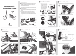
3 Mount Positioning
3 Mount Positioning
6 Roller Form-up Check and Motor Fix
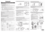
When motor, roller and tires are located in a straight line, utmost power is passed.
Thus, it’s important t
tor mount using guide roller.
8 Electronic Controller Installation
Decelerator limit setting
Electronic controller installation
Tire
Tighten the limit setting bolt slowly until
the decelerator drops downward at certain
point.
If the decelerator doesn’t go down when
you tighten a bolt to the end, use spring
after cutting.
Six-angle wrench
Limit setting bolt
Maximum
friction position
1. Attach the Electronic controller at seat tube
tightly using the velcro tape.
2. Connect middle motor cable and middle
controller cable . And connect red motor
cable and red controller cable . And then,
Connect the remaining cables .
3. Cover the cables with the corrugated tube.
Guide roller
Distance between
tire and guide roller : 1~2mm
Motor cable
Decelerator
3
2
1
Electronic
controller
cable
Velcro tape
too far
Find installation point by
moving up and down motor mount
Corrugated
tube for
cable
arrangement
too close
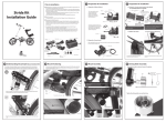
7 Motor cap assembly
Roller form-up check
Accelerator Installation
rubber ring
Put the cable tie(long ones) as shown in the picture.
Install the accelerator onto the right handle grip.
Guide roller
Turning radius
of decelerator
Accelerator
Motor mount
Cable tie
Tire
Similar angle to brake lever angle
Check if they are
installed in
straight line.
Six-angle wrench
Guide roller
el
ar
f re
Ce
ro
nte
e
wh
Accelerator
If the guide roller is not aligned with the tire, loosen
the mount cover a little. And then adjust the angle
and tighten it again as refer to the picture above.
Install motor mount using rubber ring.
Motor cap
-5-
4 Driving Roller Assembly
-6-
Assembly
-9-
9 PAS sensor Installation Guide (PAS only)
5 Motor Installation
Motor
Place it to control
with r
Motor decelerator set
- 10 -
9 PAS sensor Installation Guide (PAS only)
Magnet disk installation
Sensor installation
Six-angle wrench
Motor
Spring
Washer
Roller
Check for the right
side of the roller
Roller lock ring
cover for installation
Bolt
Roller
?
ring
Push the motor decelerator set
decelerator in the direction of
the arrow and put the motorring into the opposite
side of motor decelerator set.
Hold the roller up with hand.
ring
Turn the motor
about 45 degrees to make
spring tense.
Fix the two spr
with six-angle wrench. (in the
order of 1-2-3-4)
※ If the bolts are too tightened, it may damage the motor.
Bend the motor cable 90
degrees as shown with arrow
mark in the picture.
?
Space block(3mm)
C
necessary
Space block(2mm)
Sensor
Double-sided tape
Both directions are possible
If use two space blocks
(2mm + 3mm)
?
Magnet disc
Bolt 2x5
Distance between
sensor and magnet disc:
install closer than 5mm
6 Roller Form-up Check and Motor Fix
Roller lock ring
Use space block to make gap closer than 5mm
between sensor and magnet.
Bolt 2x8
Sensor
The sensor's arrow mark
is facing the magnet.
Decelerator limit setting
Sensor
Motor mount
Six-angle wrench
Limit setting bolt
Magnet disk
Motor decelerator set
Diameter Ø 16mm
Pedal rotate
direction
(painted
arrow)
Diameter Ø 22mm
Diameter Ø 30mm
C
cessary
Sensor
cable direction
Distance between
sensor and magnet disc:
install closer than 5mm
Lift up the decelerator to the maximum point
-7-
-8-
- 11 -
- 12 -