1
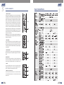
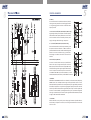
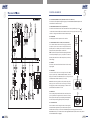
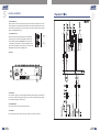
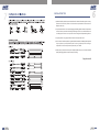
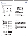
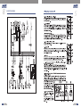
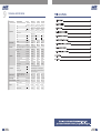
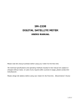
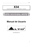
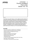
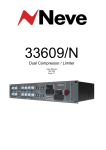
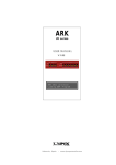
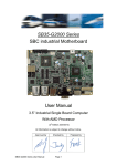
MX SERIES MIXER
The mains plug or an appliance coupler is used as
the disconnect device, the disconnect device shall
remain readily operable.
2
TABLE OF CONTENTS
1. INTRODUCTION..................................................................................4
2. FEATURES..........................................................................................4
3. USEFUL DATA......................................................................................4
4. HOOKUP DIAGRAM.............................................................................5
4. CONTROL ELEMENTS.........................................................................6
5. INSTALLATION TIPS ..........................................................................11
6. WIRE CONNECTIONS...... .................................................................12
7. BLOCK DIAGRAM ..............................................................................13
8. TECHNICAL SPECIFICATION.............................................................17
9. GUARANTEE ....................................................................................19
3
INTRODUCTION
Thank you for purchasing the MX series mixing console. This series include several mixers
(MX.5 V2,MX.6/USB V2, MX.10/USB V2, MX.12/USB V2).
There is 2-band EQ on all mono channels (MX.5 V2), and 3-band EQ on mono channels,
stereo channels (MX.6/USB V2, MX.10/USB V2, MX.12/USB V2), and built-in stereo USB V2/
Audio interface(MX.6USB V2, MX.10USB V2, MX.12USB V2). These mixers are really ideal for
small club gigs.
Please read this manual carefully so you can take advantages of all the features of the MX series.
Thank you again for making the right choice in purchasing the TOPP PRO MUSIC GEAR.
FEATURES
MX.5 V2
1 mono inputs with gold plated XLR and Balanced TRS jack
2 stereo inputs with Balanced TRS jack
2-band EQ on all mono channels
2-Track IN/OUT
Balanced XLR & TRS jack output
MX.6/USB V2, MX.10/USB V2, MX.12/USB V2
2 mono inputs (4 for MX.12/USB V2) with gold plated XLR and Balanced TRS jack
4 (2 for MX.6/USB V2) stereo inputs with Balanced TRS jack
GAIN control and +48V phantom power for mono inputs
3-band EQ on all mono channels and stereo channels
plus 75Hz low cut filter on all mono channels (For MX.10/USB V2 & MX.12/USB V2)
1 POST-fader AUX send for effect sends can be changed in PRE-fader for monitoring
Peak LED in each channel
2-Track IN/OUT with discrete switches for routing to Control Room and to Main Mix
Built-in stereo USB V2/Audio interface(For MX.6USB V2, MX.10USB V2, MX.12USB V2)
USEFUL DATA
Please write your serial number here for future reference.
Serial Number:
Data of Purchase:
Purchased at:
4
HOOKUP DIAGRAM
Small Club Gig
Microphones 1 and 2
Mono in/Stereo out Reverb
Drum Machine
Headphones
Active Speakers
DAT
CD Player
Keyboard
DAT Recorder
Computer Set-up
MIC 1
Drum Machine
Active Studio Monitors
Headphones
Digital Audio Interface
Direct Box
Guitar
Digital Audio Workstation
5
5
TONTROL ELEMENTS
1- Mono MIC Input
The MX series is equipped with one or more low-noise microphone
preamplifiers with optional phantom power providing up to 50dB
of amplification. You can connect almost any type of microphone.
Dynamic microphones do not need phantom power. Use phantom
power only with condenser microphones but make sure that the
phantom power switch is disengaged before connecting the
microphone. Phantom power will not damage your dynamic
microphones but it may damage tube or ribbon microphones so
make sure to read the microphone instructions manual before
engaging phantom power switch. There are also equipped with
1/4" TRS balanced and TS unbalanced LINE IN plug, you can connect
with line-level instruments, such as synthesizers, keyboards, drum
machines or effect devices.
NOTE: Never try to connect a line-level signal to the XLR MIC input
when the phantom power is engaged, doing this you may seriously
damage your equipment.
1
3
2- LINE INPUTS
They are organized in stereo pair and provided with 1/4" TRS
sockets. It is used to connect the stereo device, plug both the
left input and the right input. Using the left input if connect a
mono input signal to the STEREO INPUT, the signal will appear
on both sides.
2
3- GAIN CONTROL
This GAIN control is used to control the input sensitivity of the
MIC and LINE inputs. The adjustable range goes from 0 dB to
50dB.
EQUALIZATION
The MX series has 3-band EQ on all mono channels(except
MX.5 V2 has 2-band EQ). And only MX.6/USB V2 has EQ controls on
stereo channels. All bands provide up to 15 dB boost or cut.
4
6
4- HIGH
This is the treble control. You can use it to get rid of high
frequency of the human voice. The gain range goes from -15
dB to +15 dB with a centre frequency of 12 kHz.
4
5- MID EQ (except MX.5 V2)
5
This control provides 15 dB boost or cut at 2.5 kHz. It can affect
most fundamental frequencies of all musical instruments and
human voice.
6
6
5
CONTROL ELEMENTS
6- LOW EQ
This is the bass control. It is used to boost male voice, kick-drum
or bass guitar. Your system will sound much bigger than what
it is. The gain range goes from -15 dB to +15 dB and the center
frequency is 80 Hz.
7- 75 Hz Low-Cut Switch (MX.10/USB V2, MX.12/USB V2 only)
By pressing this button you will activate a 75Hz low frequency
filter that cuts the bass frequency below 75Hz. You can use this
switch to reduce the hum noise caused by the mains power
supply, or the stage rumble while using a microphone.
7
9
10
11
12
8- +4/-10 Switch (MX.10/USB V2, MX.12/USB V2 only)
These switches are used to select the input sensitivity of the
line inputs on the stereo channels. +4 dBu is suitable for
professional audio devices and -10dBv is suitable for general
devices. If not sure to use which setting, try +4 dBu first,
then change it to -10dBv if the volume is too small to be
satisfied.
9- AUX Send (except MX.5 V2)
This control is used to feed the mono input of parallel effects
devices or the input of a stage monitor amplifier via the AUX
SEND output jack. All the channel controls (except PAN or BAL)
will affect the AUX signal. The signal is tapped off after the LEVEL
control. The output from an external processor can come back
via STEREO AUX RETURN inputs(on the MX.6/USB V2) or stereo
channel (MX.10/USB V2,MX.12/USB V2), and be added to the main mix.
8
9
10
11
12
10- PAN/BAL
Abbreviation of PANORAMA control for mono channels, for the stereo channels, always says,
BALANCE control. You can adjust the stereo image of the signal via this control. For mono
MIC/LINE channels, keep PAN control in centre position and your signal will be positioned in
the middle of stage that is to say the mono signal appears equally in both sides. Turn this
control fully counterclockwise and the signal will be present only on the left speaker and
vice-versa. For stereo channels, by rotating the BAL control, you can attenuate the signal of
left or right. It means if turn the control to left, the right channel will be attenuated; if turned
to right, the left channel will be attenuated.
11- PEAK LED
When this LED blinks, it warns you that you are reaching signal saturation and possible distortion.
From this LED you can adjust the correct level, not too strong to cause distortion and not too weak
to be lost in noise.
7
5
CONTROL ELEMENTS
12- LEVEL
This control will adjust the overall level of this channel. If you set the LEVEL control in max, it's
usually a sign that your GAIN is set too low. If set the LEVEL control in min, your GAIN may be
too high.
13- CD/TAPE INPUTS
Use the Tape Input if you wish to listen to your mixer from a Taper Recorder or DAT. When the
TAPE TO MIX switch is pushed in, the signal coming from Taper Recorder will assign to main mix;
when the CD/TAPE switch which on the front panel is engaged in the signal can also be assigned
to the CONTROL ROOM/PHONES outputs. If you connect a mono device, you will need a "Y-splitter"
RCA adapter.
14- TAPE OUTPUTS
These RCA jacks will assign the main out signal to a tape recorder or DAT. The TAPE OUT level is
affected by MAIN MIX control.
14
15
21
20
13
16
17
18
19
15- TAPE/USB V2 TO MIX Switch(USB V2 For MX.6USB V2, MX.10USB V2, MX.12USB V2)
Connect a CD or Tape Deck to the CD/TAPE inputs, and push down this switch to add the CD/TAPE
signal or USB V2 Audio interface signal (MX.6USB V2, MX.10USB V2, MX.12USB V2)to the
main mix. The volume level is controlled by MAIN MIX control.
16- TAPE TO CTRL RM/PHONES Switch (TAPE TO PHONES on MX.5 V2)
Switch is used to select the signal source for the CONTROL ROOM outputs, PHONES, and
METERS. Release this switch, they all receive the main mix signal tapped after the MAIN MIX
control. Engage this switch, they all receive the CD/TAPE Input signal. Turn down the CTRL
ROOM/PHONES control (just PHONES on the MX.5 V2) before engaging.
17- AUX TO CTRL RM / PHONES Switch ( MX.10/USB V2, MX.12/USB V2 only)
Engage this switch to monitor the aux send signal in the Control Room/Phones outputs.
8
5
CONTROL ELEMENTS
18- CTRL ROOM/PHONES Control (PHONES control on the MX.5 V2)
This control is used to adjust the signal level going to the CONTROL ROOM/PHONES outputs. And
it won't affect the Main Mix output.
19- MASTER AUX SEND Control (except MX.5 V2)
This knob is used to determine the master AUX SEND levels. The adjustable range is from - to
+15 dB. When the external effect unit connected to mixer has no input gain control, you can get
a further +15 dB gain available from these AUX SEND outputs.
20- POWER LED
This LED lights up when the power switch is turned on.
22
21- PHANTOM 48V Switch and LED(+18V on MX.5 V2)
This +48 VDC Phantom Power switch only apply to the XLR
microphone inputs. Never connect microphones when the
phantom power is on already. The LED near to this switch will
light up when the phantom power is switched on.
NOTE: Turn down all output levels before operating this switch
to avoid the possibility of "pop" in your speakers. Do not use
phantom power with tube or ribbon microphones, as this may
cause damage.
23
22- METERS
This stereo LED meter will indicate the level of the overall
output signal.
23- MAIN MIX
This control sets the level of main mix signals sent to the Main
Outputs, Tape Outputs, CONTROL ROOM, PHONES, and LED
Display. On the MX.5 V2 and MX.6/USB V2, this is a rotary control; on
the MX.10/USB V2 and MX.12/USB V2, this is a fader.
Note: When connecting a speaker to the speaker output jacks,
please pay more attention to the level setting for avoiding
damaging the speaker. Generally speaking, the faders will be
positioned between 0 dB and the +5 dB.
24- MAIN OUT
These 1/4" TRS jacks represent the end of the mixer chain, where
your fully mixed stereo signal enters the real world. Connect
these outputs to the inputs of your amplifiers, powered speakers,
or serial effects processor (graphic equalizer, for example).
24
25
25- CTRL ROOM OUT
These 1/4" TRS are used to assign the control room signal to
the studio monitor speakers. They can also be used to provide
another main mix output, or to monitor the CD/TAPE Inputs (when engage the TAPE TO CTRL
RM/PHONES switch), or to monitor the aux send signal(MX.10/USB V2,MX.12/USB V2 only with FX
TO CTRL ROOM switch is engaged)
9
5
CONTROL ELEMENTS
26- AUX SEND OUT
These 1/4" TRS are used to send out the signal from the AUX bus to external device such as
effects equipment. Each channel has an AUX SEND control knob that adjusts how much of
that channel's signal appear at each of the output. This output is affected by the channel
LEVEL, but not MAIN MIX control.
27- PHONES OUTPUT
26
This jack is used to send out the mix signal to a pair of headphones,
and the signal is the same as the CTRL RM OUTS outputs. The
level is controlled by the CTRL ROOM/PHONES knob. You can listen
to the Main Mix, the CD/TAPE, or the AUX SEND(MX.10/USB V2,
MX.12/USB V2) depending upon the position of the TAPE TO CTRL
RM/PHONES switch and FX TO CTRL ROOM switch.
27
Rear Panel
28
29
30
28- POWER IN
This connection is where you connect the supplied external AC power supply to provide AC power
to the mixer. Connect the external power supply to your mixer first, then plug the power supply
into a suitable and properly rated AC outlet.
29- POWER SWITCH
This switch is used to turn the main power ON and OFF.
30- USB PORT
This Type B USB port can be used to connect the computer via Type B to A connector.
10
INSTALLATION TIPS
1- Speakers should be placed in a position that allows for unobstructed sound projection. In many
instances is beneficial for speakers to be elevated on tripod stands to achieve maximum
dispersion and reach.
6
2- Use professional advice or service when hanging and installing speakers. Please take precautions
to secure them to prevent them from falling and hurting someone. Care should be taken as to
not damage the cabinet or its components. Please comply with all pertinent Regulations.
3- Use quality cables. Using quality cables will ensure the best possible sound.
4- For best results match the speakers to a good amplifier that matches the wattage and impedance
of your speakers. Proper amplification power results in good quality audio and longer
component life. Check out the power requirement for your cabinet.
5- Avoid pointing a microphone directly at an amplified speaker doing so, could cause feedback
possibly damaging speaker components and your hearing.
Enjoy the sound!
11
7
WIRE CONNECTIONS
Either the 1/4" TRS phone jack or XLR connector can be wired in balanced and unbalanced modes,
which will be determined by the actual application status, please wire your system as the following
wiring examples:
For 1/4" Phone jack
+
-
+
Tip
+
Tip
Ring
Ring
Sleeve
Sleeve
Sleeve
TRS Type Balanced
TS Type Unbalanced
Tip
TRS Type Unbalanced
For XLR Connector
Pin2 (+)
Pin2 (+)
Pin3 (-)
Pin3 (-)
(Linked to Pin1 manually,
)
Pin1 ( )
Pin1 ( )
XLR Type Unbalanced
XLR Type Balanced
In-line Connection
For these applications the unit provides 1/4" TRS and XLR connectors to easily interface with most
professional audio devices. Follow the configuration examples below for your particular connection.
Balanced
TIP RING SLEEVE
SLEEVE RING TIP
3
3
1
1
2
2
1
3
2
TIP RING SLEEVE
Tip
Ring
Sleeve
Tip
Ring
Sleeve
1
2
1
2
3
3
Tip
Ring
1
2
3
Sleeve
Unbalanced
1
3
2
Tip
Ring
Sleeve
TIP RING SLEEVE
Tip
1
3
2
Sleeve
1
2
3
1
2
3
1
TIP SLEEVE
2
3
1
2
3
Tip
TIP SLEEVE
SLEEVE TIP
Sleeve
Tip
Ring
TIP RING SLEEVE
SLEEVE RING TIP
Cent r e
Screen
Tip
Sleeve
Tip
Ring
Sleeve
Sleeve
Tip
Cent r e
Sleeve
Screen
Tip
Ring
Centre
Sleeve
Screen
TIP SLEEVE
TIP RING SLEEVE
2
2
12
3
3
1
1
USB Connection
1
2
3
1
2
3
8
BLOCK DIAGRAM
MX.5 V2
13
14
TAPE IN L
This section only for MX.6 USB V2
TAPE OUT R
TAPE OUT L
TAPE IN R
Built-in USB V2/Audio interface
TAPE IN R
TAPE OUT R
TAPE IN L
TAPE OUT L
8
BLOCK DIAGRAM
MX.6/USB V2
TAPE OUT L
TAPE IN L
This section only for MX.10 USB V2
TAPE OUT R
TAPE IN R
Built-in USB V2/Audio interface
TAPE IN R
TAPE OUT R
TAPE IN L
TAPE OUT L
BLOCK DIAGRAM
8
MX.10/USB V2
15
16
TAPE OUT L
TAPE IN L
This section only for MX.12 USB V2
TAPE OUT R
TAPE IN R
Built-in USB V2/Audio interface
TAPE IN R
TAPE IN L
TAPE OUT R
TAPE OUT L
8
BLOCK DIAGRAM
MX.12/USB V2
9
TECHNICAL SPECIFICATION
Model Number
MX SERIES MIXER
Frequency
Response
Mic Input to any Output(Gain
@ 0dB, Rated output level)
Distortion
(THD&N)
Mic Input to MAIN Output
(Gain@ 0 dB, Rated output level @ 20 Hz-20 kHz
bandwidth, A-weighted)
0.01%
0.01%
0.01%
0.01%
MIC EIN(Equivalent
Input Noise)
Input: Channel INPUT MIC(Rs=150 ,
Gain @ Max., 20 Hz-20 kHz bandwidth)
117dBu
118dBu
117dBu
117dBu
CMRR(Common Mode
Rejection Ratio)
Mic in to main out
(Gain @ Max.,@ 1 kHz)
Input Gain Control
Range (20 Hz-20 kHz
bandwidth)
Mono Channel
Attenuation(Crosstalk)
(20 Hz-20 kHz bandwidth, Line
Main Mix knob/fader @ (A-weighted)
-79dBu
in, 1/4" TRS Main Out,1 kHz
relative to 0 dBu, 22 Hz 22 kHz
Filter,Gain @ unity.)
Channel Level knob/fader@ (A-weighted)
Rated Output
Level
Maximum Output
Level
Maximum Voltage
Gain(EQ and PAN/BAL
knob @ 0 dB, Other
all knob or fader @
max,DFX mute,1 kHz,
Rs=600 )
Stereo Channel
MX.5 V2
MX.6/USB V2 MX.10/USB V2 MX.12/USB V2
20Hz -75kHz
(0, -1dB)
20Hz -70kHz
(0, -1dB)
20Hz -75kHz
(0, -1dB)
20Hz-130kHz
(0, -3dB)
20Hz -130kHz
(0, -3dB)
20Hz -130kHz 20Hz -120kHz
(0, -3dB)
(0, -3dB)
20Hz -70kHz
(0, -1dB)
60dB
60dB
60dB
60dB
MIC
0 to 50dB
0 to 50dB
0 to 50dB
0 to 50dB
LINE
-35 to+15dB
-35 to+15dB -35 to+15dB -35 to+15dB
LINE
-9 -+5dB
-9 -+5dB
-82dBu
-80dBu
-81dBu
-80dBu
-81dBu
-82dBu
-82dBu
Main, Aux, Control Room output
(all knob/fader @ 0 dBu,1 kHz)
0dBu
0dBu
0dBu
0dBu
Main, Aux, Control Room output
(all knob/fader @ 0 dBu,1 kHz,
22 Hz 22 kHz Filter, THD @ 1%)
+22dBu
+22dBu
+22dBu
+22dBu
Mono Channel MIC INPUT
MAIN OUT(1/4" TRS Unbalanced)
80dBu
81dBu
75dBu
75dBu
Mono Channel MIC INPUT
CTRL RM/PHONES(1/4" TRS Stereo)
90dBu
90dBu
85dBu
85dBu
95dBu
95dBu
95dBu
Mono Channel MIC INPUT
AUX SEND OUT(1/4" TRS Unbalanced)
Mono Channel MIC INPUT
TAPE OUT(RCA)
80dBu
80dBu
75dBu
75dBu
Mono Channel LINE INPUT
MAIN OUT(1/4" TRS Unbalanced)
65dBu
65dBu
60dBu
60dBu
Stereo Channel LINE INPUT
MAIN OUT(1/4" TRS Unbalanced)
30dBu
30dBu
20dBu
20dBu
TAPE INPUT
MAIN OUT(1/4" TRS Unbalanced)
15dBu
15dBu
10dBu
10dBu
AUX RETURN INPUT
MAIN OUT(1/4" TRS Unbalanced)
15dBu
Main Mix knob/fader @ - , Channel
Level knob/fader @ - , A-weighted
-106dBu
-106dBu
-106dBu
-106dBu
Main Mix knob/fader @ 0dB,Channel
Level knob/fader @ - , A-weighted
-95dBu
-93dBu
-93dBu
-92dBu
Gain @ unity)
Main Mix knob/fader @ 0dB, Channel
Level knob/fader @ 0dB, A-weighted
-93dBu
-92dBu
-92dBu
-91dBu
Input HPF
Mono Channel
-7 dBu
@75 Hz
-7 dBu
@75 Hz
Main mix Noise
(20 Hz-20 kHz bandwidth,
MAIN OUT(all knob/fader @
0 dBu, 22 Hz 22 kHz Filter,
17
9
TECHNICAL SPECIFICATION
Model Number
MX SERIES MIXER
MX.5 V2
MX.6/USB V2
MX.10/USB V2
MX.12/USB V2
15dB @12 kHz
15dB @12 kHz
15dB @12 kHz
15dB @2.5 kHz
15dB @2.5 kHz
15dB @2.5 kHz
15dB @80 Hz
15dB @80 Hz
15dB @80 Hz
Mono channels
High
15dB @12 kHz
Mid
Low
Equalization
Stereo channels
High
15dB @12 kHz
Mid
15dB @2.5 kHz
Low
15dB @80 Hz
Channels
Channel1:
+18dBu
Channel1-6:
+18dBu
Channel1-10:
+17dBu
Channel1-12:
+17dBu
VU Meters
+19dBu
+19dBu
+19dBu
+19dBu
Main Left and Right (4-segment)
Clip (+19), +6,0, -20 (0 LED=0 dBu)
Microphone Input
2.6k Ohms
2.6k Ohms
2.6k Ohms
2.6k Ohms
Line Input
10k Ohms
10k Ohms
10k Ohms
10k Ohms
CD/Tape Input
20k Ohms
20k Ohms
20k Ohms
20k Ohms
Main Outputs
120 Ohms
120 Ohms
120 Ohms
120 Ohms
Ctrl Room,Aux Sends
120 Ohms
120 Ohms
120 Ohms
120 Ohms
Tape Output
1K Ohms
1K Ohms
1K Ohms
1K Ohms
Phones Outputs
120 Ohms
120 Ohms
120 Ohms
120 Ohms
PEAK Indicator
VU Meters
Impedance
USB section
USB Interface
USB 2.0 full speed compliant
ADC & DAC
16-Bit Delta-Sigma,44.1kHz Sampling Rates
Operating system
Windows 2000,XP or higher, Mac OS 9.0.4 or
higher, 10.X or higher
Phantom power
Mic Pin2/Pin3 And Pin1(XLR-3-31
type balanced 1=GND,2=HOT,
3=COLD)
+18V
+48V
+48V
+48V
Power supply
Adaptor
AC18V,500mA
AC18V,1000mA
AC18V,1000mA
AC18V,1000mA
Power Consumption
ALL LOAD
6W
8W
10W
12W
292.9*210.5*77mm
292.9*234.5*77mm
292.9*290.5*77mm
Net:1.40kg
Net:1.55kg
Net:1.90kg
Net:1.41kg
Net:1.57kg
Net:1.92kg
Dimension (L*W*H)
Physical
Weight
Weight(with USB )
18
15dB @80 Hz
238.4*152.5*76mm
Net:0.81kg
10
19