1
Designing a Routing Table
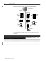
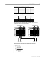
ControlLogix Gateway A
Port A
IP Address
130.130.130.7
Port B
9–5
ControlLogix Gateway B
Ethernet
Link 1 Link 2
IP Address
130.130.130.8
Port A
Port B
Link 3 Link 4
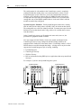
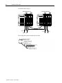
For example, we need to tell the DHRIO module on the left the path we want a
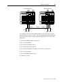
message to take from Link 1 to Link 3. Let’s draw that path in the physical diagram
and write out each step the message will take along that path. Let’s write out the
path to link 3:
1. Start at the DHRIO module in Gateway A.
2. Go over the backplane
3. Go to the ENET module in slot 1.
4. Go out onto the Ethernet network.
5. Go to the ENET module at IP address 130.130.130.8 in Gateway B.
6. Go over the backplane.
7. Go to the DHRIO module in slot 1.
8. Channel A is Link 3.
Publication 1756-6.5.7 – February 1999