1
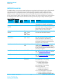
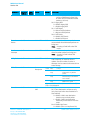
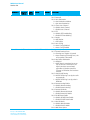
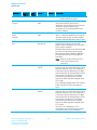
RM024 User Manual Version 2.4 0x4E). Any changes to the Digital Inputs that occur while a utility retransmission is occurring are not transmitted unless the change persists until all utility retries have been sent or an acknowledge was received. Therefore, this feature should only be used for slow-moving changes that occur less than the time it takes to expend all retries. Remote I/O is disabled when the Force 9600 pin is set at boot. Remote I/O control lines occur in pairs, with the Digital Input on the local radio driving a Digital Output on the remote radio and vice-versa. This makes Remote I/O useful for both point-to-point and point-tomultipoint networks. Multipoint-to-point networks do not benefit from using a single pair of lines as the central point isn’t able to tell where the line change was sourced. Multiple control lines are available though, so up to four pairs of lines can be used simultaneously. Likewise, analog inputs can be used (Address 0x57, bit 4) as the input (with a PWM output on the remote radio), though analog states are only transmitted when a utility packet is sent, which are only triggered by the change of a Digital Input. Threshold settings are not available on analog Inputs. Output lines are initialized at boot according to Remote I/O Status (Address 0xC9-0xCA) for the digital lines and PWM_Init (Address 0xC8) for the PWM output. Which control lines are used in Remote I/O is set by the Remote I/O Control bit field (Address 0x60). Note that TxD/RxD is one pair of Remote I/O lines available. If this pair is used, the module does not respond to commands and is not able to transmit or receive serial data. If this pair is enabled, Force 9600 must be low at boot to disable Remote I/O if serial communications are desired. Table 8: Remote I/O Control bit fields (Address0x60) Address 0x60, Bit Input Bit 0 set GIO_4 Output GIO_0 1 Bit 1 set GIO_8 Bit 2 set GIO_7 GIO_3 Bit 3 set CMD/Data GIO_2 Bit 4 set RTS CTS Bit 5 set RXD TXD Bit 6 clear, Bit 7 clear All I/O are Outputs Bit 6 set, Bit 7 clear All I/O are Inputs Bit 7 set 1. GIO_1 Inputs and outputs are as specified in table GIO_8 (Pin 18) on board revisions 0050-00203 Rev 0 and 0050-00196 rev 2 (and below) is internally not connected. This pin is unavailable as a GPIO on these boards. Tips: When using GIO_7/GIO_3 Pairs, the input/output will be digital unless Remote Analog Enable bit is set (Address 0x57, bit 4) in which case the input is Analog and the output is PWM. TXD and RXD are not available for UART serial data when used as in Remote I/O. Force 9600 must be Low on boot to disable Remote I/O Mode and issue commands. When not using pairs (bit 7 clear), one radio should have all I/O as inputs and the other radio or radios should have all I/O as output. Remote I/O Mode must be enabled on both the local and remote radio and the Remote I/O Control Bit must be set for the same pair on both radios. All I/O state information for all lines is transmitted when any update is triggered. Thus, on the receiving radio any enabled output pins will be updated, regardless of whether those pins were enabled on the transmitting radio. Americas: +1-800-492-2320 Option 2 Europe: +44-1628-858-940 Hong Kong: +852-2923-0610 www.lairdtech.com/wireless 21 CONN-GUIDE-RAMP24-0413