1
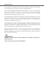
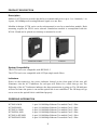
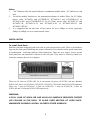
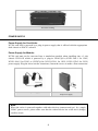
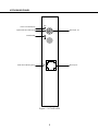
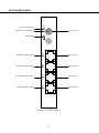
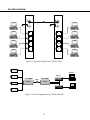
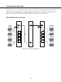
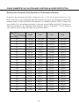
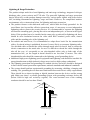
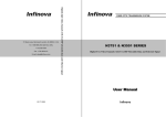
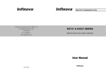
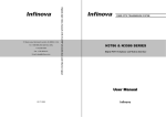
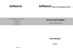
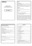
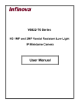
FIBER OPTIC TRANSMISSION SYSTEM 51 Stouts Lane, Monmouth Junction, NJ 08852, U.S.A. Tel: 1-888-685-2002(toll-free, USA) 1 SERIES 1-732-355-9100 Fax:1-732-355-9101 0ESV$XWR6HQVLQJ(WKHUQHW7UDQVFHLYHU E-mail: [email protected] User Manual Infinova V2.3 1012 Contents SERVICE NOTICE .................................................................................................................. 1 PRODUCT DESCRIPTION..................................................................................................... 2 ORDERING INFORMATION ................................................................................................. 2 INSTALLATION...................................................................................................................... 3 POWER SUPPLY..................................................................................................................... 4 N3784XA/XB PANEL ............................................................................................................. 5 N3784XA/XB-4 PANEL .......................................................................................................... 6 N3784XA/XB-4FE PANEL...................................................................................................... 7 SYSTEM DIAGRAM .............................................................................................................. 8 TRANSMISSION REPEATER ................................................................................................ 9 CABLE DIAMETER CALCULATION AND LIGHTNING & SURGE PROTECTION ..... 10 SERVICE NOTICE The installation of this product should be made by qualified personnel. Do not attempt to service this product yourself. Refer all servicing to qualified personnel. If you require information during installation of this product or if service seems necessary, contact the local suppliers or Infinova at 1-732-355-9100 in 51 Stouts Lane, Monmouth Junction, NJ 08852 U.S.A. You must obtain a Return Authorization Number and shipping instructions before returning any product for service. Our obligation under this warranty is limited only to the repair or replacement of any of our products, provided that products are used within the specified ratings and applications, and that products are applied in accordance with good engineering practices, and that products are proved by our examination to be defective. This warranty does not extend to any Infinova products which have been subject to acts of accident, misuse, abuse, neglect, improper application or installation, improper operation or maintenance, connection to an improper voltage supply or to materials which have been altered or repaired outside an authorized Infinova factory repair center. Information provided by Infinova is accurate and reliable. However, no responsibility is assumed by Infinova for its use; nor for any infringements of other rights of third parties which may result from its use. No license is granted by implications or otherwise under any patent or patent rights of Infinova. WARNING TO REDUCE THE RISK OF FIRE OR SHOCK HAZARD, DO NOT EXPOSE THIS PRODUCT TO RAIN OR MOISTURE. DO NOT LOOK INTO OPTICAL PORTS WITH POWER ON. 1 PRODUCT DESCRIPTION Description Infinova’s N3784 series provides the ability to transmit and receive up to 1 or 4 channels, 1 or 4 ports, 10/100Mbps auto sensing Ethernet signal over one fiber. Modular in design, N3784 series can be rack-mounted or used as a stand-alone module. Rack mounting requires the N3910 series subrack. Stand-alone module is accomplished with the N3910-1S and can be placed on a desktop or mounted to a wall. Stand-alone module Card unit System Compatibility The N3784 series are compatible with IEEE 802.3. The N3784 series are compatible with 9/125μm single-mode fibers. Indicators Power on the transceiver, the power indicator located on the front panel of the unit will illuminate, also the ACT indicators for each port will flicker for a while then go out. The flickering of the ACT indicators indicates the data transmission is going on. The OP indicator will turn red once the power is on and the optical link is not established. The OP lamp will go out as soon as the optical link is established properly. ORDERING INFORMATION N3784XA-M/R N3784XB-M/R N3784XA-4-M/R N3784XB-4-M/R N3784XA-4FE-M/R N3784XB-4FE-M/R 1-port 10/100 Mbps Ethernet Trx module/Card, 1 fiber 1-port 10/100 Mbps Ethernet Trx module/Card, 1 fiber 4-port 10/100 Mbps Ethernet Trx module/Card, 1 fiber 4-port 10/100 Mbps Ethernet Trx module/Card, 1 fiber 4-port 10/100 Mbps Ethernet Trx module/Card, 1 fiber 4-port 10/100 Mbps Ethernet Trx module/Card, 1 fiber 2 Notes: 1. “-M” followed after the model indicates a standalone module while “-R” indicates a card unit. 2. For all the models listed above, the transmission distance is within 25km. For 25~50km, please order N3784XA and N3784XB-55, N3784XA-4 and N3784XB-4-55, or N3784XA-4FE and N3784XB-4FE-55; for 50~75km, please order N3784XC-55 and N3784XC-49, N3784XC-4-55 and N3784XC-4-49, or N3784XC-4FE-55 and N3784XC-4FE-49. 3. It is suggested that the data rate of the camera be set to 6Mbps or below (generally 4Mbps or 6Mbps) so as to watch smooth video. INSTALLATION To install Card Units Push the card unit along the guide rails (not in spaces between the rails). There is an Infinova logo on the front panel indicating the proper orientation. Press hard to make good connection to motherboard - loud snap indicates firm connection. There are two captive screws on the front panel that can fasten the card unit to the sub-rack. They must be locked by hand in a clockwise manner (do not over tighten). Full load of N3910-18S There are 18 slots on N3910-18S. So it can mount 18 pieces of N3784 card unit. Besides N3910-18S, there are N3910-1S, N3910-2S, N3910-3S, N3910-4S and N3910-15R optional. There are 1 slot on N3910-1S, 2 slots on N3910-2S, 3 slots on N3910-3S, 4 slots on N3910-4S and 15 slots on N3910-15R respectively. WARNING: A FULL LOAD OF N3910-15R AND N3910-18S SUBRACK REQUIRES FORCED AIR COOLING IN THE RACK. TO AVOID OVER HEATING OF CARD UNITS, WHENEVER POSSIBLE, INSTALL IN EVERY OTHER SUBRACK. 3 Forced air cooling POWER SUPPLY Power Supply for Card Units: N3784 card unit is powered by a plug-in power supply that is offered with the appropriate desk chassis or EIA 19" subrack. Power Supply for Module: N3784 card unit can be converted into a stand-alone module when installing into a 1-slot chassis N3910-1S which is powered by a plug-in 24VAC@1A (N3921-24A-1 for 120V; N3921-24A-2 for 230V) or 12VDC@1A (N3921-12D-1 for 120V; N3921-12D-2 for 230V) power supply. Plug the wires into the connectors; fasten the screws to make a firm connection. Connection between stand-alone module and power supply N3921 power supply Note: When the series is powered together with other devices (cameras and etc.) by a single 24VAC power source, please make sure that the related device has a full-wave (bridge) rectifier circuit. 4 N3784XA/XB PANEL PWR Power on indicator(red) OP Optical link loss indicator(red) Optical port, FC Chassis GND ACT Data active indicator(green) Ethernet port Figure 1. N3784XA/XB 5 N3784XA/XB-4 PANEL PWR Power on indicator(red) OP Optical link loss indicator(red) Optical port, FC Chassis GND ACT Data active indicator(green) Ethernet port 1 ACT Ethernet port 2 Data active indicator(green) ACT Data active indicator(green) Ethernet port 3 ACT Data active indicator(green) Ethernet port 4 Figure 2. N3784XA/XB-4 6 N3784XA/XB-4FE PANEL PWR Power on indicator(red) OP Optical port, FC Optical link loss indicator(red) Chassis GND ACT Ethernet port 1 Data active indicator(green) ACT Ethernet port 2 Data active indicator(green) ACT Ethernet port 3 Data active indicator(green) ACT Ethernet port 4 Data active indicator(green) Figure 3. N3784XA/XB-4FE 7 SYSTEM DIAGRAM Figure 4. System Diagram for N3784XA/XB-4 Figure 5. System Diagram for N3784XA/XB-4FE 8 TRANSMISSION REPEATER The N3951 series is used between transceivers to extend the transmission distance of fiber optical system. It magnifies the optical signal received from transmitter, and sends it to receiver. By using a N3951, the transmission distance of the system is doubled. Typical application connection Figure 6. Transmission repeater 9 CABLE DIAMETER CALCULATION AND LIGHTNING & SURGE PROTECTION Relation between 24VAC Cable Diameter and Transmission Distance In general, the maximum allowable voltage loss rate is 10% for AC-powered devices. The table below shows the relationship between transmission power and maximum transmission distance under a certain specified cable diameter, on condition that the 24VAC voltage loss rate is below 10%. According to the table, if a device rated at 50W is installed 17-meter away from the transformer, the minimum cable diameter shall be 0.8000mm. A lower diameter value tends to cause voltage loss and even system instability. Diameter (mm) 0.8000 1.000 1.250 2.000 10 283 (86) 451 (137) 716 (218) 1811 (551) 20 141 (42) 225 (68) 358 (109) 905 (275) 30 94 (28) 150 (45) 238 (72) 603 (183) 40 70 (21) 112 (34) 179 (54) 452 (137) 50 56 (17) 90 (27) 143 (43) 362 (110) 60 47 (14) 75 (22) 119 (36) 301 (91) 70 40 (12) 64 (19) 102 (31) 258 (78) Distance (ft / m) Power (W) 80 35 (10) 56 (17) 89 (27) 226 (68) 90 31 (9) 50 (15) 79 (24) 201 (61) 100 28 (8) 45 (13) 71 (21) 181 (55) 110 25 (7) 41 (12) 65 (19) 164 (49) 120 23 (7) 37 (11) 59 (17) 150 (45) 130 21 (6) 34 (10) 55 (16) 139 (42) 140 20 (6) 32 (9) 51 (15) 129 (39) 150 18 (5) 30 (9) 47 (14) 120 (36) 160 17 (5) 28 (8) 44 (13) 113 (34) 170 16 (4) 26 (7) 42 (12) 106 (32) 180 15 (4) 25 (7) 39 (11) 100 (30) 190 14 (4) 23 (7) 37 (11) 95 (28) 200 14 (4) 22 (6) 35 (10) 90 (27) 10 Lightning & Surge Protection The product adopts multi-level anti-lightning and anti-surge technology integrated with gas discharge tube, power resistor and TVS tube. The powerful lightning and surge protection barrier effectively avoids product damage caused by various pulse signals with power below 4kV, including instantaneous lightning, surge and static. However, for complicated outdoor environment, refer to instruction below for lightning and surge protection: The product features with dedicated earth wire, which must be firmly grounded. As for surveillance sites beyond the effective protection scope, it’s necessary to erect independent lightening rods to protect the security devices. It’s recommended to separate the lightning rod from the mounting pole, placing the rod on an independent pole, as shown in the figure below. If the product has to be installed on the same pole or pedestal for lightning rod, there should be strict insulation between the video cable BNC terminal, power cable, control cable and the standing pole of the lightning rod. For suburb and rural areas, it’s recommended to adopt direct burial for the transmission cables. Overhead wiring is prohibited, because it’s more likely to encounter lightning strike. Use shielded cables or thread the cables through metal tubes for burial, thus to ensure the electric connection to the metal tube. In case it’s difficult to thread the cable through the tube all the way, it’s acceptable to use tube-threaded cables only at both ends of the transmission line, yet the length in burial should be no less than 15 meters. The cable sheath and the tube should be connected to the lightning -proof grounding device. Additional high-power lightning-proof equipment and lightning rods should be installed for strong thunderstorm or high induced voltage areas (such as high-voltage substation). The lightning protection and grounding for outdoor devices and wires should be designed in line with the actual protection requirement, national standards and industrial standards. The system should perform equipotential grounding by streaming, shielding, clamping and earthing. The grounding device must meet anti-interference and electric safety requirements. There should be no short-circuiting or hybrid junction between the device and the strong grid. Make sure there’s a reliable grounding system, with grounding resistance below 4Ω (below 10Ω for high soil resistivity regions). The cross-sectional area of the earthing conductor should be no less than 25mm². LPZOA 30° LPZOB 30° Lightning rod Front device for surveillance system Mounting pole for front device Separated layout for the lightning rod and the standing pole 11 FIBER OPTIC TRANSMISSION SYSYEM 3732 & 3532 SERIES Digital one video with 4-ch audio-and-data User Manual Infinova V2.7 1308