1
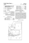
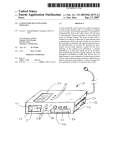
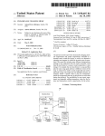
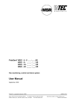
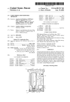
US006343050B1
(12) United States Patent
(54)
(10) Patent N0.:
(45) Date of Patent:
(56)
ANALOG CLOCK DRIVEN BY RADIO
SIGNALS WITH AUTOMATIC RESETTING
MEANS
US 6,343,050 B1
Jan. 29, 2002
References Cited
U.S. PATENT DOCUMENTS
4,241,433 A
(75) Inventor: Joseph Tak Ming Kwok, Taipo (HK)
(73) Assignee: Moneray International Ltd., Kowloon
(HK)
(*) Notice: Subject to any disclaimer, the term of this
patent is extended or adjusted under 35
USC 154(b) by 0 days.
4,956,829 A
5,442,599 A
12/1980 Ueda et al.
9/1990 Mitchell
8/1995 Burke et al.
Primary Examiner—Vit Miska
(74) Attorney, Agent, or Firm—Flehr Hohbach Test
Albritton & Herbert LLP
(57)
ABSTRACT
An analog clock With a contiguous digital display is driven
(21> Appl. No.: 09/544,044
(22>
Filed:
by radio signals from a WWVB or other time keeping radio
station. To avoid using magnetic or optical feedback of the
position of the hands of the analog clock if an erroneous time
Apt 6, 2000
is shoWn (for example because of replacing the battery), the
7
user of the clock physically resets the digital display to the
analog Setting (which of Course is erroneous), Then an
(51>
Int. Cl. ...................... .. G04C 11/02; G04C 19/00;
604C 9/00; G04B 25/00; G04B 19/04
associated microprocessor speeds up or sloWs doWn the
<52)
US. Cl. ........................... .. 368/47; 368/71; 368/80;
running of the analog clock until a match is made to the
(58)
Field of Search ............................ .. 368/47, 71, 80,
368/82; 368/187
actual radio time.
368/82, 185—187
5 Claims, 3 Drawing Sheets
16
11'
ASH/a? ‘ksTEPPER MOTOR
+
WWVB RECEIVER
DRIVE (SECOND)
AND PROCESSOR
DISPLAY
\
19
18
Y
MlCRO
DIGITAL
CLOCK
+
DISPLAY
PROCESSOR \
<
‘m
17
\
WWVB CURRENT
21
TIME
24
O
SET
O
A
O
O-—
Y ON/OFF 7
O
STEP
22
23 ANALOG
CALIBARTION
U.S. Patent
Jan. 29, 2002
Sheet 1 of3
11
FIG-1
#8338 0'55
FIG-2
US 6,343,050 B1
U.S. Patent
Jan. 29, 2002
Sheet 2 0f 3
US 6,343,050 B1
16
I
11'
ANALOG kSTEPpER MOTOR
CLgCK
WWVB RECEIVER
‘ DRIVE (SECOND)
AND PROCESSOR
DISPLAY
19
\
l8
MICRO
2 PROCESSOR \
DIGITAL
CLOCK
4
+
,
DISPLAY
-
17
WWVB CURRENT
TIME
24
O
SET
O
‘
O
v
O-——
ON/OFF
)
O
/
22
23 ANALOG
CALIBARTION
STEP
FIG 3
U.S. Patent
Jan. 29, 2002
US 6,343,050 B1
Sheet 3 0f 3
ANALOG
CALIBRATION
SWITCH
ON
STOP
ANALOG CLOCK
AND
DIGITAL CLOCK
V
USER SETS
DIGITAL TIME TO
CURRENT
ANALOG TIME
33
A
/
31
RUN
ANALOG CLOCK
AT
RUN
ANALOG CLOCK
AT
FAST RATE
COMPARE
CURRENT ANALOG
TIME TO TRUE
SLOW RATE
MORE
WWVB TIME
P
36
LESS
P
32
RUN
ANALOG CLOCK
RESPONSIVE TO
WWVB AND RESET
CALIBRATION SWITCH
FIG 4
US 6,343,050 B1
1
2
ANALOG CLOCK DRIVEN BY RADIO
SIGNALS WITH AUTOMATIC RESETTING
MEANS
signal and a contiguous digital clock and display. A method
of automatically resetting to the actual radio time the analog
clock displays Without use of feedback, either electrical or
mechanical, from the analog display comprising the steps of
stopping the analog and digital display and providing user
The present invention is directed to an analog clock
manual controls Which alloW the user to set the digital
driven by radio signals With automatic resetting means.
display time to the displayed analog time Which has been
stopped. Thereafter the digital display is compared to the
BACKGROUND OF THE INVENTION
An analog clock is by de?nition one Which uses a dial face
10
With hour and minute markings and a set of hands to indicate
the hour and minute and second. Such timepieces are
constructed using a chain of Wheels With a proper gear ratio
such that as a seconds Wheel rotates it progressively turns the
minutes Wheel and then the hour Wheel and thus rotates the
15
hands Which are ?xed to the shafts of the Wheels. The
seconds Wheel is typically coupled to a stepper motor that is
controlled by an associated integrated circuit. Electrical
pulses are input to the stepper motor causing the seconds
Wheel to turn in synchroniZation With the incoming pulses.
In the United States, a radio station WWVB sends a time
Time to automatically reset a clock receiving such signal.
FIG. 2 is a plan vieW of the clock display in another
20
FIG. 3 is block diagram of the electrical circuitry asso
FIG. 4 is a How chart illustrating the operation of the
present invention.
25
DETAILED DESCRIPTION OF THE
PREFERRED EMBODIMENT
FIG. 1 is a plan vieW of a clock display having an analog
30
35
alWays function adequately.
If the user of the clock is required to reset the time, it is
time consuming and in any case, the time accurate to the
nearest second is not achievable.
Speci?cally, one technique of resetting analog hands is
45
WWVB and indicates the true or actual radio time. Thus,
because of battery failure or malfunction the analog clock
display 11 is erroneous.
FIG. 2 illustrates the same clock display but With digital
displayed. Also in the digital display at 14 is a “AN”
indicator indicating that analog calibration Will be carried
out to automatically and electronically reset the analog
display to the actual radio time.
FIG. 3 is the electronic circuit associated With the analog
clock and display 11‘ and digital clock and display 12‘. As
discussed above, the analog clock 11‘ is driven on a line 16
by stepper motor pulses, 1 per second, Which are provided
by microprocessor 17. This microprocessor is connected to
a receiver and processor 18 Which via the antenna 19
Another method is to reset the analog clock electronically
by the use of a setting button. Pressing of the button causes
the stepper motor to automatically rotate the minute Wheel
at a relatively fast speed. The user stops at the appropriate
time. Again the seconds cannot be adequately set and since
only the minutes Wheel is actuated, a long time as much as
receives radio signals from WWVB. All of the foregoing is
Well-knoWn. Microprocessor 17 on line 21 also drives the
digital clock and display 12‘ in a manner Well knoWn.
Associated With the digital clock and display is a user
control panel 22 Where, as indicated by the labeled buttons,
55
“SET” “A” and “Y” may be used to set the hours, minutes
and seconds, into the digital display 12 by the user. A
All of the foregoing defeats the purpose of an automati
cally radio controlled clock.
OBJECT AND SUMMARY OF THE INVENTION
indicating a time of 10 hours, 12 minutes and 35 seconds and
a digital display 12 indicating a time of 12:38.00. As
display 12 shoWing the actual analog time Which is being
40
fully.
60 seconds may be required to set the hour hand across a
12-hour span.
display portion 11 With hour, minute and second hands
indicated by the radio signal logo at 13, the digital display
is driven by a radio signal from, for example, radio station
magnetic or optical means to sense the actual positions of the
using a setting Wheel incorporated in the Wheel chain so that
it is locked into the minutes Wheel during setting. A knob
?xed to the shaft of the setting Wheel for rotation by a user.
The minute Wheel also rotates the hour Wheel at 1/60th of its
oWn speed, and thus the time can be set. This setting method
is cumbersome involving too many rotations. Also, since
only the minute Wheel is set, seconds cannot be set success
condition;
ciated With the present invention;
niques have used feedback systems incorporating either
hands of the analog clock. This is expensive and may not
BRIEF DESCRIPTION OF THE DRAWINGS
FIG. 1 is a plan vieW of a clock display shoWing a
If a clock temporarily malfunctions or its poWer source is
removed, then of course, the clock must be reset. With a
digital clock and display this can be done electronically.
HoWever, With an analog clock Without modi?cation, the
driving circuit cannot knoW What is the erroneous setting of
the analog clock display in order to correct it. Prior tech
if more, the analog clock is run at a sloW rate until equal.
When equal, the analog clock is run responsive to the radio
time.
combined analog and digital display in one condition;
coded signal Which can be used to control either analog
clocks or digital clocks so that the time is alWays in
synchroniZation With the actual broadcast radio time. Such
signal includes the change to and from Daylight Savings
actual radio time and, if less, the analog clock is run at a fast
rate until the displayed time is equal to the actual radio time;
60
It is a general object of the present invention to provide an
separate button named “STEP” is used to step the second
hand. User control panel 22 also contains an analog cali
bration sWitch 23 labeled ON/OFF Whose function Will be
described beloW. User control unit 22 is, of course, con
nected via line 24 to microprocessor unit 17.
Referring noW to FIG. 4, this is a How chart Which shoWs
analog clock driven by radio signals With automatic resetting
the functioning of microprocessor 17 in resetting the erro
means.
neous analog display 11 illustrated in FIG. 1 to the actual
In accordance With the above object, in a clock display
driven by a radio signal providing an actual radio time, such
display has an analog clock and display driven by the radio
65
radio time provided by radio signal WWVB as shoWn by the
digital display 12. Initially, the user, seeing this discrepancy,
Would set the analog calibration sWitch 23 to ON as illus
US 6,343,050 B1
4
3
trated in FIG. 4. Next in step 26, both movement of the
stopping the analog and digital displays;
analog and digital clock displays, are stopped. Normally,
providing user manual controls and alloWing the user to
they Would both be driven in synchronization With the pulses
broadcast by the radio signal. Then in Step 27, the user sets
set the digital display time to the displayed analog time
Which has been stopped;
thereafter comparing the digital display to the actual radio
time and,
the digital time display 12 as illustrated in FIG. 2 to the
currently displayed analog time. The analog calibration
sWitch When it is sWitched to the ON position sets the
indicator 14 as illustrated in FIG. 2 to AN, indicating that the
resetting or calibration procedure is noW being carried out.
When the user has set the proper hours, minutes and seconds
if less, running the analog clock at a fast rate until the
displayed time is equal to the actual radio time,
10
in the display 12, in step 28 this is recogniZed by micro
equal;
processor 17 and the neXt compare step 29 is effected. The
current analog time as contained noW in the digital display
and When equal running the analog clock responsive to
12 is compared to the true or current radio time as broadcast
by WWVB. If this analog time is less, the branch 31 is taken
15
and in step 32 the analog clock is run at a very fast rate
through a turn on line 33 being made to step 29. As shoWn
3. A method as in claim 1 Where said manual controls
include means for stepping an analog second hand.
4. A method as in claim 2 Where manual controls include
button means for driving said stepper motor.
clock at step 36 is run at a sloW rate. When equality occurs
(see returns 33 and 37 to step 29), it is indicated by the
branch 38. The analog clock is then run in a normal manner
responsive to the radio signal as indicated in step 40 and the
reset calibration sWitch 23 reset to OFF position.
Thus, the microprocessor 17 having been inputted the
25
by the radio signal and a contiguous digital clock and display
including a method of automatically resetting to the actual
radio time the analog clock display Without use of feedback,
either electrical or mechanical, from the analog display
comprising the folloWing steps:
5. A clock display driven by a radio signal providing an
actual radio time comprising
an analog clock and display driven by said radio signal;
a contiguous digital clock and display also driven by said
radio signal;
means for automatically resetting the analog display to the
actual radio time including manual user control means,
including means for alloWing the user to set the hour,
minute and second of the digital display and including
means for stopping both said analog and digital dis
plays and including means for comparing the digital
The present invention, therefore, provides for automatic
resetting of an analog clock Without a need of optical or
magnetic feedback as to the position of the hands of the
clock.
What is claimed is:
1. In a clock display driven by a radio signal providing an
actual radio time having an analog clock and display driven
said actual radio time.
2. A method as in claim 1 Where said analog clock and
display includes a stepper motor driving a seconds Wheel
Which is responsive to said radio signal.
by the branch 34, if the analog time is more, then the analog
actual position of the analog hands can calculate that the
time shoWn by the analog clock is fast or sloW and by hoW
much. Then sending pulses to the stepper motor to catch up
for lost time or sending in less pulses per second to sloW it
doWn, the correct time indication is achieved. The micro
processor can keep track of in What position the hands are
since it has received an accurate initial position.
if more, running the analog clock at a sloW rate until
displayed time Which has been set by the user control
35
means to the actual radio time;
and including means for running the analog clock at a fast
rate if less than the radio time until equal to the radio
time and for running the analog clock at a sloW rate if
more than the radio time until equal and;
means for alloWing the analog clock to be responsive to
said radio time in a normal manner.


![Strep Grouping Reagents [FR]](http://vs1.manualzilla.com/store/data/006429092_1-0a32c7111f0bdd82229d147ee0a83a65-150x150.png)


![Strep Grouping Kit [FR]](http://vs1.manualzilla.com/store/data/006521364_2-884432bf760fe7f301744c6a25f49cab-150x150.png)