1
2.0 Basic Components of the PLC Platform
In order to give students an opportunity to experience how computer automation and control is
accomplished in a manufacturing environment, a demonstration apparatus was built containing actuation
and sensing devices, a computer interface, feedback control, and an Allen Bradley MicroLogix 1500
programmable logic controller. This platform can be utilized by the instructor in a classroom
environment for demonstration purposes, as well as by students as part of an active learning environment
within or outside of the classroom. The apparatus is flexible so as to allow students to investigate how a
basic control system works to perform an automated task, including the basics of how the various
components of the system function and communicate with each other, and to investigate the theory
associated with proportional, integral, derivative control and associated techniques.
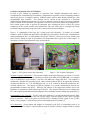
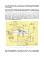
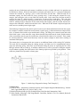
Figure 1 is a photograph of the basic PLC system used in this laboratory. It consists of a personal
computer, which is loaded with both RSLinx and RSLogix 500 software, used for PLC communication
and programming the PLC, an Allen Bradley MicroLogix 1500 PLC, and a series of relays, switches and
power sources, which are used as representative I/O components that a typical PLC would control. A
description of each of the components of the system follows.
Rotating Gear
Cooling
Blinking Red
1796 Input
PL
Part
Gear
Figure 1 – PLC System Used in this Laboratory
24 VDC
24 VDC
/
120
120 VAC
Input
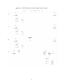
Figure 2 – PLC System Components
Personal Computer and Software: The personal computer used in this laboratory (see Figure 1) is a Dell
computer, with Pentium III processor operating at a speed of 996 MHz, and 256 MB RAM. It is equipped
with a CD ROM drive (not writeable), a zip drive (100 MB) and a floppy disk drive. The computer is
loaded with a Windows XP operating system. Other software loaded on the PC to support this laboratory
includes both RSLinx, rev. 2.43 and RSLogix 500, ver. 6.30, written for Rockwell Automation, Inc.
networks and devices. The purpose of RSLinx software is to provide communication between the
programmable controller and the PC. RSLogix 500 software is the application software used in the
laboratory in conjunction with the MicroLogix 1500 PLC. This software allows the user to configure the
PLC and to upload and download control programs, more commonly known as ladder logic programs [2].
Programmable Logic Controller: The PLC used in this laboratory is an Allen Bradley MicroLogix 1500,
1764-24BWA. It contains a base unit with a power supply, input and output circuits, and a 1764-LRP
Series C processor. It has a line power of 120/240 VAC, 8 standard 24 VDC inputs, 4 fast 24 VDC
inputs, 12 relay outputs, 2 isolated relays per unit, and 4 high speed I/O (20 kHz) [3].
I/O Components: Several inputs and outputs are connected to the PLC to demonstrate some of its
capability, as shown in Figure 2. Inputs include an array of ON/OFF switches. Outputs include a cooling
2