1
(3) Click on the pull down menu “Remote Run” in the upper left corner of the screen and select the
“Download” option. This will download the currently opened program to the PLC. With the ladder logic
program “PLC Lab Sim2.RSS” downloaded to the PLC, there are two options for running its ladder logic:
(a) The PLC can simply be powered on with 120 VAC and ladder logic operated using the PLC and
associated hardware without the RSLogix 500 software running; or (b) The PLC can be operated in
conjunction with the RSLogix 500 software running interactively at the same time. This is done by using
the “Remote Run” pull down menu in the upper left corner of the RSLogix 500 software and selecting the
“Go Online” option. Running “online” with the ladder logic software open together with the PLC
operating allows the user the additional option of modifying inputs to the ladder logic (i.e., turning on
switches, etc.) through software input.
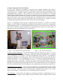
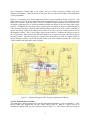
(4) To test the ladder logic features, flip the toggle switch “0” of the 1796 SIM1500 Input Simulator to the
up position. Note that the fan turns on. This occurs because output 5 (O:0/5) of the PLC is activated
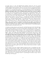
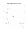
from 0, OFF to 1, ON. Referencing rung 1 of the ladder logic diagram in Appendix A, it is seen that
O:0/5 (portrayed as a load on the right side of rung 1 of the ladder logic diagram) is activated when input
4 (I:0/4, a ladder logic switch) is activated to 1, ON. This is done by physically moving toggle switch 0
of the 1796 SIM1500 Input Simulator in the up position, completing the 24 VDC circuit. The wiring
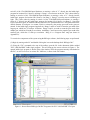
diagram of Figure 3 shows how all this is accomplished via hardware. Here, it is seen that 120 VAC is
brought in to power the fan through a relay (left side relay). This relay acts as a switch, which is activated
only when the other side (24 VDC side) of the relay closes the contacts to the 120 VAC circuit via a 24
VDC signal from the PLC. This 24 VDC signal is activated only when output 5 (O:0/5) on the PLC is
given a value of “1.” And, of course, as stated earlier, this output is activated through input I:0/4. The
input I:0/4 is physically connected to the high (plus) side of the 24 VDC circuit via switch 0 of the 1796
SIM 1500 Input Simulator. The ground side of this circuit is connected to the DC COM (common) of the
PLC on the input side, as shown in Figure 14. The fan can also be turned on by entering a value of “1”
directly into the ladder logic program for location N9:4, Source A at Rung 1. This can also be done by
opening the N9 folder (lower left window of the RSLogix 500 software) and entering a value of “1” in
location 4. The fan can be turned off by entering a value of “0” in location N9:4 using either of these
methods. Finally, it is important to note that activating the fan using a 24 VDC relay switch, isolates the
120 VAC circuit from the PLC and switching functions, making the operation of turning the fan on safer.
(5) Next, flip the toggle switch “1” of the 1796 SIM1500 Input Simulator to the up position. Note that the
blinking red light turns on. This occurs because output 0 (O:0/0) of the PLC is activated from 0, OFF to
1, ON. Referencing rung 2 of the ladder logic diagram in Appendix A, it is seen that O:0/0 (portrayed as
a load on the right side of rung 1 of the ladder logic diagram) is activated when input 5 (I:0/5, a ladder
logic switch) is activated to 1, ON. This is done by physically moving toggle switch 1 of the 1796
SIM1500 Input Simulator in the up position, completing the 24 VDC circuit. The ladder logic also shows
a time base switch, or timing delay, S:4/13, in-line with the I:0/5 input and I:0/0 output. This software
delay is actually what causes the red light to turn on and off at regular intervals, that is, to blink. The
wiring diagram of Figure 3 shows how the red blinking light is activated via hardware. Here, it is seen
that 24 VDC power is brought from the input side of the PLC over to the output side through output 0
common (VDC 0). The +24 VDC connection is completed through VDC 0 and O:0/0 when I:0/5 is
turned ON. The 24 VDC common side is connected from the 24 VDC common screw terminal (COM)
on the input side of the PLC, through the 24 VDC screw connector (see Figure 14) and then to the ground
(-) side of the red blinking light. The red blinking light can also be turned on by entering a value of “1”
directly into the ladder logic program for location N9:5, Source A at Rung 2. This can also be done by
opening the N9 folder (lower left window of the RSLogix 500 software) and entering a value of “1” in
location 5. The red blinking light can be turned off by entering a value of “0” in location N9:5 using
either of these methods.
5