1
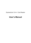
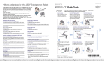
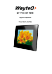
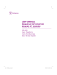
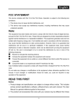
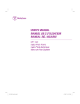
EVB-USB2240-IND User Manual Revision B Copyright © 2009 SMSC or its subsidiaries. All rights reserved. Circuit diagrams and other information relating to SMSC products are included as a means of illustrating typical applications. Consequently, complete information sufficient for construction purposes is not necessarily given. Although the information has been checked and is believed to be accurate, no responsibility is assumed for inaccuracies. SMSC reserves the right to make changes to specifications and product descriptions at any time without notice. Contact your local SMSC sales office to obtain the latest specifications before placing your product order. The provision of this information does not convey to the purchaser of the described semiconductor devices any licenses under any patent rights or other intellectual property rights of SMSC or others. All sales are expressly conditional on your agreement to the terms and conditions of the most recently dated version of SMSC's standard Terms of Sale Agreement dated before the date of your order (the "Terms of Sale Agreement"). The product may contain design defects or errors known as anomalies which may cause the product's functions to deviate from published specifications. Anomaly sheets are available upon request. SMSC products are not designed, intended, authorized or warranted for use in any life support or other application where product failure could cause or contribute to personal injury or severe property damage. Any and all such uses without prior written approval of an Officer of SMSC and further testing and/or modification will be fully at the risk of the customer. Copies of this document or other SMSC literature, as well as the Terms of Sale Agreement, may be obtained by visiting SMSC’s website at http://www.smsc.com. SMSC is a registered trademark of Standard Microsystems Corporation (“SMSC”). Product names and company names are the trademarks of their respective holders. SMSC makes the following part-numbered device available for purchase only by customers who are xD-Picture Card licensees: USB2240. By purchasing or ordering any of such devices, Buyer represents, warrants, and agrees that Buyer is a duly licensed Licensee under an xD-Picture CardTM License Agreement with Fuji Photo Film Co., Ltd., Olympus Optical Co., Ltd., and Toshiba Corporation; and that Buyer will maintain in effect such xD-Picture Card license and will give SMSC reasonable advance notice of any termination or expiration of such xD-Picture Card license, but in no event less than five days advance notice. SMSC may discontinue making such devices available for purchase by Buyer and/or discontinue further deliveries of such devices if such xD-Picture Card license shall expire, terminate, or cease to be in force, or if Buyer is or becomes in default of such xD-Picture Card license. SMSC DISCLAIMS AND EXCLUDES ANY AND ALL WARRANTIES, INCLUDING WITHOUT LIMITATION ANY AND ALL IMPLIED WARRANTIES OF MERCHANTABILITY, FITNESS FOR A PARTICULAR PURPOSE, TITLE, AND AGAINST INFRINGEMENT AND THE LIKE, AND ANY AND ALL WARRANTIES ARISING FROM ANY COURSE OF DEALING OR USAGE OF TRADE. IN NO EVENT SHALL SMSC BE LIABLE FOR ANY DIRECT, INCIDENTAL, INDIRECT, SPECIAL, PUNITIVE, OR CONSEQUENTIAL DAMAGES; OR FOR LOST DATA, PROFITS, SAVINGS OR REVENUES OF ANY KIND; REGARDLESS OF THE FORM OF ACTION, WHETHER BASED ON CONTRACT; TORT; NEGLIGENCE OF SMSC OR OTHERS; STRICT LIABILITY; BREACH OF WARRANTY; OR OTHERWISE; WHETHER OR NOT ANY REMEDY OF BUYER IS HELD TO HAVE FAILED OF ITS ESSENTIAL PURPOSE, AND WHETHER OR NOT SMSC HAS BEEN ADVISED OF THE POSSIBILITY OF SUCH DAMAGES. SMSC EVB-USB2240-IND USER MANUAL Revision 1.0 (07-17-09) EVB-USB2240-IND User Manual Revision B 1 Overview The SMSC USB2240 is an Ultra Fast USB 2.0 Multi-Slot Flash Media Controller with Secure Digital (SD), MultiMediaCardTM (MMC), Memory Stick® (MS), and xD-Picture CardTM (xD) connectors. The EVB-USB2240-IND Revision B Evaluation Board demonstrates a standalone application for developers of the following applications: Flash Media Card Reader/Writer, printers, desktop and mobile PCs, consumer A/V, and flat panel displays, among others. 1.1 1.2 Features 36-Pin QFN (RoHS compliant) package. Supports these Media Types on Media I/F: - Secure Digital (SD2.0, HS-SD, HC-SD) - MultiMediaCardTM 4.2 - xD-Picture CardTM - Memory Stick® 1.43 - High Speed Memory StickTM - Memory Stick Pro-HGTM - Memory Stick Duo Memory Stick ProTM Internal FET power switch for all media types; no external power FETs needed. Optionally supports external configuration. - External I2C EEPROM for configuration options (optional). Low cost 4-Layer space saving design. Self-powered or bus-powered operation. Operates from a single voltage (+5.0 VDC, regulated) external power supply or from VBUS. Single onboard +3.3 VDC regulator. Optional +3.3 VDC media power LED indicator. Activity LED indicator. Single crystal clock source. General Description The EVB-USB2240-IND is an evaluation and demonstration platform featuring the USB2240 Ultra Fast USB 2.0 Flash Media Controller on a 4-layer RoHS compliant printed circuit board. The EVB-USB2240-IND is designed to demonstrate the unique features of this device using a low-cost PCB implementation. It is designed to support internal default configuration settings and an external I2C EEPROM (optional) for customized configured functionality. When an I2C EEPROM device is populated on the evaluation board it provides customizing via USB by using the SMSC provided USBDM utility, as required. The EVB-USB2240-IND is compatible with the following: - Microsoft® Vista - Windows® XP - Windows® ME - Windows® 2k SP4 - Apple® OSx - Linux® Mass Storage Class Drivers. Schematics, Layout, and Bill of Materials are included minimizing new product development time. Revision 1.0 (07-17-09) 2 USER MANUAL SMSC EVB-USB2240-IND EVB-USB2240-IND User Manual Revision B 2 Hardware Configuration 2.1 Hardware Description The EVB-USB2240-IND has one onboard regulator, which generates +3.3 VDC from an external +5 VDC regulated power supply. The USB2240 generates its own +1.8 VDC for internal use using onchip +1.8 VDC regulators. The internal 1.8 Volt regulator to the oscillator and PLL is turned off during suspend to minimize suspend current. The USB2240 consumes power from the 3.3 Volt supply. 2.1.1 USB2240 Configuration Default: The EVB-USB2240-IND has been set up to support internal default configuration as determined by the empty state (no valid signature ID) of the EEPROM immediately after reset. When no valid EEPROM image is detected, the Vendor ID, Product ID, Language ID, and Device ID, and a few other choices are set using ROM code defaults. EEPROM Option: The EVB-USB2240-IND can load configuration from an external two-wire, I2C EEPROM U2. The EEPROM must be installed in socket U2. The EEPROM may be pre-programmed before installation, or it can be programmed with the USB host using the provided SMSC USBDM application. This option allows access to all of the configuration registers and ID strings for the USB2240 device for detailed functional analysis and exercise as desired. The EVB-USB2240-IND is compatible with I2C EEPROMs from several manufacturers. The memory capacity must be at least 512 bytes. 2.1.2 Powered State LED An optional LED, LED1, indicates when +3.3 VDC power is present on the media sockets. 2.1.3 Activity LED A LED, LED3, indicates when the USB2240 is active, as defined by firmware. 2.1.4 Media Interface The USB2240 supports a wide array of devices. Media Interface accommodates all of the media types supported through the use of three media socket connectors. Adapters may be needed for some form factors. J1 supports SD media up to the specification limit of 4 bits wide. It also supports MMC media up to the specification 4.2 of 8 bits wide. J2 supports xD-Picture Card media. J3 supports MS, MS Pro, MS Duo, and MS Pro-HG media at up to the specification limit of 8 bits wide. Since these connectors are all on the same media bus, only one device is allowed to be inserted into any of these media socket connectors at one time for the Media Interface. 2.1.5 Connector Description The EVB-USB2240-IND has a standard USB style connector of type B for the upstream port. It also has a standard set of media storage style connectors, which supports popular flash media formats from the xD, MS, SD, and MMC families. Power is supplied via a 2.0 mm power jack. Table 2.1 lists all of the connectors. For more details on the pinout of the connectors please schematics in Figure 2.2 and Figure 2.3. SMSC EVB-USB2240-IND 3 USER MANUAL Revision 1.0 (07-17-09) EVB-USB2240-IND User Manual Revision B Table 2.1 Connector Description 2.1.6 CONNECTOR TYPE DESCRIPTION J1 SD/MMC4.0 SD/MMC I/F J2 xD xD I/F J3 MS/MS Duo/MS Pro-HG MS I/F J5 Header GPIO Test - DNP J6 Power Jack 2.0 mm +5 VDC Power Supply J7 USB B Upstream Port Power source - Self/Bus Powered The EVB-USB2240-IND supports both self and bus powered operation. By default the EVB-USB2240IND is populated for bus powered operation. Refer to the table Table 2.2 below for resistor population options to change the power source. Table 2.2 Population Options for Self or Bus Powered Operation POWER SOURCE R8 R11 R13 R14 R16 Bus Powered (Default) DNP Populate DNP Populate DNP Self Powered Populate DNP Populate DNP Populate Note: DNP = Do not populate 2.1.7 Configuration source - USB Upstream The SMSC configuration tool named USBDM, see USB2240 Software Release Notes for details (https://www2.smsc.com/mkt/CW_SFT_PUB.nsf/Agreements/OBJ+Card+Reader), can configure the EEPROM when it is populated. USBDM can modify Vendor ID, Product ID, Language ID, Device ID, and configuration settings, see Figure 2.1. Revision 1.0 (07-17-09) 4 USER MANUAL SMSC EVB-USB2240-IND EVB-USB2240-IND User Manual Revision B Figure 2.1 USBDM Configuration Interface 2.1.8 Layout Considerations The EVB-USB2240-IND is designed on four PCB layers: two signal layers and two supply layers. The PCB layer stack is shown in Table 2.3. All signals are routed on top and bottom layers. The internal layers are ground and power. Note that the media I/F signals flow easily to their destination connectors simplifying routing of critical signals. Table 2.3 PCB layer stack Component Side Solder mask Layer 1 1.8 - 3.1 mil, finished Pre-preg 4.25 mil, +/- 0.25 mil FR-4 Layer 2 1.3 mil (nominal) Core ~28 mil FR-4 Layer 3 1.3 mil (nominal) Pre-preg 4.25 mil, +/- 0.25 mil FR-4 Layer 4 1.8 - 3.1 mil, finished Solder mask Solder Side The component side top layer is shown in Figure 2.2 with silk screen information to identify component locations. Solder side and bottom layer is shown in Figure 2.3. SMSC EVB-USB2240-IND 5 USER MANUAL Revision 1.0 (07-17-09) EVB-USB2240-IND User Manual Revision B Figure 2.2 Top level silk screen and copper layer Revision 1.0 (07-17-09) 6 USER MANUAL SMSC EVB-USB2240-IND EVB-USB2240-IND User Manual Revision B Figure 2.3 Bottom level solder side and copper layer SMSC EVB-USB2240-IND 7 USER MANUAL Revision 1.0 (07-17-09)