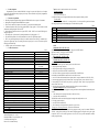
1
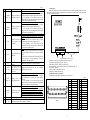
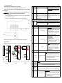
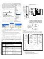
Commands loading to the controller’s memory – light both LED indicators.
The SMSD-822 controller turns to this mode from the standby mode as receives the command “LD”. In the
commands loading mode the controller accepts the executing commands only (table 7). After arriving the
command “ED” the controller record all received executing commands to the memory and turns to the standby
mode.
Reading commands from the controller –light both LED indicators.
The SMSD-822 controller turns to this mode from the standby mode. The sequence of executing commands from
the controller memory transfers to the computer as the controller receives the command “RD”. After the
commands transferred the controller turns back to the standby mode.
Temporary stop mode –blink both LED indicators.
The SMSD-822 controller turns to this submode during program executing as receives the signal «EN». The
controller suspends program executing while the signal is active. As the signal turns to inactive the controller
resumes the program executing.
10. Delivery in complete sets
The stepper motor controller SMSD-822
1 pcs.
SMC_Program can be delivered on a CD or by e-mail
1 pcs.
Manual SMSD.822.000
1 pcs.
Switch (Hall effect) SM8-31010NA – as an option, extra cost, on a request
1 pcs.
11. Warranty
Any repair or modifications are performed by the manufacturer or an authorized company.
The manufacturer guarantees the failure-free operation of the controller for 12 months since date of sale when the
operation conditions are satisfied – section 3.
The manufacturer sales department address:
Smart Motor Devices OÜ,
Tallinn Science Park Tehnopol, Mäealuse st. 4, Tallinn 12618, Estonia,
Phone: + 372 6559914,
e-mail: [email protected]
url: http://www.stepmotor.biz
SMART MOTOR DEVICES
http://www.stepmotor.biz
PROGRAMMABLE STEP MOTOR
CONTROLLER SMSD-822
Manual
SMSD.822.001
Date of sale:
2014
11
1.
Product designation
Programmable step motor controller SMSD-822 is designed to operate with hybrid two or four-phase
stepper motor with maximum current per phase up to 8.0 Amp. Three control modes are provided: programmable,
manual and simple driver.
2.
Functions and possibilities
Recording the operation algorithm from a computer to EEPROM of the unit as a sequence of commands.
Reading the saved algorithm from the EEPROM to a computer.
The unit can be controlled by computer (“direct control”) or can operate in a standalone mode.
In the manual mode: the unit receives analog signal “SPEED” (voltage signal 0 – 5VDC, internal or external
potentiometer) and digital signals “DIR” and “EN”.
In the simple driver mode: the unit receives signals “STEP”, “DIR” – 0VDC low level and 24VDC high level,
and digital signal “EN”.
The tracking mode - position control by internal potentiometer or by analog signal 0…5V.
For synchronized operation of several units and other devices there are 4 digital inputs/outputs/
There is zero positioning function provided (only in controller mode): start zero search by a command or by a
signal on the digital input. Stop zero searching movement as input signal is received. The function provides
homing by an individual input.
If “Enable” signal is active motor motion is stopped.
3.
Technical characteristic
Table 1
Common characteristic:
Number of controlled stepper motors
Maximum output current per phase, Amp
Minimum output current per phase, Amp
Microstepping modes
Pulse frequency in programmable and manual modes, Hz
Voltage input
Dimensions with connectors, mm
Inputs DIR, STEP
High voltage level, VDC
Low voltage level, VDC
Input resistance, kOhm, no less
Digital inputs EN, START, RESET, HOME, “0” and IO1, IO2, IO3, IO4 in
input mode:
Contact to COM
High voltage level of logic zero, VDC
Input voltage on open contacts, VDC
Input current on closed contacts, no more, mAmp
IO1, IO2, IO3, IO4 in output mode:
Signal type
Maximum voltage on output, VDC
Maximum load current, mAmp
Analog input:
Maximum current of analog input when input voltage is 5VDC, Amp
Communication interface – USB, virtual COM RS232:
baud
bits
parity
stop bit
Environmental Conditions:
Ambient Temperature: (-25…+40)°C
Humidity: 90%RH or less upon condition +25°C
Condensation and freezing: none.
Pressure: 650…800 mm of mercury
1
1
8.0
5.5
1/2; 1/4; 1/8; 1/16; 1/128; 1/256
1 – 10000
110 – 220 VAC
70 – 200 VDC
190x157x73
3.6 – 24
0 – 0.8
1.0
0.5
5
4.5
Open collector
24
20
10
9600
8
even
1
1
In “direct control” controller checks the value of acceleration:
The motor is stopped:
if while starting motion
(
)
< 0 or
= 0,
acceleration and start speed will be ignored and the motor will start operation with the speed SD
The motor rotates:
)
< 0, where
– current speed or
= 0, acceleration will be ignored and the motor
if (
will change its speed stepwise and remaining steps will be done with the speed SD.
Table 8
Reply
Description
E10*
The command successfully accepted
E12*
Interrupting or command execution by sending another command
E14*
Program executing completed
E15*
Communication Error (check port parameters)
E16*
Command error (check controller mode or ASCII code of the command)
E19 *
Command data error (check command data – integer, in allowed range, see table 6)
9. LED
Manual mode (SW1 – OFF, SW2 – ON)
The SMSD-822 is powered, step motor is stopped – light green color LED indicator.
Step motor is rotating – blink green color LED indicator.
EN signal is active – blink both LED indicators.
Driver mode (SW1 – ON, SW2 – OFF)
Light green color indicator.
Controller mode (SW1 – ON, SW2 – ON)
Standby mode – red color LED indicator.
The SMSD-822 controller goes to the standby mode in one of the next cases:
After program executing completed;
After program executing was stopped by command «ST1».
After power on (if microswitches SW1=On and SW2=On);
After “Reset” button or input activated (if microswitches SW1=On and SW2=On).
In the standby mode the SMSD-822 controller wait for one of the next event:
Arrival one of the control commands from a computer (table 6, accepted commands are «LD», «RD», «ST»);
Start executing program by pressing the button “Start” or input signal “Start” (connect “Start” and “Com”);
Start searching for a limit switch (zero position) by pressing the “Home” button or input signal “Home”
(connect “Home” and “Com”);
Turn to the other operation mode: manual or simple driver modes (see section 6 and table 6).
Program executing mode – blink red color LED indicator.
The SMSD-822 controller turns to the program executing mode and start motion algorithm from the standby mode
in case of:
“Start” button pressed or input activated (connect “Start” and “Com”);
Arrival the control command «ST»;
The SMSD-822 controller turns back from program executing to the standby mode in case of:
Executing program completed;
Arrival the control command «ST»;
“Reset” button pressed or input activated (connect “Reset” and “Com”).
Waiting for an external signal submode – blink red color LED indicator.
The SMSD-822 controller turns to this submode during program executing, as per the command “WHddd” or
“WLddd” – waiting for an external signal. The controller suspends program executing till receiving active signal
to input IO1, IO2, IO3 or IO4. As the signal arrives to IO1, IO2, Io3, IO4 (as per the command) the controller
resumes program executing.
10
Command
21
MHddd
(ddd=1…4)
22
MLddd
(ddd=1…4)
23
HM
24
SPddd
25
LL
26
JPddd
(1…255)
27
WLddd
(ddd=1…4)
28
WHddd
(1…4)
29
SCddd
(1…100)
Table 7
«Direct control»
Continuous movement, till signal IOddd is removed:
- if this command is received when the motor is stopped,
Indefinite movement, till continuous motion will begin till signal IOddd is removed;
- if this command is received while driving, from this
signal IOddd is removed
moment the motor will start continuous movement with the
current speed till signal IOddd is removed.
Continuous movement, till signal IOddd is set:
- if this command is received when the motor is stopped,
Indefinite movement, till continuous motion will begin till signal IOddd is set;
- if this command is received while driving, from this
signal IOddd is set
moment the motor will start continuous movement with the
current speed till signal IOddd is set.
IO1, IO2, IO3, IO4 are used as inputs
Continuous movement, till signal to input “0” (zero limit
switch)
Indefinite movement, till - if this command is received when the motor is stopped,
signal to input “0” (zero continuous motion will begin till signal to input “0”;
- if this command is received while driving from this
limit switch)
moment the motor will start continuous movement with the
current speed till signal to input “0”;
Pause: min 1ms – max 10000000ms
After receiving this command the motor will stop and wait
for ddd ms and then will continue to execute the remaining
Pause for ddddd ms, m =
steps.
100000000
If in pause time the commands MV, MVddd, MH, ML, HM
a received, they are executed immediately and previous
command is considered complete
Set
label
for
cycle
Set label for cycle operation – for program in buffer
operation
Repeat from label ddd
times,
=255. Set 2 Repeat from label ddd times, max 255. Set 2 commands
commands JPddd to create JPddd to create endless cycle
endless cycle.
Indefinite pause, wait removing signal IOddd
- if this command is received when the motor is stopped,
next command will be executed after signal IOddd is
Indefinite pause,
wait
removed;
removing signal IOddd
- if this command is received while driving, from this
moment the motor is stopped waiting removing signal IOddd
the previous command is considered complete
Indefinite pause, wait for a signal to input IN2
- if this command is received when the motor is stopped, next
Indefinite pause, wait for a command will be executed after signal on the input IOddd;
signal to input IOddd
- if this command is received while driving, from this moment
the motor is stopped waiting for a signal to input IOddd, the
previous command is considered complete
IO1, IO2, IO3, IO4 are used as inputs
This command is accessible only in the tracking mode, and gives possibility to set the scale
– the diapason of movement. The diapason = ddd•2000.
Standalone mode
9
4. Construction
SMSD-822 is designed as a circuit plate with electronic elements, installed on a heat sink plate and covered
with a metal case. Besides electronic components, there are indicating and control elements, connection terminals
and connectors on the board (img. 1).
Img.1. SMSD-822 controller scheme
Terminal screws for step motor windings (2) and power supply (1);
Plug for input/output signals connection – 25pins (3);
Control buttons “START”, “RESET”, and “HOME” (4);
Internal potentiometer for speed adjusting and for tuning: “SPEED/TUNING” (5);
Switches SW1 – SW8 (6)
LEDs for indication of the controller status (7).
USB plug for a computer connection (8).
All inputs of the unit are opto-isolated.
The numeration of input/output signals plug pins is shown in table 2.
Table 2
View from the connector on the body of the SMSD-822
controller
2
1
2
3
4
5
6
7
8
9
10
11
12
13
Signal
PUL
DIR
START
HOME
RESET
«0»
IO1
IO2
IO3
IO4
COM
SPEED/Position
+5V
14
15
16
17
18
19
20
21
22
23
24
25
Signal
PUL
DIR
EN
COM
COM
COM
COM
COM
COM
COM
COM
COM
5.
Assembly and connection
Please, learn this manual carefully before connection and assembly.
Please, wire just when power is off. Do not attempt to change wiring while the power is on.
Please, provide a reliable contact in connection terminals. During wiring, please, observe the polarity
and wire management.
ATTENTION: Power supply of the controller is dangerous for human’s health and life. It is
necessary to observe rules of electro technical safety! You need to ground the controller!
Assembly and connection order:
1.
Connect the SMSD-822 controller with stepper motor, switches and electric power supplier according
to one of schemes shown in images 2 – 8.
2.
Connect if it is necessary the SMSD-822 controller to a computer by an interface USB cable.
Command
5
9
10
11
Img.2. An example of scheme of power supply connection
If you use the DC power supply – connect it to N, L terminals; the polarity is not important.
12
Logic signal source
(high voltage level 24VDC)
Connection schemes
The connection examples are shown in the images 3 – 8. The switch connection example is shown in the
image 9.
13
14
15
Img. 3. Driver mode connection
example
Img. 4. Manual mode connection
example
Img.5. Tracking mode connection
example
16
17
18
19
3
RB
-
ED
Complete
executing
commands
sequence. After accepting this command
the controller records all transferred
commands into the memory and turns to
the standby mode.
7
8
Standalone mode
Table 7
«Direct control»
Read the command sequence from the
operational buffer.
If this command is received while driving, the
motor is stopped and turned off.
Complete executing commands sequence. After
accepting this command the controller record all
commands to operational buffer and turns to the
standby mode
Set the address pointer in 0
Begin - start a new algorithm, the Begin - start a new algorithm in the buffer, the
previous sequence is cleared.
previous sequence is cleared.
EN
Set “enable” - turn on the motor
DS
Set “disable” - turn off the motor
Forward motion
- if the motor is stopped, the start of the motion
will be in this direction;
DL
Forward motion
- if this command was received while driving,
the remaining steps are processed in the
direction according this command
Backward motion
- if the motor is stopped, the start of the motion
will be in this direction;
DR
Backward motion
- if this command was received while driving,
the remaining steps are processed in the
direction according this command
Reverse
- if the motor is stopped, the start of the motion
will be carried out in the opposite direction;
RS
Reverse
- if this command was received while driving,
the remaining steps are processed in the
opposite direction
1
AL(-)ddd
Acceleration ddd: min = -1000, max =1000
Speed:
- if the motor is stopped the start of the motion will be
carried out with this speed; if acceleration is used this
SDddd
Speed ddddd, max = 10000
command sets the final speed; if there is no acceleration
(1 to 10000)
steps/sec
this speed will be used as start speed;
- if this command was received while driving, the
remaining steps are processed with this speed
SSddd
Start speed: This command is used only for starting motion and only when acceleration is
used (AL 0)
(1 to 2000)
SFddd
Set the flag in output IOddd. IOddd is used as output.
(ddd=1…4)
Remove the flag in output IOddd. IOddd is used as output. If one of the signals IOddd has
CFddd
been used as output, and then it is going to be used as input, this command must be set
(ddd=1…4)
before.
Continuous motion
- if the motor is stopped, this command starts perpetual
motion;
MV
Continuous movement
- if this command was received while driving, continuous
motion with current speed begins
BG
8
If the program is in the “simple control mode” - input motor
operation parameters (steps number, speed, acceleration, direction)
and press the button “write” to record parameters to the controller and
press the button “start” to start motion according to the recorded
command sequence. Or press the button “Write and start” to record
new parameters and start motion at the moment.
If the program is in the programming control mode add to the
command list:
Controller mode connection examples
Home
4
Reset
5
«0»
6
EN
16
17...25
DIR
2
DIR
15
1kOhm
Img. 6. Controller mode
connection example
Img. 11
Img 12
img 14
img 13
When “Direct control” is used in the “Programming control mode” it is necessary to check box “Direct
control” and commands “Start loading”, “End loading” are not used. Command is executed as soon as it is written
in Command window.
Saving execute program with other terminal program with RS-232 communication function
Set the port number (check in the windows device manager, image 11), set port parameters according to the
table 1. Input required commands sequence using the ASCII codes (table 7, 8; section 8).
8. Commands
Commands in the programmable mode should be byte-serial (character-serial) transferred. Every command
should be completed with the ending character “*”. The ending character “\” instead of “*” cancels previous bytes
transfer (whole string). There is the commands list in the table 7. The SMSD-822 controller receives and checks
every command after receiving the ending character “*”. Controller sends to the communication port a reply after
receiving every command (successful or error command). All possible controller replies are presented in the
table8.
Table 7
Command
Standalone mode
«Direct control»
Start loading to the controller – after the
1
LD
command controller is in the loading mode.
Read the command sequence from the
2
RD
controller memory.
Start or stop the commands sequence executing
Start if the controller in the After receiving this command, the motor will
3
ST
programmable standby mode, stop if the stop immediately, the previous command is
considered complete
commands sequence is executing.
Start loading to the operational buffer.
4
LB
If this command is received while driving, the
motor is stopped and turned off.
7
3
COM
1) «Start loading to the coordinate 1»
;
2) Add commands to assemble the operation algorithm;
3) «End loading»
.
4) Press the button «send» under the command list.
Commands list and description are in the section 8.
“Commands”, and in the SMC_Program manual.
After the commands sequence (operation algorithm) is recorded
into the controller there are two possibilities: to continue control by
the SMC_Program or to use the controller in standalone mode. To
start program executing in the standalone mode press the “Start”
button or contact “Start” and “GND” at the controller frame.
Start
Img. 7. IO1, IO2, IO3, IO4 inputs
connection mode
Img. 8. IO1, IO2, IO3, IO4 outputs
connection mode
It is unacceptable to use one of the signals as input and output at the
same time. If it was used as output and then it will be used as input it is
necessary to turn the flag off with the CFddd command (look the
paragraph 8).
Img.9. NPN switch connection example
Motor connection
The SMSD-822 controller provides operation with 2 or 4-phase stepper motors, 4, 6 or 8 wires. Winding
connection examples are in the table 3. Connect step motor wires to A+, A-, B+ and B- terminals of SMSD-822.
Table 3
Scheme 1
Scheme 2
Scheme 3
8 wires stepmotor connection (4 phases):
Scheme 1 – serial connection;
Scheme 2 – parallel connection.
6 wires stepmotor connection (2 phases with midpoint taps):
Scheme 3;
4 wires stepmotor connection (2 phases without midpoint taps):
Scheme 4 .
6.
Before starting
1.
Make sure the power supply is turned off.
2.
Make assembly and connection according to paragraph 5.
Chose the suitable current and set microsteps SW7, SW8 according to table 4.
4
Scheme 4
Current, Amp
5.5
OFF
SW7
3.
6.2
ON
contact EN-16 contact on COM – 17…25 contact) - power is removed from the motor windings. Inputs PUL and
DIR are bidirectional, so the polarity of connected signals is not important.
Table 4
8.0
ON
6.5
OFF
OFF
OFF
ON
ON
SW8
Chose suitable microstepping mode and set micro switches SW3, SW4, SW5 according to table 5.
Table 5
Microstepping mode
1/2
1/4
1/8
SW3
ON
OFF
ON
SW4
OFF
ON
ON
1/16
1/32
1/64
1/128
1/256
OFF
ON
OFF
ON
OFF
OFF
OFF
ON
ON
OFF
OFF
OFF
OFF
ON
ON
ON
ON
OFF
SW5
Set the switch SW6 for automatic reduction of holding current: SW6 – ON 100%; SW6 – OFF
70%.
5.
Chose suitable operation mode and set micro switches SW1, SW2 according to the table 6.
There are three operation modes: controller, driver and manual. Also “Tuning” mode is provided for setting
of the unit with the connected motor. Before starting the operation with the connected motor at the first time it is
necessary to use “Tuning” to low vibration and resonance effect – look paragraph 7.
Table 6
Operation mode
SW1
SW2
Controller
ON
ON
Manual (also entrance to the tracking mode)
OFF
ON
Driver
ON
OFF
“Tuning”
OFF
OFF
If the unit is powered, the new operation mode is applied after RESET (by button or input signal).
6.
Check wiring once again and turn on the power supply.
4.
7.
Operation modes
7.1. Tuning
When step motor is connected to SMSD-822 controller at first time it is necessary to make “Tuning” (SW1
and SW2 – OFF) to low vibration and resonance. Phase current is set according to table 4; microctepping mode is
set according to the table 5. When the controller is powered motor starts to rotate. Set the potentiometer
“SPEED/TUNING” so that the motor works without any vibrations and noise. When the successful result has
been reached press HOME button – the controller will remember this setting. If stepmotor connected to the
controller is changed it is necessary to make tuning again for new model of the motor.
7.2. Manual mode
The speed is adjusted by the internal potentiometer SPEED or external potentiometer or analog signal 05VDC. Speed value is saved when leaving this mode, and it is restored when re-entry this mode.
When the external potentiometer is used, it is necessary to set the minimum speed with internal
potentiometer SPEED (fully clockwise position) and connect external potentiometer to terminals +5V / SPEED /
COM (img.2), or connect contacts of analog signal source to terminals SPEED / COM (maximum current of
analog input is 10 Amp when Uinput = 5V).
To change direction it is necessary to set signal DIR: high level – one direction; low level – another
direction.
To start motion you need to push START button or use START/COM terminals. To stop motion you need to
push START button once more or RESET button, in this case power is removed from the motor windings.
If EN signal is used: high level – motor is stopped, low level – motor continues motion.
When internal potentiometer SPEED is used two-zone speed control is provided. By default, potentiometer
controls speed in diapason from 1step/sec up to 1000step/sec – accurate speed setting. If after changing speed
potentiometer is moved to speed 1step/sec – coarse speed setting is turned on, now potentiometer controls speed
in diapason from 1step/sec up to 20000step/sec.
7.3. Driver mode
Connection example is shown in the image 3. One step (or microstep) executes as front edge of the voltage pulse
on the “PUL” input (1, 14 contacts of the connector). Direction switches by changing voltage level on the “DIR”
input (2, 15 contacts of the connector). The motor can be stopped by the active signal on the “EN” input (clean
5
Img.10. STEP and DIR input signals
7.4. Tracking mode
This mode gives possibility to control the position by the internal potentiometer, or external potentiometer, or
by the analog signal 0…5V. To select this mode it is necessary to set driver mode (SW1 – ON, SW2 – OFF).
After that you need to press button RESET, while holding it, press START button. Then release RESET button,
and hold START button until red LED will stop lighting. When the controller enters this mode it takes the current
position of potentiometer or control voltage (at the inputs COM-11, Position-12) as “zero coordinate”. If you need
to rotate motor in both sides, it is accessible to set the potentiometer in the middle position, or set 2.5V of control
voltage before entering this mode. Increasing the voltage corresponds to the rotation of the motor in one direction;
decreasing the voltage corresponds to the rotation of the motor in other direction.
If You connect the controller to the PC you can set start speed (command SSddd*), acceleration (ALddd*);
working speed (SDddd*). You need just send these commands to the controller. Also scale can be set by the
command SCddd*. All these commands are saved in EEPROM of the controller, so further connection to the PC
is not necessary.
Scale setting example: Scale 1000 (SC1000* is used). Analog voltage 2.5V is used as “zero coordinate”.
Changing voltage from 2.5V to 5V will correspond to 500steps (microsteps) of motor in one direction, and
changing voltage from 2.5V to 0V will correspond to 500steps (microsteps) of motor in another direction.
7.5. Controller mode
There are two possible variants of operation in this mode:
Direct control: it gives the possibility to control the step motor in “real time” mode;
Stand alone mode: for a standalone operation the executing program should be saved via
USB (virtual RS-232), after that the USB cable can be disconnected.
For virtual RS-232 communication the special driver USB-RS-232 should be installed to the computer.
Please, save on computer hard drive the installation pack CP210x_VCP_Win2K_XP_S2K3.zip. Unpack and
execute the exe file. Please, follow the instructions during the installation progress. As a result when the controller
is connected to the PC, the additional program COM-port appears (CP2102 USB to UART Bridge Controller).
The availability and the number of new port can be checked in windows device manager (Windows XP: On
the desktop right-click on My Computer and click Properties or open the Control Panel and double-click the
System icon. In the System Properties window click the Hardware tab. In the Hardware tab click the Device
Manager button) – image 11. This COM-port should be used for communication with SMSD-822 controller. The
port properties should be set in a terminal program according to the table 1. As a terminal program SMC_Program
or some other software (software should provide RS-232 ASCII communication) can be used. The program is
available and supplied with the SMSD-822 controller.
SMC_Program
The program should be copied to the hard drive of the computer. Unpack the program pack. SMC_Program
doesn’t require registration and installation. The write read operations should be allowed in the program folder
(carefully check for windows vista and windows 7).
It is necessary to set port properties in SMC_Program. Menu “Port settings” > «Chose port» (image 12)
chose the connected port number and press “Ok” (image 13).In the “simple control panel window” check the box
1, (coordinate 1 – img.14).
6