1
POWERTEK
MC-140 Multifunction Calibrator
Content
Basic Information ................................................................................................................. 3
Preparation for operation ..................................................................................................... 5
Inspecting package contents, selecting the installation location....................................................... 5
Power-on ................................................................................................................................................... 5
Warm-up time .......................................................................................................................................... 5
Replacement of fuse................................................................................................................................. 6
Safety precautions.................................................................................................................................... 6
Description of controls .......................................................................................................... 7
Front panel................................................................................................................................................ 7
Rear panel ............................................................................................................................................... 13
Control of the calibrator...................................................................................................... 14
Selection of function .............................................................................................................................. 14
Setting the value of output signal ........................................................................................................ 14
Setting relative deviation ...................................................................................................................... 16
Change of value by factor of ten.......................................................................................................... 17
Connection / disconnection of output terminals ............................................................................... 17
Setting the frequency............................................................................................................................. 18
Generation of calibrated voltage ......................................................................................................... 19
Generation of calibrated current ........................................................................................................ 21
Generation of non-harmonic shapes................................................................................................... 22
Simulation of resistance and capacitance .......................................................................................... 23
Generation of electric power and energy ........................................................................................... 26
Generation of frequency ....................................................................................................................... 31
Simulation of temperature sensors ..................................................................................................... 34
Multimeter........................................................................................................................... 38
Basic menu .............................................................................................................................................. 38
Function selection .................................................................................................................................. 39
Setting the measurement range ........................................................................................................... 39
Units of measurement ........................................................................................................................... 40
Use of calculation formula.................................................................................................................... 41
Setting function parameters................................................................................................................. 41
Start of measurement ............................................................................................................................ 42
Zero function .......................................................................................................................................... 42
Simultaneous functions ......................................................................................................................... 44
User Manual v35
1
MC-140 Multifunction Calibrator
POWERTEK
Tester................................................................................................................................... 46
Basic menu.............................................................................................................................................. 46
Execution of test program.................................................................................................................... 46
Programming the test ........................................................................................................................... 47
Setting the type of signals and the number of steps............................................................................................48
Setting the numeric values of the test..................................................................................................................48
Setting the relays...................................................................................................................................................49
Setup menu ......................................................................................................................... 49
Calibration mode................................................................................................................. 54
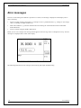
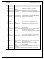
Error messages.................................................................................................................... 72
Functional description of the calibrator.............................................................................. 74
Calibrator’s maintenance.................................................................................................... 80
Performance verification test .............................................................................................. 82
System control ..................................................................................................................... 90
IEEE-488 bus properties ...................................................................................................................... 90
RS232 bus properties ............................................................................................................................ 90
Command syntax ................................................................................................................................... 91
Standard Status Data Structures ...................................................................................................... 105
Examples of use ................................................................................................................ 108
Calibration of measurement instruments........................................................................................ 108
Multimeters .........................................................................................................................................................108
Powermeters ........................................................................................................................................................110
Counters and oscilloscopes ................................................................................................................................112
Thermometers .....................................................................................................................................................112
Measurement........................................................................................................................................ 113
Voltage, current and frequency ..........................................................................................................................113
Measurement of resistance or temperature using resistance temperature sensors..........................................114
Measurement of temperature using thermocouples..........................................................................................115
Strain gauge sensors for non-electrical values..................................................................................................115
Testing of regulation and measurement sets and evaluation units.............................................. 117
Use of Opt. 140-41 cable adapter ......................................................................................................................117
Use of Option 40/60 cable adapter ....................................................................................................................118
Use of Option 70 .................................................................................................................................................118
Examples of tests ................................................................................................................................................118
Testing .................................................................................................................................................................120
Specification...................................................................................................................... 121
Accessories ........................................................................................................................ 128
2
User Manual
POWERTEK
MC-140 Multifunction Calibrator
Basic Information
MC-140 Multifunction Calibrator is a multifunction calibrator-tester, to be used primarily as a standard
for calibration laboratories. It can be used for calibration of any measuring instrument which measures voltage,
current, resistance, capacitance and frequency. It generates fixed non-harmonic signals to allow calibration
of measuring instruments using signals with non-zero harmonic distortion. Frequency, amplitude and duty cycle
of output signal can be adjusted. MC-140 Multifunction Calibrator is also suitable for basic calibration
of oscilloscopes.
The calibrator includes a function which simulates resistance and thermocouple temperature sensors
and a built-in multimeter, which can be used simultaneously. Transducers of various types, regulators and
sensing units can be therefore checked without the need for additional measuring instruments.
Programmable functions of the calibrator, when used as a tester, include programming of a 10-step testing
procedure, which completes automatically and displays a PASS/FAIL information in the end. This feature is
linked to an independent relay output, which allows the control of other equipment.
Basic features of the calibrator include: generation of calibrated DC and AC voltage in the range of 0
µV to 1000 V, DC and AC current in the range of 0 µA to 20 A (50 µA to 1000 A when using a 50-turn coil).
Maximum precision of the calibrator is 0.0035 % for DC voltage, 0.03 % for AC voltage, 0.013 % for DC
current and 0.055 % for AC current. Maximum frequency range is 20 Hz to 50 kHz. The calibrator can generate
periodic non-harmonic signal with defined duty cycle. This facilitates especially the checks of multimeters and
their accuracy when measuring non-harmonic DC signals.
The calibrator can also simulate a resistance or capacitance. Resistance range is 0 Ω to 50 MΩ;
capacitance range is 1 nF to 50 µF, the accuracy suits the calibration of common multimeters. Basic accuracy
of resistance ranges is 0.03 %. Basic accuracy of capacitance ranges is 0.5 %. The resistance can be used with
AC signals up to 300 Hz to 1 kHz, depending on set-up value.
Frequency ranges of the calibrator can generate a squarewave signal with definable and calibrated duty
cycle and amplitude in the 1 mV to 10 V range and 0 to 10 kHz frequency range. Moreover, squarewave signal
with very steep rising edge can be generated up to 20 MHz. Frequency ranges can be used to calibrate the
corresponding frequency ranges of multimeters, as well as to calibrate the input sensitivity and time bases of
oscilloscopes.
Powermeter mode can be used to calibrate DC and AC single phase powermeters and energy meters.
Voltage range is up to 240 V and current range is up to 10 A, power factor range is -1 to +1 and the resolution is
1 % in the 40 Hz to 400 Hz frequency range. The voltage output can supply loads up to 30 mA, which allows the
calibration of mechanical powermeters.
Simulation of temperature sensors is yet another feature which can be used to calibrate thermometers
and heat sensing units. The calibrator allows the simulation of all common Pt and Ni resistance sensors and R, S,
B, J, T, E, K, N type thermocouples. Compensation of cold junction of thermocouple is achieved by entering
the respective temperature using the calibrator’s keyboard. The accuracy of simulated temperature sensors
depends on the value and type of sensor and ranges from 0.04 oC to 0.5 oC for resistance sensors and from
0.4 oC to 4.3 oC for thermocouples.
Internal multimeter with 20 mA, 20 mV, 200 mV and 10 V basic ranges and 0.01 % accuracy can be
used to measure normalized signals coming from transducers, external thermocouples or resistance sensors or to
measure pressure and force using strain gauge sensors.
The calibrator includes many other features which facilitate easy use. For example relative deviation from set
value of the output, currently displayed uncertainty of the output signal, calibration and testing procedures etc.
The concept of calibrator control and indication of its status is based on flat luminiscent display, which provides
all necessary information. The calibrator is controlled by opening menus on the display and selection from
menus. Frequently used functions are assigned direct-control keys. The calibrator comes with standard GPIB bus
and RS-232 serial line, which allow the calibrator to be controlled from a PC.
The calibrator can easily fit within calibration systems featuring MBASE/WinQbase software support.
User Manual v35
3
MC-140 Multifunction Calibrator
POWERTEK
ATTENTION !
The calibrator generates life-threatening high voltage.
The calibrator can only be used in line with this
Manual.
4
User Manual
POWERTEK
MC-140 Multifunction Calibrator
Preparation for operation
Inspecting package contents, selecting the installation location
Basic package includes the following items:
•
Multifunction calibrator
•
Power cord
•
Spare fuse T4L250/T, T8L250/T
•
Operation manual.
•
Test report
•
Test cable 1000V/20 A 2 pcs
•
Cable adapter Option 40
•
Cable adapter Option 60
•
Cable adapter Option 70
•
RS 232 cable
The calibrator should be powered by 230/115 V – 50/60 Hz mains. It is a laboratory instrument whose
parameters are guaranteed at 23±2 oC. Before powering on the instruments, place it on a level surface. Do not
cover the vents at the bottom side and the fan opening at the rear panel.
Power-on
•
Before connecting the calibrator to the mains, check the position of the mains voltage selector located at the
rear panel.
•
Plug one end of the power cord into the connector located at the rear panel and connect the other end of the
power cord into a wall outlet.
•
Switch on the mains switch located at the rear panel. Flat display is lit.
•
•
The calibrator performs internal hardware checks for 5 seconds.
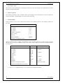
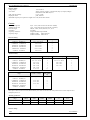
After the tests conclude, the calibrator resets to its reference state, i.e. the following parameters are set:
Function
DC voltage
Range
20 V
Set value
10 V
Output terminals
OFF
GPIB address of the calibrator is factory-preset to 2. This value is valid until the user changes it.
Note. The calibrator resets to its reference status in case of power switching off and reconnection.
Warm-up time
The calibrator works after it is switched on and the initial checks complete. Specified parameters are only
guaranteed after the instrument warms up for 60 minutes. During this period, the instrument cannot be calibrated.
The display shows “cannot access the calibration” message if calibration is attempted during this period.
User Manual v35
5
MC-140 Multifunction Calibrator
POWERTEK
Replacement of fuse
The calibrator includes a fuse located in the mains connector at the rear panel. Replace the fuse as follows:
•
Switch off the calibrator
•
Remove the end of power cord from the mains connector at the rear panel.
•
Insert the blade of a flat screwdriver into the opening cut in the mains voltage selector and pull out the fuse
holder.
•
Remove the fuse and replace it with new fuse of the same rating.
Safety precautions
The instrument has been designed in Safety Class I according to EN 61010-1. The design reflects the
requirements of A2 amendment of the standard.
Safety is ensured by the design and by the use of specific component types.
The manufacturer is not liable for the damage caused by modification of the construction or replacement of parts
with non-original ones.
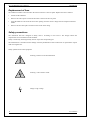
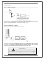
Safety symbols used on the equipment
Warning, reference to the documentation
Warning - risk of electric shock
Danger - high voltage
6
User Manual
POWERTEK
MC-140 Multifunction Calibrator
Description of controls
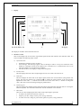
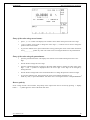
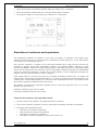
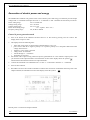
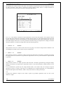
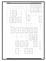
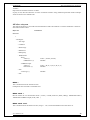
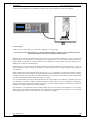
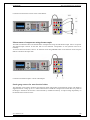
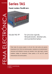
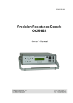
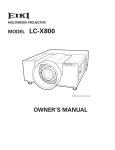
Front panel
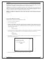
The front panel of the calibrator includes a flat luminiscent display, control buttons and output terminals. The
following picture shows the control part of the front panel.
3
1
1
2
5
4
6
7
Display buttons
There are five buttons below the display, whose meaning changes depending on the contents of the display.
These buttons usually call-up the MENU, allow range change, step, logging of values etc.
2
Cursor buttons
Using these buttons, the cursor can be controlled within allowed limits on the display. The keyboard includes
two buttons (<, >) which allow the cursor to be set to the required position at the display. The cursor can be
moved to the left or right. These buttons are usually used to step through the options and to move from one
option to another or between the menu levels. Numeric values can be set in some control modes as well. In these
cases, the buttons marked (∧, ∨) allow the user to increase or decrease the number at the cursor button.
The central button is used to confirm the selection (ENTER), or to SELECT from the menu.
3
Potentiometer
The potentiometer integrates several functions. By turning the knob to the left or right, the user can:
•
step through the options
User Manual v35
7
MC-140 Multifunction Calibrator
POWERTEK
enter numeric values
•
The function of the potentiometer can usually be performed by the cursor buttons. The central button is used to
confirm the selection (ENTER).
4
Numeric keyboard
The keyboard allows the entry of numeric values on the display. The central button is used to confirm the
selection (ENTER). CANCEL button can be used to cancel the entry.
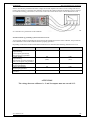
5
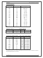
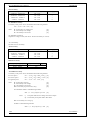
Function buttons
Function buttons can be used to call-up the functions of the calibrator directly. The following buttons are
provided:
function
button
DC voltage
AC voltage
DC current
AC current
resistance / capacitance
power / energy
frequency
internal multimeter
simulation of temperature sensors
U / DC
U / AC
I / DC
I / AC
R–C
P–E
F
METER
T
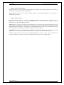
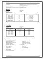
After the function mode is changed, the parameters of the respective function are restored. If the respective
function was never used, the calibrator resets to its reference values. Reference values for individual functions
are listed below.
*1
8
function
value
parameters
DC voltage
AC voltage
DC current
AC current
resistance
10V
10 V
100 mA
100 mA
100 kΩ
-f = 1000 Hz
-f = 1000 Hz
capacitance
1 µF
power
energy
frequency
multimeter
simulation of temperature sensors
cold junction temperature of TC sensors
100 W
f = 100 Hz *1
1000 Hz
10 V
100 oC
23 oC
U = 1 Vsym
DC voltage
Pt 100/1.385, ITS90
R
U = 100 V, I = 1 A, PF(power factor) = 1 LA, active power is displayed in Watts
User Manual
POWERTEK
6
MC-140 Multifunction Calibrator
Output / input terminals buttons
OUTPUT button is used to connect the output signal of the calibrator to the output terminals. The connection is
confirmed by red LED and a symbol at the display.
METER button can be used to connect the input terminals to the internal multimeter. The connection is
confirmed by green LED.
7
Output / input terminals
Output signal of the calibrator is connected to the output terminals. Current ranges are connected to +I / -I
terminals, frequency output is connected to FREQ terminal. All other functions (voltage, resistance,
capacitance) are connected to Hi / Lo terminals.
GND terminal is connected to the chassis of the calibrator. It is connected to the ground terminal of the mains
plug. Using the SETUP MENU of the calibrator, the output terminals of the calibrator can be grounded as well.
Grounding is done internally by connecting Lo and GND terminals using a relay. This circuit design is suitable
for most calibrations, when the object (multimeter) being calibrated is floating.
AUXILIARY connector creates input of internal multimeter. It includes a limited range of output signals of the
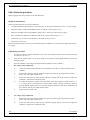
calibrator as well. The layout of individual pins and their meanings are listed in the following table.
Auxiliary connector can be used with one of cable adapters Opt. 40, 60, 70, Opt. 140-41. Calibrator can
recognize which type of adapter is connected and displays the information on front panel display.
User Manual v35
9
MC-140 Multifunction Calibrator
POWERTEK
pin
label
signal
Limitation
1
0V5MER
common terminal of multimetr power supply source
2
GND
ground (protection earth)
3
SIMLI
RC simulator output, current terminal Li
Umax.= 10Vpp, Imax.=40mA
4
SIMLU
RC simulator output, voltage terminal Lu
Umax.= 10Vpp, Imax.=40mA
5
GND
ground (protection earth)
6
L
common terminal of multimeter input
7
-U
low output terminal for DC voltage range
8
-I
low output terminal for DC current range
9
NG2
sort function output, contact 2 of sort relay
Umax.=50Vpp, Imax.=100 mA
10
PTLI
resistance temperature sensor input terminal Li
Umax.= 10Vpp. R<2 kΩ
11
PTLU
resistance temperature sensor input terminal Lu
Umax.= 10Vpp. R<2 kΩ
input terminal L on ranges 20, 200, 2000 mV
12
TEST1
identification terminal of actually used adapter
13
TEST3
identification terminal of actually used adapter
14
0V5MER
common terminal of multimeter power supply source
15
NC
not used
16
SIMHI
RC simulator output, current terminal Hi
Umax.= 10Vpp, Imax.=40mA
17
SIMHU
RC simulator output, voltage terminal Hu
Umax.= 10Vpp, Imax.=40mA
18
NC
not used
19
INP
multimeter input terminal for voltage/current ranges
Umax.=25 Vpp, Imax.=25 mA
20
+U
high output terminal for DC voltage range
Umax.=20 Vss
21
+I
high output terminal for DC current range
Imax.=25 mA
22
NG1
sort function output, contact 1 of relay
Umax.=50Vpp, Imax.=100 mA
23
PTHI
resistance temperature sensor input terminal Hi
Umax.= 10Vpp. R<2 kΩ
24
PTHU
resistance temperature sensor input terminal Hu
Umax.= 10Vpp. R<2 kΩ
input terminal H on ranges 20, 200, 2000 mV
25
TEST2
identification terminal of actually used adapter
TEST1
Functional inputs and outputs present at the connector can be best utilized using supplied cable adapters.
LCD display shows all information provided by the calibrator, e.g. set parameters of the signal, error messages,
setup information. The display is divided to several information sections.
10
User Manual
POWERTEK
8
MC-140 Multifunction Calibrator
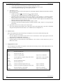
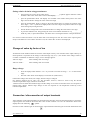
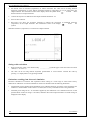
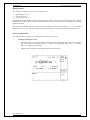
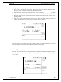
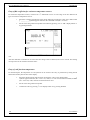
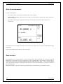
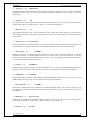
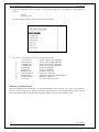
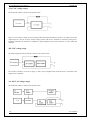
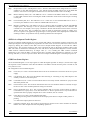
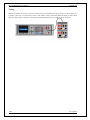
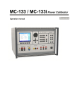
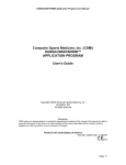
Display
1a 1b 1c 1d 1e 2a
3
2b 1g 1f
The display is divided to three horizontal sections:
1.
OUTPUT section
This section displays the set-up values of generated signals and the data related to the calibrator status. The
section includes the following types of data:
a)
Information line
•
•
•
designation of display section: OUTPUT
error messages. The messages appear when an attempt is made to set up an invalid state of the
calibrator, if analogue circuits of the calibrator are overloaded or if a communication error occurs
when the calibrator is controlled using GPIB bus.
real date and time, if its display is set-up in the setup menu.
b) Auxiliary data
This line displays the total value of output signal if a non-zero relative deviation is set.
c)
Main data
This line displays the main data of the output signal and the unit of measurement (using double size
signs). The line also includes two symbols (▼▲) to define the actual position of the cursor during
adjustment of the value. <, > buttons can be used to move the cursor and ∧, ∨ buttons to change the
value. (The value can be also changed using the potentiometer).
d) Monitoring line
This line displays the numbers entered using the numeric keyboard when the main data are set using the
numeric keyboard. The information allows the entered information to be checked.
e)
Minor data
There are two lines displaying the minor data of the output signal, especially:
•
•
•
set relative deviation from main set value in %
frequency (for DC voltage, current, power, energy functions)
set value of current, voltage or power factor (phase) for power, energy functions
User Manual v35
11
MC-140 Multifunction Calibrator
•
•
•
f)
POWERTEK
value of R0 resistance and the type of resistance temperature sensor
cold junction temperature of TC sensors and the selected type of TC sensor
value of amplitude and shape type for frequency function
Information section
The information section located in the right part of the display displays additional information related to
the selected function:
• symbol of connected
or disconnected
output terminals.
•
•
•
•
At the same time, a LED located above the OUTPUT button is lit.
information about remote/local control of the calibrator. If the calibrator is controlled remotely,
REM is displayed. If the calibrator is controlled locally using the keyboard, LOCAL is displayed.
information about the use of 50-turn coil (COIL x50) at the current output of the calibrator, if this
feature is turned on using the SETUP menu.
information about the type of connected cable adapter, if used
information about the grounding method of output terminals: GND I, GND U as set up using the
setup menu.
g) Information about the uncertainty of the output signal
This section displays the maximum error of the main value of the output signal. The value is calculated
using the main specification listed in the User’s Manual and it is displayed in %.
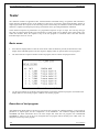
2.
INPUT section
This section displays the values measured by the multimeter. The section includes following data:
a) Main value of measured signal
This line displays the measured value and the unit of measurement. If the input signals exceed the
permitted range, OVERFLOW is displayed.
b) Designation of selected function of the multimeter
Symbolic display of selected function of the multimeter: V DC, mA DC, mV DC, R 4W, Freq, T TC, T
RTD, SGS, ACAL.
3.
Display buttons section
This line displays the symbolic descriptions which define the meaning of four related display buttons. The
respective meanings are as follows:
12
symbol
button function
note
x 10
increase set value 10 x
: 10
decrease set value 10 x
Shape
selection of signal shape
only for U, I, F functions
+/-
reversed polarity of output voltage and current
only for DC U, DC I functions
EXIT
move up one level
only for F, P-E functions
Calib.
enter the calibration menu
SETUP
enter the setup menu
TC type
selection of thermocouple sensor type
only for T function
RTD type
selection of resistance temperature sensor type
only for T function
f
enter the frequency of the signal
only for U, I function
MODE
select the unit of measurement
only for AC P-E function
User Manual
POWERTEK
MC-140 Multifunction Calibrator
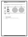
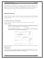
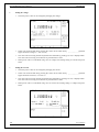
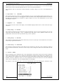
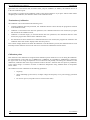
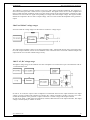
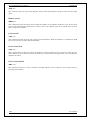
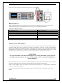
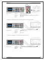
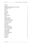
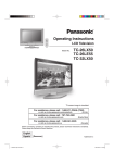
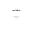
Rear panel
The rear panel of the calibrator includes ventilation holes, power cord socket with fuse, mains voltage selector,
mains switch, IEEE 488 connectors for connection to GPIB bus and type plate with serial number.
5
4
1
2
3
4
5
1
2
3
air inlet - forced ventilation
air outlet - forced ventilation
GPIB, RS-232 connectors
power cord socket with fuse, mains voltage selector, mains switch
type plate
User Manual v35
13
MC-140 Multifunction Calibrator
POWERTEK
Control of the calibrator
Selection of function
After the power is switched on and the initial checks complete, the calibrator resets to its reference status, i.e. DC
voltage output with set value of 10 V and output terminals disconnected. Internal multimeter is switched off. The
status of the calibrator can be changed using the buttons located at the front panel in one of the following ways:
1.
Change of function by pressing one of direct function buttons
After pressing one of the U, I, DC-AC, R-C, P-E, F, T, METER buttons, the calibrator switches to the desired
function mode and resets to the reference or to the most recently used parameter setting.
2.
Connection /disconnection of output terminals
After pressing the OUTPUT button, the output terminals of the calibrator are connected/disconnected.
3.
Connection /disconnection of multimeter
After pressing the INPUT button, the multimeter starts measuring the value present at the input terminals,
depending on the function mode of the multimeter. The measurement is only possible when any of Opt. 140-xx
adapters is connected to the AUXILIARY connector.
4.
Entry to the setup menu
After pressing the SETUP button, options of the SETUP MENU appear on the display and the display buttons
allow the entry to the calibration mode (CALIB) or entry to the mode when the calibrator is used as a tester
(TESTER). Previous function is restored by pressing of EXIT display button.
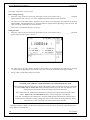
Setting the value of output signal
All function modes allow several methods of setting the main value of the output signal:
Entry of the value using numeric keyboard
14
•
use the numeric keyboard to select the desired value. After the first digit is entered, symbols of unit
of measurements are displayed above the display buttons. The monitor line displays the symbols
[ _ _ _ _ _ _ _ _ ].
•
the same entry can be started by pressing the central cursor button
•
after the entry is complete (the value is displayed on the monitor line), press the display button
below the desired unit of measurement (V, mV or µV in the example below)
•
the value is copied to the main display and the monitor line disappears.
User Manual
POWERTEK
MC-140 Multifunction Calibrator
Entry of the value using cursor buttons
•
press <, >, ∧ or ∨ button. The display now includes cursor marks which point to the active digit.
•
∧ and ∨ buttons can be used to change the active digit. <, > buttons can be used to change the
position of the cursor marks
•
to get to the default screen, press EXIT button or keep pressing the center cursor button until there
is no [ _ _ _ _ _ _ _ ] under any value. All values can be set using the buttons or the potentiometer.
Entry of the value using the potentiometer
•
press the potentiometer knob. The display now includes cursor marks which point to the active
digit
•
turn the knob to change the active digit
•
press the potentiometer knob to change to the mode which allows to change the value of the active
digit. ← and → symbols are displayed above the active digit. Active digit can be changed by
turning the knob.
•
turn the knob to change back to the mode which allows to change the position of the active digit.
•
to get to the default screen, keep pressing the center cursor button until there is no [ _ _ _ _ _ _ _ ]
under any value, or press EXIT button. All values can be set using the buttons or the potentiometer.
Reverse polarity
In DC voltage and DC current modes, the polarity of the output value can be reversed by pressing +/- display
button. “ – ” symbol appears in front of the main data value.
User Manual v35
15
MC-140 Multifunction Calibrator
POWERTEK
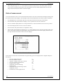
Setting relative deviation
All function modes of the calibrator except frequency mode allow a relative deviation of output value from the
main data to be set using a separate display. Relative deviation is displayed in the “minor data” section of the
display and is designated with “ Δ%= 00.0000 % ” symbol. The relative deviation can be entered using one of
the methods described above, e.g. using the numeric keyboard, cursor keys or the potentiometer.
Setting relative deviation using numeric keyboard
•
keep pressing the center cursor button until [ _ _ _ _ _ _ _ ] symbols appear under the relative
deviation value in the “minor data” section of the display
•
enter the desired deviation and confirm the value by pressing “ % ” display button or by pressing
ENTER on the numeric keyboard
•
the auxiliary line below the main data on the display displays the total value of output signal
including the unit of measurement
•
the value of the signal at output terminals is:
the value indicated by the main display + ∆ %.
Maximum relative deviation which can be entered is ± 30.000 %.
The deviation can be positive or negative. If negative deviation is desired, press the display button labeled +/-. If
positive deviation is then desired, press “ +/- ” button again. The polarity of the relative deviation can be
reversed using the cursor buttons or the potentiometer as well.
Setting relative deviation using cursor keys
16
•
keep pressing the center cursor button until [
deviation value
_ _ _ _ _ _ _ ] symbols appear under the relative
•
press <, >, ∧ or ∨ button. The display now includes cursor marks which point to the active digit
•
∧ and ∨ buttons can be used to change the active digit. <, > buttons can be used to change the
position of the cursor marks
•
to get to the default screen, keep pressing the center cursor button until there is no [ _ _ _ _ _ _ _ ]
under any value, or press EXIT button. All values can be set using the buttons or the
potentiometer..
User Manual
POWERTEK
MC-140 Multifunction Calibrator
Setting relative deviation using potentiometer
•
keep pressing the center cursor button until [ _ _ _ _ _ _ _ ] symbols appear under the relative
deviation value in the “minor data” section of the display
•
press the potentiometer knob. The display now includes cursor marks which point to the active
digit. Turn the knob to change the value of the active digit
•
press the potentiometer knob to change to the mode which allows to change the position of the
active digit. ← and → symbols are displayed above the active digit. The position of the active digit
can be changed by turning the knob.
•
turn the knob to change back to the mode which allows to change the value of the active digit
•
to get to the default screen, keep pressing the center cursor button until there is no [ _ _ _ _ _ _ _ ]
under any value, or press EXIT button. All values can be set using the buttons or the potentiometer.
If a non-zero relative deviation is set, the main data can be changed as well. The value of the output signal is
always recalculated. If a zero relative deviation is set, the “minor data” section is not displayed.
Change of value by factor of ten
All functions of the calibrator allow the increase of the output value by 10 or reduction of the output value by 10.
Such operation is equivalent to the change of internal range only in U, I, P-E modes. If the change results in
overflow or underflow of calibrator’s range, an error message appears:
Value too large !
if the resulting value is too large
Value too small !
if the resulting value is too small
Range change
•
Press the display button labeled “ x10 ” if you want to increase the range, “ :10 ” to decrease the
range.
•
The main value shown on the display is increased 10x (reduced 10x)
P-E function changes the current, not voltage, when the range is changed.
R-C function changes the set value 10x. The procedure, however, cannot be used to step the internal
resistance/capacitance ranges, which are not decimal.
T function also has other than decimal ranges and the change of set value 10x therefore does not correspond to
internal range change. Internal range change in this case depends on the temperature sensitivity of the
resistance/capacitance.
Connection / disconnection of output terminals
After switching on the output terminals are disconnected in all modes. Press the OUTPUT button to connect the
output signal to the terminals. Red LED above the OUTPUT button is lit and the information field on the
display shows the following
symbol .
Press the OUTPUT button again to disconnect the output terminals. Red LED goes off and the information field
User Manual v35
17
MC-140 Multifunction Calibrator
POWERTEK
on the display shows the following symbol .
During mode change, output terminals are always disconnected. Output terminals are disconnected also when
changing between voltage and current ranges or when changing between AC and DC ranges is performed.
If voltage over 100 V is set in the voltage mode, special algorithm must be followed to connect the output
terminals. The algorithm is described in the “Generation of calibrated voltage” chapter of this Manual.
Setting the frequency
Frequency can only be selected in AC voltage (ACU) mode, AC current (ACI) mode , power (P-E) mode and
frequency (f) mode. In each mode the frequency has a slightly different meaning and the frequency is therefore
set in a different manner.
AC voltage (ACU), AC current (ACI)
Set value of frequency is included in the “minor data” section of the display in ACU, ACI, P-E modes.
Frequency change
•
First select the AC voltage or AC current mode by pressing U (I), AC buttons or selecting the P-E
mode using the display. Frequency value “f = xxx.xx Hz” appears in the “minor data” section of
the display. “ f “ symbol is displayed above one of the display buttons.
•
After “ f ” display button is pressed, [ _ _ _ _ _ _ _ ] symbols appear below the frequency value.
Numeric keyboard can be used to enter the desired value. Press “ Hz ” or “ kHz ” to confirm the
value. The value can be set using the buttons or the potentiometer.
If too large or too small value is entered, the calibrator displays the maximum (minimum) value which is allowed
for the selected function.
Frequency (F)
Set value of frequency is the main data on the display and the main parameter of the signal. Main data can be set
by direct entry using the numeric keyboard, potentiometer or by changing the digit at the current cursor position.
The setting procedure is described in the “Setting the value of output signal”.
18
User Manual
POWERTEK
MC-140 Multifunction Calibrator
If frequency larger or smaller than the calibrator’s range is entered, the calibrator displays an error message:
“Value is too large (small)”.
Generation of calibrated voltage
The multifunction calibrator provides calibrated DC and AC voltage. Output terminals for voltage ranges are
labeled “ Hi ” and “ Lo ” at the front panel. Depending on the setting of the calibrator, voltage up to 1000 Vef
can be present at the terminals .
DC voltage range is 0 to 1000 V.
AC voltage range is 100 µV to 1000 V.
Output voltage up to 20 V is available at AUXILIARY connector. It can be used only with cable adapter Opt.
140-41.
Control in the voltage mode
•
Press “U” button on the calibrator and then select AC or DC mode by pressing “DC-AC” button. The
display shows the following data:
*
*
*
*
*
main data of set voltage
relative deviation
uncertainty of output voltage
frequency (when AC voltage is generated)
total value of output voltage when non-zero relative deviation is set
•
Set the desired value of voltage, including polarity when necessary, frequency and relative deviation. The
signal is yet not connected to the output terminals. The information section of the display shows the symbol
which informs about the disconnection of output terminals.
•
Press OUTPUT button.
•
Red LED is lit above the OUTPUT terminals to signal the connection of the signal to the output terminals;
the information section of the display shows the symbol
.
•
Calibrated voltage corresponding to set parameters is present at the output terminals.
User Manual v35
19
MC-140 Multifunction Calibrator
POWERTEK
Control sequence when output voltage over 100 V is selected
When output voltage over 100 V is selected, the information section of the display shows the symbol
which
informs that a life-threatening voltage will be present at the output terminals. If the output terminals are currently
connected, they will be disconnected when output voltage over 100 V is selected. OUTPUT button must be
pressed to reconnect the output signal to the output terminals. After the OUTPUT button is pressed, an
interrupted beep is sound, OUTPUT LED is lit and the information section of the display shows the symbol
notifying the user about the connection of the dangerous output signal to the output terminals.
Voltage, polarity, frequency, absolute and relative deviation can be set without the outputs being disconnected.
The output terminals are automatically disconnected when changing between AC and DC ranges or when
changing the function mode.
Using AUTOCAL function
To remove the effect of short-term drift and temperature dependency of small DC voltages, AUTOCAL function
can be used. It can only be activated in the calibration mode. “Calibration mode” lists the respective procedure.
Overloading of terminals
If the output terminals are overloaded or short-circuited in the voltage mode, the calibrator disconnects the signal
from the output terminals and reports “Overload U output” error.
ATTENTION DANGEROUS VOLTAGE
When working with voltages over 50 V, rules for work with dangerous
voltage must be adhered to.
Never touch the measurement circuit when voltage over 50 V is set and
output terminals are connected!
ATTENTION
DANGEROUS VOLTAGE
When the calibrator is controlled remotely, it is not possible to disconnect
the output voltage using the buttons located at the front panel!
The calibrator must be first switched to local control mode by pressing the
LOCAL button and then the output terminals can be disconnected or the
mains switch must be switched off !
20
User Manual
POWERTEK
MC-140 Multifunction Calibrator
Generation of calibrated current
The multifunction calibrator provides calibrated DC and AC current. Output terminals for voltage ranges are
labeled “ +I ” and “ –I ” at the front panel. The terminals can carry high current and are the only terminals to
which the calibrated object can be connected. Depending on the setting of the calibrator, current up to 20 Aef can
be driven by the terminals.
DC current range is 0 to 20 A
AC current range is 1µA to 20 A
When 50-turn coil (option 140-50) is used, AC current range is 50µA to 1000 A. Output current up to 20 mA is
available at AUXILIARY connector and it is accessible via cable adapter Opt. 41-41 only.
Control in the current mode
•
Press “I” button on the calibrator and then select AC or DC mode by pressing “DC-AC” button. The display
shows the following data:
*
*
*
*
*
*
main data of set current
relative deviation
uncertainty of output current
frequency (when AC current is generated)
total value of output current when non-zero absolute or relative deviation is set
time after which the output terminals will be disconnected when the output current over 10 A is
selected.
•
Set the desired value of voltage, including polarity when necessary, frequency and relative deviation. The
signal is yet not connected to the output terminals. The information section of the display shows the
symbol which informs about the disconnection of output terminals.
•
Connect the load or short the output terminals labeled +I, -I.
•
Press OUTPUT button.
•
Red LED is lit above the OUTPUT terminals to signal the connection of the signal to the output terminals;
the information section of the display shows the symbol
.
•
Calibrated current corresponding to set parameters is driven by the output terminals.
•
If COILx50 function is activated (see below - Setup functions menu), the optional 50-turn coil must be
connected to output terminals. The calibrator can be used to calibrate 50 µA to 1000 A ammeters. The
calibrator generates AC and DC current within the range up to 20 A.
CAUTION
If GND terminal is connected to Lo, -I terminals, it is prohibited to connect
external load to GND / Hi or GND / +I terminals. Such connection can
damage the calibrator.
User Manual v35
21
MC-140 Multifunction Calibrator
POWERTEK
Overloading the terminals
When external circuit connected to current output terminals is disconnected or there is higher voltage at the load
than permitted, the calibrator disconnects the output terminals and displays “Overload I output” message. The
same message can be displayed when 50-turn coil is used for AC current output at frequencies above 80 Hz. It
depends on the set current and the type of ammeter connected.
If the output terminals are disconnected due to time limitation of output current over 10 A, the calibrator displays
“Current timeout !” message.
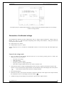
Generation of non-harmonic shapes
The multifunction calibrator can generate non-harmonic periodic signals with predefined shape. To allow the
setting of a non-harmonic output shape, the calibrator must be switched to AC U or AC I mode. In both cases, an
indication of the type of output shape (Shape xxxxx) is displayed under the frequency value. Press the respective
display button to change the shape of the output signal.
The calibrator can generate the following shapes:
SINE
PWM POS
PWM SYM
PWM NEG
RAMP A
RAMP B
TRIANGLE
LIM SINE
•
•
•
•
•
•
•
•
harmonic
squarewave - positive, with adjustable duty cycle
squarewave - symmetrical, with adjustable duty cycle
squarewave - negative, with adjustable duty cycle
ramp, symmetrical positive
ramp, symmetrical negative
triangular, symmetrical
harmonic with amplitude limitation (truncated sin)
Generation of non-harmonic signals has some limitations:
non-harmonic voltages can be generated in the 0.1 Hz to 1000 Hz frequency range
non-harmonic currents can be generated in the 0.1 Hz to 120 Hz frequency range
generation of these signals is limited to the voltage range up to 200 V and current range up to 2 A
non-harmonic signals cannot be generated in the P-E (power-energy) mode.
•
•
•
•
Control in the non-harmonic mode
•
Select AC voltage or AC current mode. The main section of the display shows the following data:
*
*
*
*
•
main data of set current or voltage, unit of measurement
relative deviation
frequency
selected SHAPE of the output signal
Keep pressing SHAPE display button to select the desired shape of the output signal:
The output terminals are automatically disconnected when changing the shape of the output signal or when
changing the relative deviation ∆%, if a non-zero relative deviation is set.
Displayed information
When non-harmonic output shape is selected, the display shows additional information:
besides the main amplitude data, “pk” index is displayed, notifying that the displayed main value is the peak
value. Symbol which displays the shape of the output signal is displayed too.
•
22
User Manual
POWERTEK
MC-140 Multifunction Calibrator
•
below the main data, an information about the shape type “Shape xxxxx” is displayed.
•
below the main data, calculated effective value of the output signal is displayed.
•
for squarewave signals, set value of duty cycle “PWM= xx %” is displayed.
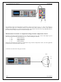
Simulation of resistance and capacitance
The multifunction calibrator can simulate an exact value of resistance or capacitance. The outputs of the
simulator are connected to Hi – Lo terminals and to AUXILIARY connector (pins 20, 21, 22, 23). 4W resistance
is accessible only via cable adapter Opt. 70.
Only two-wire connection is available on the front panel terminals Hi-Lo. Both two-wire and four-wire
connection is possible only through AUXILIARY connector. The terminals SIMHI - SIMLI are current
terminals and SIMHU - SIMLU are voltage sensing terminals. Cable adapter Option 70 or cable adapter Option
140-41 must be used for four-wire connection. Type of cable adapter currently connected to the AUXILIARY
connector, is displayed on the display. If Option 70 is connected, label CA 140-70 is displayed in the right side.
If Option 140-41 is connected, label CA 140-41 is displayed.
Cable adapter Option 70 can be used for four-wire connecting of simulated resistance only. In compare with
direct two-wire connection through output terminals Hi – Lo, accuracy of resistance is better with Option 70, see
Technical data. If Cable adapter Option 70 is connected to the AUXILIARY connector, only resistance mode
and resistance temperature simulation mode can be chosen.
The resolution of resistance and capacitance depends on the set value and corresponds to 0.01 % of set value.
Minimum set value is 0.01 Ω
Resistance simulation range is 0 Ω to 50 MΩ.
Capacitance simulation range is 0.9 nF to 50 µF.
Control in the resistance and capacitance mode
•
press R-C button on the calibrator. The display shows the set resistance.
•
If you want to simulate a capacitance, press R-C button again. The display shows the set capacitance.
•
The display shows the following data:
*
*
*
*
main data of set resistance (capacitance)
relative deviation of resistance (capacitance)
uncertainty of set resistance (capacitance)
total value of resistance (capacitance) if non-zero deviation is set
User Manual v35
23
MC-140 Multifunction Calibrator
POWERTEK
•
Set desired value of resistance (capacitance) or relative deviation. The value can be set using numeric
keyboard, potentiometer or cursor buttons. Simulated resistance (capacitance) is not yet connected to the
output terminals. The information section of the display shows the symbol which
informs
about
the disconnection of output terminals.
•
Connect the object to be calibrated to the output terminals labeled Hi - Lo.
•
Press OUTPUT button.
•
Red LED is lit above the OUTPUT terminals to indicate the connection of simulated resistance
(capacitance) to the output terminals. The information section of the display
shows
the
symbol
Simulated resistance (capacitance) is connected to output terminals.
Setting relative deviation
•
Keep pressing the center cursor button until [ _ _ _ _ _ _ _ ] symbols appear under the relative deviation
value (Δ% = xx.xxxx %).
•
The value can be set using numeric keyboard, potentiometer or cursor buttons. Confirm the value by
pressing “%” display button or by pressing ENTER.
Limitations resulting from electronic simulation
Electronic simulation of resistance and capacitance allows setting of a wide range of values with accuracy
sufficient for calibration of common multimeters. Electronic simulation has the following limitations:
•
measurement current supplied by the multimeter to be calibrated must not exceed the value specified by the
calibrator’s documentation. If the current is exceeded, the accuracy of simulated value is not guaranteed.
•
maximum peak voltage at Hi - Lo terminals supplied by the multimeter to be calibrated must not exceed
specified limits. If the test voltage is exceeded, calibrator disconnects output terminals. Overload message is
displayed on the display.
24
User Manual
POWERTEK
MC-140 Multifunction Calibrator
Frequency dependence of resistance and capacitance
Electronic simulator of resistance can be used with DC and AC test signal. Electronic simulator of capacitance
can be used in AC range from 20 Hz to 1000 Hz.
User Manual v35
25
MC-140 Multifunction Calibrator
POWERTEK
Generation of electric power and energy
The multifunction calibrator can generate exact value of electric power and energy. P-E function provides output
voltage at Hi - Lo terminals and output current at +I - -I terminals. Lo and -I terminals are electrically connected.
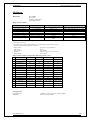
Power setting range:
Voltage setting range:
Current setting range:
Power factor setting range:
Frequency setting range:
0.0 VA to 2400 VA
0.2 V to 240 V
0.01 A to 10 A
-1 to +1 (phase –90 to +90 °)
DC, 40 Hz to 400 Hz
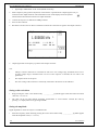
Control in power generation mode
•
Press “P-E” button on the calibrator and then select AC or DC mode by pressing “DC-AC” button. The
display shows set power value.
•
The display shows the following data::
*
*
•
main value of set power in selected unit of measurement VA, W, VAr
power factor value PF in negative polarity LA or positive polarity LE or the phase shift between the
voltage and current in °.
* frequency, if AC power is selected
* voltage at Hi - Lo terminals
* current through +I - -I terminals
* uncertainty of set power
Set desired value of power using numeric keyboard, potentiometer or cursor buttons. Output power is not
yet connected to the output terminals. The information section of the display shows the symbol
which informs about the disconnection of output terminals..
•
Connect the instrument to be calibrated to Hi - Lo and +I - -I terminals or short the +I - -I terminals.
•
Press OUTPUT button.
•
Red LED is lit above the OUTPUT terminals to indicate the connection of simulated electrical power to the
output terminals; the information section of the display shows the symbol
Desired power is connected to output terminals.
26
User Manual
POWERTEK
MC-140 Multifunction Calibrator
Display modes
The calibrator can display AC power in one of three ways:
•
•
•
apparent power in VA
active power in W
reactive power in VAr
Keep pressing MODE display button to change the function mode. Along with mode change, the power display
(depending on set power factor) and unit of measurement change as well. If DC power is generated, it is always
displayed in Watts.
The calibrator can display the phase relation of output voltage and current as power factor (–1 to +1) or as phase
shift in degrees (0 to 360 °). SETUP setup menu is used to change the method of displaying the phase relation.
Power setting modes
The calibrator allows several ways of setting the value of generated power.
1.
Setting the main power value
•
The main value can be changed using numeric keyboard, changing the digit at the cursor position
after selecting the cursor position with <, > buttons, by range change using “x10”, “:10” display
buttons, or using the potentiometer.
•
Output power is changed by changing the value of output current.
User Manual v35
27
MC-140 Multifunction Calibrator
2.
3.
28
POWERTEK
Setting the voltage
•
The main power value can be changed by changing the voltage.
•
Select P-E mode and then keep pressing the center cursor button until [ _ _ _ _ _ _ _ ] symbols
appear under the voltage (U = xxx.xxxx V).
•
The value can be set using numeric keyboard and confirmed by pressing µV, mV, V display button.
The value can be set using cursor buttons or potentiometer as well.
•
Main power value is recalculated using new set voltage and existing setting of current and power
factor.
Setting the current
•
The main power value can be changed by changing the current..
•
Select P-E mode and then keep pressing the center cursor button until [ _ _ _ _ _ _ _ ] symbols
appear under the current (I = xx.xxxx A).
•
The value can be set using numeric keyboard and confirmed by pressing µA, mA, A display button.
The value can be set using cursor buttons or potentiometer as well..
•
Main power value is recalculated using new set current and existing setting of voltage and power
factor.
User Manual
POWERTEK
4.
MC-140 Multifunction Calibrator
Setting the power factor (AC power only)
•
If W or Var is indicated, the main power value can be changed by changing the power factor.
Change of power factor does not change the output apparent power.
•
Select P-E mode and then keep pressing the center cursor button until [ _ _ _ _ _ _ _ ] symbols
appear under the power factor symbols (PF = x.xxx LA (LE) or Phase = xxx.x).
•
The value can be set using numeric keyboard and confirmed by pressing LA/LE (°) button or by
pressing ENTER.
•
Main power value is recalculated using new set power factor and existing setting of current and
voltage. The calculation is only made if active or reactive power is displayed.
In the power generation mode, relative deviation cannot be set.
If the power factor is set to define the phase relation of voltage and current, confirmation of entered
value by pressing LA button means positive phase, LE means negative phase.
Setting the energy
Keep pressing the P-E button to switch to the energy generation mode. Auxiliary data display area
shows the time in seconds and the energy delivered to output terminals after pressing the OUTPUT
button given the existing setting of voltage, current, frequency and power factor. Time setting range is
1.1 s to 1999 s.
User Manual v35
29
MC-140 Multifunction Calibrator
POWERTEK
The energy value can be set in two ways:
Direct setting of energy
•
Select the energy mode and then keep pressing the center cursor button until [ _ _ _ _ _ _ _ ] symbols
appear under the time value (E = xxx.xxxx) supplemented with indication of the set mode.
•
The value can be set using numeric keyboard, cursor buttons or potentiometer and confirmed by pressing
Ws/kWs/MWs, VAs/kVAS/MVAs or VArs/kVArs/MVArs display buttons depending on the set mode. The
value can also be confirmed by pressing ENTER.
•
Time value is recalculated using new set energy.
Setting the time
•
Select the energy mode and then keep pressing the center cursor button until [
appear under the time value (t = xxx.x s).
_ _ _ _ _ _ _ ] symbols
•
The value can be set using numeric keyboard, cursor buttons or potentiometer and confirmed by pressing
“s” display button depending on the set mode. The value can also be confirmed by pressing ENTER.
•
Energy value is recalculated using new set time.
Grounding of the calibrator and the instrument to be calibrated in the P-E mode
When calibrating the power and energy meters with separate voltage and current circuits, it is advisable
to select GND U ON and GND I ON (both grounding methods on) on the MC-140 calibrator. This
setting will ground both the current and voltage output of the calibrator.
If the instrument to be calibrated has electrically connected and not grounded current and voltage
inputs, GND U ON and GND I OFF should be selected on the MC-140 calibrator.
If Lo and -I terminals on the calibrator are connected AND the same terminals are connected at the
instrument to be calibrated, resulting voltage drop at the current cables can damage the relay which
interconnects Lo and -I terminals with GND terminal in the calibrator.
“Operating examples” chapter provides more information concerning correct connection of powermeters and
energy meters to the calibrator.
30
User Manual
POWERTEK
MC-140 Multifunction Calibrator
Uncertainty calculation of set power
Uncertainty of set power displayed on the Accuracy line of the display is calculated according to the following
formula:
for active power
d P = √ ( dU2 + dI2 + dPF2 + 0.032)
for reactive power
d P = √ ( dU2 + dI2 + dPF*2 + 0.032) [%]
for apparent power
d P = √ ( dU2 + dI2 + 0.032) [%]
where
dP is the uncertainty of set power
dU is the uncertainty of set voltage
dI is the uncertainty of set current
dPF is the uncertainty of set PF (cosϕ)
dPF* is the uncertainty of set sinϕ
[%]
[%]
[%]
[%]
[%]
[%]
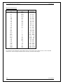
Generation of frequency
The multifunction calibrator can generate several different voltage shapes with exact frequency, amplitude and
duty cycle. The output signal is present at BNC coaxial connector FREQ located at the front panel. The signal is
not present at any other output terminal.
There are two frequency generation modes. The first mode (PWM) allows the generation of squarewave output
signal with calibrated amplitude, frequency and duty cycle. Frequency range is up to 10 kHz. The second mode
(HF) also provides squarewave output signal with very steep rising edge, typically less than 3 ns.
PWM mode
Frequency range:
Voltage range:
Signal shapes:
HF mode
Frequency range:
Voltage range:
Signal shapes:
0.1 Hz to 100 kHz
1 mV to 10 Vpp
squarewave, negative PWM NEG – symmetrical PWM SYM – positive
PWM POS
0.1 Hz to 20 MHz
5 Vpk-pk 0, -10, -20, -30 dB
symmetrical squarewave
PWM mode can be used to calibrate the input sensitivity of oscilloscopes at frequencies up to 10 kHz. HF mode
can be used to calibrate the time base of oscilloscopes.
To switch between the modes, keep pressing “F” direct mode button. The display includes the symbols for
currently selected mode (PWM or HF).
Control in the frequency mode
•
Press F direct mode button. The calibrator switches to PWM mode. If HF mode is desired, press F button
once more. The main data on the display is the frequency.
•
The display shows the following data:
*
*
*
*
set frequency
relative deviation of frequency
signal amplitude (PWM mode ) or attenuation (HF mode)
duty cycle (PWM mode only)
User Manual v35
31
MC-140 Multifunction Calibrator
*
POWERTEK
signal shape: PWM NEG / POS / SYM (PWM mode only)
•
Set the frequency using numeric keyboard, cursor buttons or potentiometer. Output signal is not yet
connected to the output terminals. The information section of the display shows the symbol
which informs about the disconnection of output terminals...
•
Connect the object to be calibrated to FREQ terminal.
•
Press OUTPUT button.
•
Red LED is lit above the OUTPUT terminals to indicate the connection of signal to the output connector.
•
Output signal with set frequency is present at the output connector.
Note
•
“FREQ” connector must not be overloaded. In 100 mV to 10V voltage range, maximum load is 5 mA.
In other voltage ranges, maximum load is 0.1mA. If the output is overloaded, the set value is not
guaranteed.
•
The output is short-circuit proof.
•
The outer casing of the connector is electrically connected to the chassis of the calibrator.
Setting relative deviation
•
Keep pressing the center cursor button until [ _ _ _ _ _ _ _ ] symbols appear under the relative deviation
value Δ% = xx.xxxx %.
•
The value can be set using numeric keyboard, potentiometer or cursor buttons. Confirm the value by
pressing “%” display button or by pressing ENTER.
Setting the amplitude
Signal amplitude in Volts can only be set in PWM mode.
Select the frequency mode and keep pressing the center cursor button until [ _ _ _ _ _ _ _ ] symbols appear
under the amplitude value (U = x.xxx V).
•
32
User Manual
POWERTEK
•
MC-140 Multifunction Calibrator
Set the value using numeric keyboard and confirm by pressing “V” display button or by pressing ENTER.
Setting the attenuation
Signal attenuation in dB can only be set in HF mode. Attenuation can be set in steps of (0, -10, -20, -30) dB.
•
Select the frequency mode and keep pressing the center cursor button until [ _ _ _ _ _ _ _ ] symbols appear
under the attenuation value (a = x.xxx dB).
•
Set the value using numeric keyboard and confirm by pressing dB display button or by pressing ENTER. If
other than permitted value is set, the closest permitted value is used.
User Manual v35
33
MC-140 Multifunction Calibrator
POWERTEK
Setting the duty cycle
Duty cycle can only be set in PWM mode.
•
Select the frequency mode and keep pressing the center cursor button until [ _ _ _ _ _ _ _ ] symbols appear
under the duty cycle value (PWM = xx %).
•
Set the value using numeric keyboard, cursor buttons or potentiometer and confirm by pressing % display
button or by pressing ENTER.
Setting the signal shape
Signal shape can only be set in PWM mode.
•
Keep pressing SHAPE display button to select desired signal shape NEG – negative, SYM – symmetrical,
POS – positive.
•
Output signal of desired shape is connected to the output connector.
Simulation of temperature sensors
The multifunction calibrator can simulate resistance temperature sensors and thermocouples. When resistance
temperature sensors are simulated, a simulated resistance corresponding to set temperature, sensor type and
temperature scale is connected to Hi - Lo terminals. When thermocouples are simulated, a simulated voltage
corresponding to set temperature, sensor type and temperature of cold end of thermocouple is connected to Hi Lo terminals.
Simulated values of temperature sensors are also available at the AUXILIARY connector. Thermocouple voltage
is available at +U, -U terminals. Four-wire connection of resistance temperature sensors is provided by current
terminals PTLI, PTHI and voltage terminals PTLU, PTHU. 140-41 cable adapter is recommended.
Temperature setting range:
Sensor types:
Temperature scale:
-250 to +1820 oC depending on simulated sensor type
resistance temperature sensor Pt 1.385, Pt 1.392, Ni
thermocouple K, N, R, S, B, J, T, E
ITS 90, PTS 68 for resistance temperature sensors and thermocouples
Switching between resistance temperature sensors and thermocouples
•
Press T button on the calibrator. The main value on the display is set temperature. The calibrator simulates a
resistance temperature sensor.
•
Press T button on the calibrator once again. The calibrator simulates a thermocouple.
Setting the temperature
•
Press T button on the calibrator. The main value on the display is set temperature.
•
The display shows the following data:
*
34
main data of temperature in oC or K
User Manual
POWERTEK
*
*
*
*
MC-140 Multifunction Calibrator
sensor type
thermocouples:
K, N, R, S, B, J, T, E
resistance temperature sensors:
Pt 1.385, Pt 1.392, Ni
resistance at 0 o C labeled R0 (resistance temperature sensors only)
cold junction temperature of thermocouple sensors labeled RJ
set value of relate deviation in %, labeled ΔT = xxxx.x °C (K)
the information section shows:
*
*
temperature scale type
uncertainty of simulated temperature value of selected temperature sensor type
•
Set the main value of temperature using numeric keyboard, cursor buttons or potentiometer. Output
terminals are disconnected, the information section of the display shows
the symbol which shows
that output terminals are disconnected.
•
Connect the object to be calibrated to Hi - Lo terminals.
•
Press OUTPUT button.
•
Red LED is lit above the OUTPUT terminal to indicate that the output signal is connected to output
terminals. The display shows the symbol of connected output terminals.
Note
•
Load of output terminals is limited similarly to corresponding voltage or current ranges.
•
Output signals provided at Hi - Lo terminals and AUXILIARY connector are short-circuit proof.
Switching between temperature sensor types
•
Keep pressing “TC type” or “RTD type” display button to select desired sensor type.
•
If resistance temperature sensors are selected, each press of the button selects Pt1.385, Pt1.392 or Ni
resistance thermometer. The display shows current setting as Pt385 / Pt392 / Ni.
•
If thermocouples are selected, each press of the button selects K, N, R, S, B, J, T, E types. The display
shows current setting as TC TYPE x, where x is the type of the thermocouple
User Manual v35
35
MC-140 Multifunction Calibrator
POWERTEK
Entry of R0 coefficient for resistance temperature sensors
For resistance temperature sensors, resistance at 0 oC labeled R0 can be set. The range is 20 Ω to 2kΩ for all
types of resistance temperature sensors.
•
Select the resistance temperature sensor mode and keep pressing the center cursor button until
[ _ _ _ _ _ _ _ ] symbols appear under the R0 coefficient value (R0 = xxxx Ω).
•
Set the value using numeric keyboard and confirm by pressing “ Ω” or “kΩ ” display button or
by pressing ENTER.
Note
After the calibrator is switched on or before the first change of the coefficient, R0 is set to 100 Ω. This setting
corresponds to Pt 100 resistance thermal sensor.
Entry of cold junction temperature
For thermocouples, the temperature of cold junction can be entered. The entry is performed by setting the RJ
field in the auxiliary data section of the display.
36
•
Select the thermocouple mode and keep pressing the center cursor button until [ _ _ _ _ _ _ _ ]
symbols appear under the (RJ = xxxx.x oC) value, if o C unit of measurement is used, or under
(RJ = xxxx.x K) value, if K unit of measurement is used.
•
Set the value using numeric keyboard.
•
Confirm the value by pressing oC or K display button or by pressing ENTER.
User Manual
POWERTEK
MC-140 Multifunction Calibrator
Automatic compensation of cold junction temperature
Automatic cold junction TC sensors compensation can be performed, when cable adapter Option 140-01 is used
for simulating. Ambient temperature measured by in cable adapter mounted Pt1000 sensor is taken as
temperature of cold junction. This automatic compensation is performed always, when measuring of ambient
temperature is activated on display (push button INPUT ON, green led lights). When temperature measuring is
not activated or cable adapter Option 140-01 is not connected, manual compensation only is available. Set value
of RJ on the display to the appropriate ambient temperature to compensate manually influence of cold junction.
Use of AUTOCAL function
To remove the effects of short-term drift and thermal dependency of the simulation, AUTOCAL function can be
used. It can only be activated in the calibration mode. Procedure is following:
•
Use a display button to enter the calibration menu. Enter the calibration code and confirm by pressing
ENTER.
•
Use the cursor buttons or potentiometer to select the AUTOCAL function from the calibration menu. After
the function is activated, only one option - OFFSET ACAL - is provided. Press SELECT display button to
confirm the option.
•
Proceed according to the instructions provided on the display. Automatic calibration takes ca 8-10 minutes
and prompts the user to short Hi-Lo circuits and then to disconnect them.
•
After the calibration, the calibrator remains in the calibration mode. Press EXIT display button to return to
normal display.
Do not connect anything to any terminals during the automatic calibration, with the exception of the prompt to
short the Hi-Lo terminals. The procedure is described in “Calibration mode” chapter.
User Manual v35
37
MC-140 Multifunction Calibrator
POWERTEK
Multimeter
The calibrator includes a built-in multimeter which can measure many electrical and non-electrical values.
Besides DC voltage and current, it can measure frequency, temperature and when external strain gauge sensors is
connected, even other non-electrical values can be measured. The multimeter can only be connected through
AUXILIARY connector. “Description of controls” chapter lists the pins of the connector.
The manufacturer recommends 140-41 cable adapter or Option 40 cable terminal to connect the multimeter. 14041 cable adapter includes a fuse which protects the multimeter from current overload.
The manufacturer does not recommend connection of multimeter inputs to
calibrator outputs.
Such connection can result in presence of high voltage at multimeter inputs,
which can damage the multimeter.
Basic menu
•
Multimeter setting menu can be opened by pressing the METER direct control button. After the button is
pressed, SETUP METER menu opens, which allows to set-up the multimeter. Press EXIT display button to
return to previous menu.
•
Press ∧ or ∨ cursor button to browse the menu options. Active option is always inverted.
•
The parameters of the active option can be changed if the respective function is allowed to be changed. Use
UP, DOWN, CLR, NEXT and display buttons to change the parameters of the active option.
•
Multimeter parameters can also be set using the potentiometer. The potentiometer can be used either to
browse the menu options or to change the value of the active option. Press the knob to switch between these
modes.
•
Keep pressing EXIT display button to return to normal display when you are finished setting up the
parameters.
38
User Manual
POWERTEK
MC-140 Multifunction Calibrator
When the multimeter is being set-up, measurement cannot be initiated. Measurement can only be initiated after
the menu is left using the INPUT button.
Function selection
•
Press METER direct control button and select FUNCTION option from the menu using cursor buttons.
•
Press UP, DOWN display buttons or use the potentiometer to select one of the following functions:
*
*
*
*
*
*
*
*
basic DC voltage range VDC 10 V
DC current mA DC 20 mA
small DC voltage range mV DC up to 2 V
four-wire resistance measuring range up to 2 kΩ
frequency up to 15 kHz
temperature measurement using thermocouples T TC
temperature measurement using resistance temperature sensors T RTD
measurement of strain gauges (pressure, force) SGS
•
By selection of the measurement function, some related options are automatically changed as well
(measuring range, unit of measurement).
•
Press EXIT display button the close the function selection menu and to return to the basic display.
Setting the measurement range
•
Press METER direct control button and select RANGE option from the menu using cursor buttons.
•
Press UP, DOWN display buttons or use the potentiometer to select the measurement range for selected
function. Ranges of individual functions can be changed:
*
*
*
*
small DC voltages mV DC ranges:
20, 200, 2000 mV
temperature measurement using thermocouples T TC, types: K, N, R, S, B, J, T, E
temperature measurement using RTD sensors, types:
Pt 1.385, Pt 1.392
setting of sensitivity of strain gauge sensors (pressure, force) SGS
User Manual v35
39
MC-140 Multifunction Calibrator
POWERTEK
After setting the range, use ∧ or ∨ cursor buttons to switch to the previous or next menu option. The same
can be achieved using the potentiometer after pressing the knob. Press EXIT display button the close the
range selection menu and to return to the basic display.
•
Units of measurement
Unit of measurement can be set for each measurement function. The unit of measurement is displayed along with
the measured value on the display. The description of the unit of measurement can consist of up to 4 characters.
•
Press METER direct control button and select UNIT option from the menu using cursor buttons.
•
Press the knob of the potentiometer to display ∧ and ∨ symbols above the active character.
•
Press UP, DOWN display buttons or use the potentiometer to select desired character at the active position.
•
Press NEXT display button to move onto next character.
•
Press the knob of the potentiometer to complete the setting.
•
After the unit of measurement is selected, use ∧ or ∨ cursor buttons to move onto the next menu option. The
same can be achieved using the potentiometer after pressing the knob. Press EXIT display button the close
the range selection menu and to return to the basic display.
If you want to reset the unit of measurement to original setting, press CLR display button. Original settings are
listed below:
*
*
*
*
*
*
*
*
40
basic DC voltage range VDC
DC current mA DC 20 mA
small DC voltages mV DC up to 100 mV
four-wire resistance measurement
frequency up to 15 kHz
temperature measurement using
thermocouples
temperature measurement using resistive
temperature sensors
measurement of strain gauge sensors
V
mA
mV
Ω
Hz
°C
°C
mV/V
User Manual
POWERTEK
MC-140 Multifunction Calibrator
Use of calculation formula
Each function of the multimeter can display recalculated measured value. The value shown on the display is
always calculated according to the formula:
Y = A0 + A1*X + A2 * X2
where
X is the value measured by the multimeter
Y is the value shown on the display
Default setting of the coefficients is A0 = 0, A1 = 1, A2 = 0. This means that directly measured value is
displayed on the display. If any other recalculation is required, enter the desired parameters. Parameter A0 must
be of the same dimension as is in row UNIT.
•
Press METER direct control button and select A0 (A1, A2) option from the menu using cursor buttons.
•
Enter new value using numeric keyboard.
•
Confirm the value by pressing ENTER.
•
After setting the coefficients, use ∧ or ∨ cursor buttons to switch to the previous or next menu option. The
same can be achieved using the potentiometer after pressing the knob. Press EXIT display button the close
the range selection menu and to return to the basic display.
If you want to reset a coefficient to original setting, press CLR display button.
Each measurement function of the multimeter has its own independent set of coefficients.
Setting function parameters
Some measurement functions have additional parameters. When measuring the temperature using RTD sensors,
R0 (resistance at 0 °C) can be set, when measuring the temperature using TC sensors, the temperature of cold
junction can be set and when measuring using SGS sensors, supply voltage of the bridge can be set.
Original settings are listed below:
T RTD
R0 = 100 Ω
T TC
RJ =23 °C
SGS
Voltage = 5 V
The parameters can be changed as follows:
•
Press METER direct control button and select a function, then use cursor buttons to select the line which
includes the function parameter.
•
Enter new value using numeric keyboard.
•
Confirm the value by pressing ENTER.
•
After setting the coefficients, use ∧ or ∨ cursor buttons to switch to the previous or next menu option. The
same can be achieved using the potentiometer after pressing the knob. Press EXIT display button the close
the range selection menu and to return to the basic display.
User Manual v35
41
MC-140 Multifunction Calibrator
POWERTEK
Start of measurement
To start a measurement:
•
Press INPUT direct control button in the basic state of the calibrator.
•
INPUT field on the display shows the measured value. The measurement is indicated by a green LED above
the INPUT button.
•
Press INPUT button again to stop the measurement. The LED goes off and the input connectors are
disconnected.
The multimeter does not display uncertainty of measuring. If the input range is exceeded, OVERFLOW message
is displayed.
140-41 Cable adapter must be used to connect the signal.
Zero function
The multimeter has a zeroing function. It can be activated after the measurement was activated by pressing
INPUT direct control button. Zeroing is performed by pressing METER direct control button. After the button is
pressed, most recent value is stored and subtracted from all ongoing measured values. A “Zero” message appears
on the right side of the display, indicating that this function is active. Press METER a second time to deactivate
the Zeroing function.
Multimeter’s menu can be entered only after the measurement is terminated by pressing INPUT button.
42
User Manual
POWERTEK
MC-140 Multifunction Calibrator
Zeroing function can be used e.g. to compensate the voltage drops at the cables, to suppress any remanent value
of the signal etc.
Overloading can damage the multimeter.
Notes:
*
The current inputs of the multimeter are protected from current overloading by a fuse located in 140-41
cable adapter. The fuse can be replaced after turning the cap of the fuse holder. The procedure is
described in the adapter’s manual.
*
The multimeter can be used as a DC milivoltmeter with 20 mV, 200 mV, 2 V, 10 V ranges. The
appropriate input terminals are PTHU and PTLU.
*
Maximum allowed voltage on the input terminals against ground terminal is 20 V.
*
Frequency measurement is possible up to 15 kHz. Input signal must be within 0.2 to 5 V range.
squarewave or pulse shape of the input signal is expected.
User Manual v35
43
MC-140 Multifunction Calibrator
POWERTEK
Simultaneous functions
The multifunction calibrator allows simultaneous generation of calibrated signal along with measurement of
another signal using the built-in multimeter. To use both parts of the calibrator simultaneously, cable adapters
supplied by the manufacturer are necessary.
When using the calibrator, the following states are possible; each state has its limitation, listed in the table.
Method of use
Limitation of output signals
1
No cable adapter is used.
Calibrator’s output signals are not The multimeter cannot be
limited in any way and can be fully used.
used.
If the multimeter is activated,
Calibrator’s output signals are
FAIL error message appears.
available only at the terminals
located at the front panel.
2
The calibrator is used with
140-01 cable adapter.
Calibrator’s output signals are not The multimeter can only be
limited in any way and can be fully used to measure the external
used.
temperature using a Pt100
sensor built into the adapter.
Calibrator’s output signals are
available only at the terminals
located at the cable adapter.
140-01 cable adapter
connected onto calibrator’s
terminals.
3
The calibrator is used with
140-41 designed for
simultaneous measurement.
Calibrator’s output signals are
available only at the terminals
located at the cable adapter; ranges
are limited to:
- DC voltage up to 20 V
- DC current up to 20 mA
- four-wire resistance
measurement.
Calibrator’s output signals are only
available at the terminals located at
the front panel in full ranges and
can be fully used.
The multimeter can be used
without limitations and in full
ranges.
140-41 cable adapter
connected onto calibrator’s
terminals.
SGS sensors can be
connected.
OUTPUT 140-41 AUX
The multimeter can be used
without limitations and in full
ranges.
140-41 cable adapter
connected onto calibrator’s
terminals.
SGS sensors cannot be
connected
OUTPUT 140-41 PANEL
OUTPUT 140-41 function is
set to AUX
4
The calibrator is used with
140-41 designed for
simultaneous measurement.
OUTPUT 140-41 function is
set to PANEL.
Calibrator’s output signals are not
available at the terminals of the
cable adapter.
Limitation of multimeter’s
function
Method of connection
5
The calibrator is used with
Option 40 Canon – 2 banana
cable end.
Calibrator’s output signals are not The multimeter can be used in
limited in any way and can be fully the following ranges:
used.
- DC voltage up to 12 V
- DC voltage up to 25 mA
Calibrator’s output signals are only - frequency up to 15 kHz.
available on the terminals located
at the front panel.
Option 40 Cable, connected
onto calibrator’s
AUXILIARY connector.
6
The calibrator is used with
Option 60 Canon – 4 banana
cable end..
Calibrator’s output signals are not The multimeter can only be
limited in any way and can be fully used in the following ranges:
used.
- temperature using TC
sensors
Calibrator’s output signals are only - temperature using RTD
available at the terminals located at sensors
the front panel.
- resistance up to 2 kOhm
SGS sensors cannot be
connected.
Option 60 cable end ,
connected onto calibrator’s
AUXILIARY connector
7
The calibrator is used with
Option 70 Canon – 4
terminals.
Following output signals can be set Multimeter cannot be used.
only:
If the multimeter is activated,
- resistance in four-wire
FAIL error message appears.
connection
– resistance temperature sensor
simulation in four-wire connection
Cable adapter Option 70,
installed on AUXILIARY
connector.
Output signals are available on
adapter Option 70 only.
44
User Manual
POWERTEK
MC-140 Multifunction Calibrator
If current is drawn from +I and –I output terminals located at 140-41 cable adapter, +I and –I output terminals
located at calibrator’s front panel must not be connected simultaneously.
“Operating examples” chapter provides examples of correct connection during simultaneous measurements.
User Manual v35
45
MC-140 Multifunction Calibrator
POWERTEK
Tester
The calibrator includes an application SW, which facilitates automated testing of regulators and transducers.
Tester function combines the use of the calibrator as the source of precision signal with automatic change of
output signal, while the response of the unit being tested is measured by the calibrator’s built-in multimeter. The
calibrator is capable of subsequent processing of measured values, providing PASS/FAIL indication.
Tester function comprises of performance of a programmed sequence of up to 10 steps. For each step, the type
and value of output signal and the type and tolerance of input signal can be defined. If the input signal is not
within the tolerance limit, the respective step of the test program is considered failed. The time between
individual steps can be set as well.
Basic menu
•
Press SETUP display button to enter the Tester mode. After the button is pressed, the bottom line of the
display shows TESTER option. Press the respective display button to open the menu of test programs.
•
The menu includes a sequence number of the test program, date of creation and program name.
•
Use the cursor buttons or the knob of the potentiometer to select the desired test program. Press EXECUTE
display button to execute the program or SELECT to edit the program.
Execution of test program
After EXECUTE display button is pressed to execute the test program, the calibrator displays a screen with set
parameters of output signal and set configuration of the multimeter. The calibrator displays PROGRAM
NUMBER and STEP information above the main output data when the test program runs. PROGRAM
NUMBER xx, where xx can be 00 to 09, designates the test program which currently runs. STEP (max. 10)
designates current step of the program.
46
User Manual
POWERTEK
MC-140 Multifunction Calibrator
After the test program concludes, the calibrator displays a table showing the results. The table includes the
sequence number of each step, set output value of the calibrator, the value measured by the multimeter and the
result of the respective test step (PASS/FAIL).
Total number of failed steps is displayed above the table (xx ERRORS) along with the designation of performed
test.
After reviewing the results of the test, press EXIT display button to return to the previous level. The test can be
interrupted by pressing CANCEL button.
Programming the test
Test procedures can be programmed after you select a procedure in the basic Tester menu and press SELECT
display button. The calibrator displays a programming table.
Two basic test parameters can be set:
•
definition of the type of input and output signals and the number of steps
•
numeric values for each step
User Manual v35
47
MC-140 Multifunction Calibrator
POWERTEK
Setting the type of signals and the number of steps
Type of output signal can be set using OUTPUT display button. Press the button repeatedly to select the signal
which will be generated at the output terminals after the test program is executed. The following options are
available:
VDC – VAC – ADC – AAC – WDC – WAC – R – C – T RTD – T TC – F PWM – F HF
Selected type of output signal is displayed in the header of the programming table, “Output” column. The values
in the table change when the type of the output signal is changed.
Type of measured signal (input) can be set using INPUT display button. Press the button repeatedly to select
the signal which will be measured at the input terminals by the built-in multimeter after the test program is
executed. The following options are available:
V DC – mA DC – mV DC – R 4W – Freq – T TC – T RTD
Explanation of symbols:
V DC
mA DC
mV DC
R 4W
Freq
T TC
T RTD
DC voltage measurement in 12 V range
DC current measurement in 25 mA range
DC voltage measurement in 20 mV to 2 V range(automatic range switching)
four-wire measurement of resistance
measurement of frequency up to 15 kHz
measurement of temperature using thermocouple
measurement of temperature using resistance temperature sensor
If T TC or T RTD functions are used, the parameters set for the multimeter mode apply. The settings include the
type of unit of measurement (K – °C), temperature scale (ITS68 – PTS90), sensor type, temperature of cold
junction of thermocouple (RJ) and resistance at 0 °C.
Selected type of input signal is displayed in the header of the programming table, “Input” column. The values in
the table change when the type of the input signal is changed.
Number of test steps can be set by pressing STEPS display button in the range 1 to 10. Set number of steps is
displayed in the header of the programming table, “Steps” column. The number of the rows in the table changes
when the number of steps is changed. You can select the lines in the table by pressing ∨, ∧ buttons or by turning
the knob of the potentiometer.
Setting the numeric values of the test
After the type of output signal is selected, numeric values of individual steps can be set. The following
parameters can be set for each step:
1. Value of OUTPUT signal. The range valid for the respective output signal can be used.
If DC voltage or DC current are programmed, only the voltage or current can be set, not the frequency. The
calibrator uses the frequency which has been previously set for the respective output function.
If PWM or HF frequency output is selected, only the frequency can be set. The calibrator uses the output
voltage and duty cycle which has been previously set for the respective output function.
If power output (W AC, W DC) is selected, only W can be selected. The calibrator uses constant voltage,
power factor (phase) and frequency which have been previously set in power generation mode. Change of
power set in the programming table is achieved by change of output current during the test.
2. Lower tolerance limit of input value (LOW). The limit can be set within the selected range of the
multimeter.
3. Upper tolerance limit of input value (HIGH). The limit can be set within the selected range of the
multimeter.
4. Duration of each program step in seconds (TIME). Setting range is 0.5 to 100 s.
48
User Manual
POWERTEK
MC-140 Multifunction Calibrator
Programming of values is done as follows:
• Select the value to be changed by cursor buttons or the knob of the potentiometer.
• Enter the numeric value using the units of measurement displayed in the header of the table.
•
•
•
Confirm the entry by pressing ENTER. New entry is copied to the respective position.
This way, all numeric entries in the table can be changed.
Press EXIT display button to return to the previous level when the programming is complete.
Note:
When the test program is executed, all steps are performed.
Within one test program, only one type of input signal and output signal can be used. It is impossible to switch to
other function of the calibrator in the middle of a program.
Setting the relays
SWITCH POLARITY and SWITCH ACTIVITY items of SETUP MENU are used to set-up the relay. The
following table lists the states of the relay depending on the values of SWITCH POLARITY, SWITCH
ACTIVITY and the test result.
SETUP MENU
Switch polarity
OFF
Switch activity
PASS
Switch polarity
ON
Switch activity
PASS
Switch polarity
OFF
Switch activity
FAIL
Switch polarity
ON
Switch activity
FAIL
RELAY BEFORE TEST
TEST RESULT
RELYA AFTER TEST
disconnected
FAIL
disconnected
PASS
connected
FAIL
connected
PASS
disconnected
FAIL
connected
PASS
disconnected
FAIL
disconnected
PASS
connected
connected
disconnected
connected
Setup menu
User Manual v35
49
MC-140 Multifunction Calibrator
POWERTEK
The multifunction calibrator allows many other, less frequently used parameters to be set. Setup menu is used to
set these parameters. Setup menu is opened by pressing SETUP display button. If output terminals are
connected, they will be disconnected and the following display appears:
Use ∧ or ∨ cursor button or the knob of the potentiometer to browse the menu options. Active option is always
inverted and when changed, the descriptions of display buttons change as well. Display buttons show how the
respective parameter can be set. Each parameter can be changed after the knob of the potentiometer is pressed.
Press EXIT display button twice to save the parameters when the setting is completed. New settings are retained
when the calibrator is switched off. Setup menu offers the following options:
1.
Coil x50 .... xx
ON/OFF
This parameter can be set on when 50-turn current coil is going to be used for clamp ammeter calibration. The
coil multiplies the output current. OFF is set by the manufacturer.
2.
GND U .... xx
ON/OFF
This parameter connects Lo terminal to GND. In practice this means that Lo terminal is grounded. By pressing
the display buttons, the terminal can be grounded or ungrounded. ON is set by the manufacturer, output terminal
is grounded.
3.
GND I .... xx
ON/OFF
This parameter connects -I to GND. In practice this means that -I terminal is grounded. By pressing the display
buttons, the terminal can be grounded or ungrounded. OFF is set by the manufacturer, output terminals are not
grounded.
It is recommended to ground only the voltage channel GND U ON, GND I OFF, for all ranges except the
generation of power or energy. If the meter to be calibrated has Lo terminal grounded, it is recommended to
unground both outputs of the calibrator, GND U OFF, GND I OFF to exclude ground loops.
Note
If neither the calibrator’s output, nor the meter’s inputs are grounded, signal/noise ratio can arise at the
calibrator’s output.
50
User Manual
POWERTEK
4.
Temp.scale .... xx
MC-140 Multifunction Calibrator
ITS90/PTS68
This parameter allows the temperature scale for platinum resistance temperature sensors to be selected. Pressing
the display buttons allows to switch between ITS90 and PTS68 temperature scales. ITS90 is set by the
manufacturer.
5.
Temp.unit .... xx
o
C/K
This parameter allows the temperature unit for simulation of temperature sensors to be selected. Pressing the
display buttons allows to switch between °C and K. °C is set by the manufacturer.
6.
Phase.unit .... xx
o
/cos
This parameter allows the unit of phase shift between the voltage and current output to be selected in the
power/energy generation mode. Pressing the display buttons allows to switch between ° and COS (degrees and
power factor).
7.
Output 140-41 .... xx AUX/PANEL
This parameter allows the output terminals to be selected. AUX means that the output signals are present only at
the cable adapter’s terminals, PANEL means that the output signals are present only at the front panel.
8.
Meter average .... xx
UP/DOWN
Displays the number of measurements taken before the average value of build-in multimeter is displayed
(integration constant). UP, DOWN display buttons can be used to select a value in the range of 1 to 20. The
higher the value, the longer the calibrator needs to measure a value, but displayed value is more stable. If 20 is
set, one measurement takes approximately 2.5 s.
9.
Interface .... xx
GPIB/RS232
Displays the type of interface used to control the calibrator from a PC. By pressing GPIB or RS232 buttons, the
respective type can be selected. The calibrator can be remotely controlled only using the selected interface.
10. GPIB address .... xx UP/DOWN
Displays the calibrator’s address at the GPIB bus. UP, DOWN display buttons can be used to select any valid
GBIP address in the range of 00 to 30. The address 02 is set by the manufacturer.
11. RS232 baud rate .... xx
UP/DOWN
Indicates the communication speed of RS232 bus. UP/DOWN display buttons can be used to select 150, 300,
600, 1200, 2400, 4800, 9600, 19200. Perfect communication with the PC requires equal values set at the PC and
the calibrator.
12. Handshake .... xx
OFF/Xon-Xoff
Indicates the communication handshake. Display buttons can be used to select OFF or Xon/Xoff. Perfect
communication with the PC requires equal values set at the PC and the calibrator.
13. Keyb.beep .... xx
User Manual v35
ON/OFF
51
MC-140 Multifunction Calibrator
POWERTEK
This parameter allows the acoustic indication of pressed buttons to be switched off or on. ON and OFF display
buttons can be used to switch the indication off or on. ON is set by the manufacturer.
This parameter does not control the acoustic indication of output voltages over 100 V and identification of
errors.
14. Keyb.volume .... xx
UP/DOWN
This parameter allows the volume of acoustic indication to be set. UP and DOWN display buttons allow to set
the value in the range of 00 to 15. The bigger the value, the louder sound. This parameter controls the volume of
keyboard beep (if switched on), indication of output voltages over 100 V and identification of errors when
controlling the calibrator.
15. Brightness .... xx
UP/DOWN
This parameter sets the contrast of the display. UP and DOWN display buttons allow to set the value in the range
of 00 to 15.
16. Rotary change .... xx ON/OFF
This parameter controls the range of functions of the potentiometer. If ON is set, the potentiometer can move the
cursor both to the left and right (← and → symbols) and up and down (∧ and ∨ symbols). If OFF is set, the
potentiometer can move the cursor up and down only (∧ and ∨ symbols).
17. Switch polarity .... xx ON/OFF
This parameter controls the function of the built-in relay. If ON is set, the relay is closes before the test. If OFF is
set, the relay is opens before the test.
18. Switch activity .... xx PASS/FAIL
This parameter controls the function of the built-in relay. If PASS is set, the relay is active (changes its status) if
the test results in PASS status. If FAIL is set, the relay is active (changes its status) if the test results in FAIL
status.
19. Cal.code .... 00000
Entry of calibration code. Calibration code is a five-digit number, which must be entered to access the calibration
mode. If the calibration code is set to “00000”, this information is displayed in the Setup menu. Calibration code
can be changed. New calibration code can be directly entered using numeric keyboard and confirmed by pressing
ENTER. If non-zero calibration code is set, correct calibration code must be entered to access the calibration
mode. Non-zero calibration code is not displayed further on the display.
The purpose of the calibration code is to prevent unauthorized users from changing the calibration of the
52
User Manual
POWERTEK
MC-140 Multifunction Calibrator
instrument.
Note
It is advisable to write down actual calibration code if changed. If you forget the calibration code, you have to
send the calibrator to the manufacturer.
20. Cal.date .... xx.yyyy
Displays the date of last calibration of the calibrator (month/year). The parameter cannot be changed, as it is
automatically recorded when leaving the calibration mode.
21. Serial No .... xxxxxx
Displays the serial number of the calibrator. The parameter cannot be changed.
22. Time .... xx:yy
Displays real time. The parameter can be changed using HOUR UP, HOUR DO, MIN UP, MIN DO. display
buttons.
23. Date .... xx.yy.zzzz
Displays real time. The parameter can be changed using DAY UP, MONTH UP, YEAR UP, YEAR DO display
buttons.
24. Time on display .... xx
ON/OFF
If set to ON, time and date are displayed in the upper part of the display. If OFF is set, time and date are not
displayed. ON is set by the manufacturer.
User Manual v35
53
MC-140 Multifunction Calibrator
POWERTEK
Calibration mode
The multifunction calibrator includes a calibration procedure, which allows calibration of the calibrator. Zero
point and slope of the characteristics of individual generation and measurement ranges are set during the
calibration in predefined order. The calibration can only be controlled using the buttons and menu on the
calibrator.
The calibration mode includes AUTOCAL autocalibration function. This function can automatically correct the
short-term instability of zero point for voltage ranges up to 20 V. This function is not a part of the complete
calibration procedure, but it can be used to reduce the time and temperature dependent drift of zero point when
calibrating using small DC voltages and when simulating the thermocouples.
Calibration principles
The calibrator can be calibrated:
•
•
•
completely, i.e. all functions are calibrated in all recommended points
partially, i.e. only selected functions are calibrated in all recommended points
partially, i.e. only selected functions are calibrated in selected points
Complete calibration consists of all partial calibrations performed in the order defined by the calibration menu. If
an item of the calibration menu, e.g. “VOLTAGE DC” is selected, it is not necessary to calibrate all ranges
defined by the calibration algorithm. If new calibration of all ranges is not possible (e.g. the required standard is
not available), old calibration data can be confirmed, i.e. current step of the calibration can be skipped.
Calibration interruption can be performed in any point of the calibration
procedure. However this particular calibration influences parameters of the
calibrator.
Accuracy of the calibrator is guaranteed when full calibration was done.
DC voltage calibration is performed by setting the zero and slope of the scale in all ranges and in both signal
polarities (+ and -) (except the 1000 V range, where zero correction is not necessary).
AC voltage calibration is performed by setting the zero and slope of the scale in all ranges at 1000 Hz (except
the 1000 V range, where the calibration is performed at 500 Hz).
DC current calibration is performed by setting the zero and slope of the scale in all ranges and in both signal
polarities (+ and -).
AC current calibration is performed by setting the zero and slope of the scale in all ranges at 1000 Hz (except
the 20 A, where the calibration is performed at 120 Hz).
AC and DC power calibration is performed by calibration of DC and AC current. The phase relationship of
voltage and current (power factor) is defined digitally and cannot be calibrated. It can only be checked. The
respective check is not included in the calibration procedure.
Resistance calibration is performed by setting the zero and slope of the scale in all ranges. Slope of each range is
calibrated twice. In practice, 9 internal range resistances (50 Ω to 10 MΩ) must be measured and the measured
value entered into the calibrator; then the zero point of the scale is adjusted for each range. Calibration of
resistance ranges must be performed through AUXILIARY connector. Cable adapter Option 70 must be
connected to the auxiliary output.
54
User Manual
POWERTEK
MC-140 Multifunction Calibrator
Capacitance calibration is performed by setting the zero and slope of the scale in all ranges. Slope of each range
is calibrated twice. In practice, 9 internal capacitance ranges (1 nF to 10 µF) must be measured and the measured
value entered into the calibrator; then zero point of the scale is adjusted for each range.
Frequency function calibration is performed by calibration of DC voltage range and zero point check. DC
voltage levels are checked, between which the calibrator switches when generating the signal. The accuracy of
PWM of the squarewave output signal depends on the frequency accuracy and cannot be calibrated, it can only
be checked. The respective check is not included in the calibration procedure.
Multimeter is calibrated on voltage ranges 2 V and 10 VDC voltage ranges, on current range 20 mADC and on
resistance range 2000 Ω. For calibration cable adapters Option 40 (voltage, current) and Option 60 (resistance)
must be used.
Access to the calibration procedure
Calibration code is required to access the calibration procedure.
•
Press SETUP to open the setup menu.
•
Press CALIB display button.
•
Concerning cable adapters, access to the calibration mode is permitted without connected any of cable
adapters or with connected cable adapter Option 40, Option 60 and Option 70. If cable adapter Option 14001 or Option 140-41is connected to the AUXILIARY connector, access to calibration mode is not permitted.
Calibrator will display message:
Err 9
Bad cable adapter !
•
If an attempt is made to access the calibration procedure within 60 minutes after the calibrator was switched
on, the calibrator does not open the respective menu and displays the following message instead:
Err 21
Time warm up !
xx minutes remain
•
If the calibrator is already on for at least 60 minutes, it requests the entry of the calibration code after CAL.
MODE display button is pressed.
•
Enter the correct calibration code using numeric keyboard and press ENTER.
User Manual v35
55
MC-140 Multifunction Calibrator
POWERTEK
If incorrect calibration code is entered, an error message appears on the display for approximately 3
seconds:
•
Err 20
Bad calib. code!
•
If correct calibration code is entered, calibration menu appears:
•
Use ∧ and ∨ cursor buttons to move the cursor through the list:
1.
2.
3.
4.
5.
6.
7.
8.
9.
10.
11.
VOLTAGE DC
VOLTAGE AC
CURRENT DC
CURRENT AC
POWER DC
POWER AC
RESISTANCE
CAPACITANCE
FREQUENCY
ANALOG INPUT
AUTOCAL
All DC voltage ranges calibration
All AC voltage ranges calibration
All DC current ranges calibration
All AC current ranges calibration
DC power calibration
AC power calibration
Resistance calibration
Capacitance calibration
Amplitude in frequency mode calibration
Multimeter calibration
DC voltage offset correction
Selection of calibration type
After the calibration menu is displayed, one of partial calibrations can be selected. Use ∧ and ∨ cursor buttons to
move the cursor through the list. Having selected the required function to be calibrated, press SELECT display
button. The following data are shown (the following example is valid for VOLTAGE DC range):
56
User Manual
POWERTEK
MC-140 Multifunction Calibrator
The table lists recommended calibration points. Having selected the required calibration point using SELECT
display button, the following data are shown.
Display buttons have the following meaning:
WRITE
new calibration value is entered into the memory, old value is irreversibly lost
SKIP
current calibration step is skipped, old value is retained in the memory
EXIT
current calibration is terminated. After this button is pressed, the calibration memory
hold all data (old or new entered) and the calibrator returns to the calibration
menu. It is not necessary to calibrate all ranges; calibration of only selected ranges
is possible by skipping the ranges which do not need to be calibrated.
Moreover, the display shows the range which is being calibrated (RANGE), and the value to be set at the
external standard multimeter (VALUE).
Setting the new calibration data
Use ∧, ∨, <, > cursor buttons to set such main data on the display, when the output signal measured by external
standard multimeter reaches the required calibration point. When the standard output value is reached, press
“WRITE” to write new calibration value to the calibration memory. If you press “SKIP” button, the calibrator
User Manual v35
57
MC-140 Multifunction Calibrator
POWERTEK
ignores the new value and old value is retained. After you press “WRITE” (or “SKIP”), the calibrator moves on
to the next calibration point.
The procedure is repeated for all calibration points of the selected function. If you press “EXIT” button before
completing the calibration, the calibrator returns to the calibration menu.
Termination of calibration
The calibration can be terminated in the following cases:
•
complete calibration has been performed, new calibration data have been entered, the program has returned
to the calibration menu,
•
calibration of selected function has been performed, new calibration data have been entered, the program
has returned to the calibration menu,
•
calibration of selected range(s) of selected function has been performed, new calibration data have been
entered, the program has returned to the calibration menu,
•
the calibration has been started but no calibration data have been entered, the program has returned to the
calibration menu after “EXIT” display button has been pressed,
Press “EXIT” display button to terminate the calibration. After the button is pressed, the calibration date is saved
internally and the calibrator returns to the state it was in before the calibration has been started.
Calibration points
Each function of the calibrator has assigned fixed calibration points which have to be set during the calibration.
For VOLTAGE DC, VOLTAGE AC, CURRENT DC, CURRENT AC, POWER AC, POWER DC, F functions,
the signal value is set using the keyboard. For R-C functions and partially also during the calibration of the
multimeter, calibration data of the range resistances must be entered. T function does not require any calibration,
as the output voltage or resistance is based on arithmetic interpolation using standard tables of temperature
sensor values.
The calibrator needs no calibration of the following parameters:
58
•
frequency
•
phase relationship (power factor) of output voltage and frequency in AC power/energy generation
mode
•
DC and AC power (except DC and AC current in this mode)
User Manual
POWERTEK
MC-140 Multifunction Calibrator
VOLTAGE DC function
nominal value [V]
0.0
0.0
19 m
-19 m
0.0
0.0
190 m
-190 m
0.0
0.0
1.9
-1.9
0.0
0.0
19
-19
0.0
0.0
190
-190
1000
-1000
Table DC VOLTAGE
set limits [V]
range [V]
note
2u
2u
4u
4u
2u
2u
6u
6u
5u
5u
12 u
12 u
20 u
20 u
100 u
100 u
200 u
200 u
600 u
600 u
20 m
20 m
20 m
-20 m
20 m
-20 m
200 m
-200m
200 m
-200m
2
-2
2
-2
20
-20
20
-20
200
-200
200
-200
1000
-1000
zero calibration
zero calibration
slope calibration
slope calibration
zero calibration
zero calibration
slope calibration
slope calibration
zero calibration
zero calibration
slope calibration
slope calibration
zero calibration
zero calibration
slope calibration
slope calibration
zero calibration
zero calibration
slope calibration
slope calibration
slope calibration
slope calibration
set limits [V]
range [V]
recommended frequency[Hz]
5u
10 u
15 u
40 u
30 u
100 u
200 u
1m
5m
10 m
50 m
50 m
20 m
20 m
200 m
200 m
2
2
20
20
200
200
1000
1000
1000
1000
1000
1000
1000
1000
1000
1000
1000
1000
1000
500
VOLTAGE AC function
nominal value [V]
1.9 m
19 m
19 m
190 m
190 m
1.9
1.9
19
19
190
190
750
Table AC VOLTAGE
Other then recommended frequencies can be used for calibration. Specification of the calibrator is valid when
recommended frequency is used.
User Manual v35
59
MC-140 Multifunction Calibrator
POWERTEK
CURRENT DC function
nominal value [A]
0.0
0.0
190 u
190 u
0.0
0.0
1.9 m
1.9 m
0.0
0.0
19 m
-19m
0.0
0.0
190 m
-190 m
0.0
0.0
1.9
-1.9
0.0
0.0
10
-10
Table DC CURRENT
set limits [A]
range [A]
note
3n
3n
5n
5n
20 n
20 n
50 n
50 n
100 n
100 n
200 n
200 n
1u
1u
2u
2u
20 u
20 u
50 u
50 u
300 u
300 u
600 u
600 u
200 u
-200 u
200 u
-200 u
2m
-2 m
2m
-2 m
20 m
-20 m
20 m
-20 m
200 m
-200 m
200 m
-200 m
2
-2
2
-2
20
-20
20
-20
zero calibration
zero calibration
slope calibration
slope calibration
zero calibration
zero calibration
slope calibration
slope calibration
zero calibration
zero calibration
slope calibration
slope calibration
zero calibration
zero calibration
slope calibration
slope calibration
zero calibration
zero calibration
slope calibration
slope calibration
zero calibration
zero calibration
slope calibration
slope calibration
set limits [A]
range [A]
recommended frequency[Hz]
5n
50 n
40 n
200 n
200 n
2u
2u
20 u
20 u
200 u
1m
3 m
200 u
200 u
2m
2m
20 m
20 m
200 m
200 m
2
2
20
20
1000
1000
1000
1000
1000
1000
1000
1000
500
500
120
120
CURRENT AC function
nominal value [A]
19 u
190 u
190u
1.9 m
1.9 m
19 m
19 m
190 m
190 m
1.9
1.9
10
Table AC CURRENT
Other then recommended frequency can be used for calibration. Specification of the calibrator is valid when
recommended frequency is used.
60
User Manual
POWERTEK
MC-140 Multifunction Calibrator
POWER DC function
nominal value [A]
0.0
0.0
19 m
-19m
0.0
0.0
190 m
-190 m
0.0
0.0
1.9
-1.9
0.0
0.0
10
-10
Table DC POWER
DC current calibration
set limits [A]
range [A]
note
400 n
400 n
2u
2u
2u
2u
20 u
20 u
50 u
50 u
200 u
200 u
200 u
200 u
1m
1m
20 m
-20 m
20 m
-20 m
200 m
-200 m
200 m
-200 m
2
-2
2
-2
10
-10
10
-10
zero calibration
zero calibration
slope calibration
slope calibration
zero calibration
zero calibration
slope calibration
slope calibration
zero calibration
zero calibration
slope calibration
slope calibration
zero calibration
zero calibration
slope calibration
slope calibration
POWER AC function
nominal value [A]
1.9 m
19 m
19 m
190 m
190 m
1.9
1.9
10
Table AC POWER
AC current calibration
set limits [A]
range [A]
recommended frequency[Hz]
400 n
2u
2u
20 u
20 u
200 u
200 u
1 m
20 m
20 m
200 m
200 m
2
2
10
10
120
120
120
120
120
120
120
120
Other then recommended frequency can be used for calibration. Specification of the calibrator is valid when
recommended frequency is used.
User Manual v35
61
MC-140 Multifunction Calibrator
POWERTEK
RESISTANCE function
nominal value [Ω]
set limits [Ω]
range [Ω]
10
0
20
50
20
100
200
100
400
1k
400
2k
5k
2k
10 k
20 k
10 k
40 k
100 k
40 k
200 k
500 k
200 k
1M
2M
1M
4M
10 M
4M
20 M
20 M
50 M
0.01
0.005
0.005
0.005
0.005
0.01
0.01
0.01
0.03
0.02
0.02
0.06
0.1
0.1
0.3
1
1
3
3
3
10
20
20
100
200
200
1k
2k
2k
10 k
20 k
50 k
10 – 50
10 – 50
10 – 50
50 - 100
50 - 100
50 - 100
100 – 400
100 – 400
100 – 400
400 – 2 k
400 – 2 k
400 – 2 k
2 k – 10 k
2 k – 10 k
2 k – 10 k
10 k – 40 k
10 k – 40 k
10 k – 40 k
40 k – 200 k
40 k – 200 k
40 k – 200 k
200 k – 1 M
200 k – 1M
200 k – 1M
1M – 4 M
1M – 4 M
1M – 4 M
4 M – 20 M
4 M – 20 M
4 M – 20 M
20M – 50 M
20M – 50 M
Table R
For resistance mode calibration, cable adapter Option 70 or Option 140-41 must be used. Connect standard
multimeter to the four output terminals on the currently connected cable adapter.
62
User Manual
POWERTEK
MC-140 Multifunction Calibrator
CAPACITANCE function
nominal value [F]
set limits [F]
range [F]
1n
900 p
2.5 n
5n
2.5 n
10 n
20 n
10 n
50 n
100 n
50 n
250 n
500 n
250 n
1u
2u
1u
2.5 u
5u
2.5 u
10 u
20 u
10 u
50 u
5p
5p
5p
5p
5p
10 p
10 p
10 p
50 p
50 p
50 p
250 p
250 p
250 p
1n
2n
2n
5n
5n
5n
20 n
20 n
20 n
200 n
900 p – 2.5 n
900 p – 2.5 n
900 p – 2.5 n
5 n - 10 n
5 n - 10 n
5 n - 10 n
10 n - 50 n
10 n - 50 n
10 n - 50 n
50 n - 250 n
50 n - 250 n
50 n - 250 n
250 n – 1 u
250 n – 1 u
250 n – 1 u
1 u – 2.5 u
1 u – 2.5 u
1 u – 2.5 u
2.5 u – 10 u
2.5 u – 10 u
2.5 u – 10 u
10 u – 50 u
10 u – 50 u
10 u – 50 u
Table C
FREQUENCY function
amplitude calibration
nominal value [V]
set limits [V]
range [V]
note
0.0
10
10 u
1m
-10
zero calibration
slope calibration
Table F
ANALOG INPUT multimeter function
nominal value [-]
set limits [-]
voltage, current, resistance calibration
range [-]
note
0V
50 u
10 V
zero calibration
10 V
200 u
10 V
slope calibration
0 mA
50 nA
20 mA
zero calibration
19 mA
500 nA
20 mA
slope calibration
zero calibration
0Ω
5 mΩ
200 Ω
slope calibration
100 Ω
5 mΩ
200 Ω
zero calibration
0Ω
50 mΩ
2000 Ω
slope calibration
1000 Ω
50 mΩ
2 kΩ
0 mV
2u
20 mV
zero calibration
19 mV
2u
20 mV
slope calibration
0 mV
7u
200 mV
zero calibration
190 mV
7u
200 mV
slope calibration
0 mV
50 u
2V
zero calibration
1.9 V
50 u
2V
slope calibration
Table Multimetr
For calibration of ranges 2, 10 V and 20 mA cable adapter Option 40 must be used. For calibration of resistance
ranges cable adapter Option 60 is necessary.
User Manual v35
63
MC-140 Multifunction Calibrator
POWERTEK
Full calibration procedure
Following pages describe procedure of the full calibration.
Required instruments:
Following instruments are required for calibration:
•
81/2 digit multimeter type HP3458A or Wavetek 1281, or other type with accuracy 0.001 % on DC voltage
•
Resistance shunt 10 mΩ, 100 mΩ Burster 1280, or other type with accuracy 0.01%
•
Resistance standard 100 Ω, 1000 Ω Burster 1228, 1229, or other type with accuracy 0.005%
•
RLC meter BM 595, HP 4263A, HP4278A, ESI 2150, or other with accuracy 0.1 %
•
Counter HP 53181A, HO 53130, BM 642 or other with accuracy 0,001 %
•
Powermeter 0.02- 0.05 %
HP8903A Distortion analyzer and scope with bandwidth min. 20 MHz are recommended for THD measuring of
AC signals.
Calibration procedure
1.
Connect the calibrator and the multimeter to the mains and let them switched on for at least three hours
in a laboratory at 23±1 oC.
2.
Press SETUP display button to call up the setup menu and then CALIB display button to call up the
calibration menu.
3.
Enter the calibration code and press ENTER (default calibration code is “00000”).
4.
DC voltage ranges calibration
5.
64
a)
Connect the voltage input terminals of the multimeter to the Hi - Lo output terminals of the
calibrator.
b)
Select VOLTAGE DC from the calibration menu and confirm by pressing SELECT button.
Switch MC-140 output terminals ON.
c)
Follow the instructions provided on the calibrator’s display and the DCU table to adjust the
calibrator’s output in the calibration points.
d)
To adjust the calibrator’s output in the calibration points, press SELECT button and use <, >,
∨, ∧ cursor buttons or potentiometer to adjust output voltage. Confirm correctly set value by
pressing WRITE display button. If you want to skip the calibration point whose calibration you
have already entered, press SKIP display button.
e)
Switch output terminals OFF
AC voltage ranges calibration
a)
Select VOLTAGE AC from the calibration menu and confirm by pressing SELECT button.
Switch MC-140 output terminals ON.
b)
Follow the instructions provided on the calibrator’s display and the ACU table to adjust the
calibrator’s output in the calibration points.
User Manual
POWERTEK
6.
7.
8.
MC-140 Multifunction Calibrator
c)
To adjust the calibrator’s output in the calibration points, press SELECT button and use <, >,
∨, ∧ cursor buttons or potentiometer to adjust the output voltage. Confirm correctly set value
by pressing WRITE display button. If you want to skip the calibration point whose calibration
you have already entered, press SKIP display button.
d)
Switch output terminals OFF. Disconnect multimeter and calibrator.
DC current ranges calibration
a)
Connect current input terminals of the multimeter to the +I - -I output terminals of the
calibrator. Select CURRENT DC from the calibration menu.
b)
Select DC current measurement range on external multimeter. Switch output terminals ON
c)
Follow the instructions provided on the calibrator’s display and the DCI table to adjust the
calibrator’s output in the calibration points.
d)
To adjust the calibrator’s output in the calibration points, press SELECT button and use <, >,
∨, ∧ cursor buttons or potentiometer to adjust the output current. Confirm correctly set value
by pressing WRITE display button. If you want to skip the calibration point whose calibration
you have already entered, press SKIP display button.
e)
Resistance shunt should be used on 2A, 20 A ranges, if standard multimeter does not cover this
range.
AC current ranges calibration
a)
Select CURRENT AC from the calibration menu. Set the same function on external
multimeter.
b)
Follow the instructions provided on the calibrator’s display and the ACI table to adjust the
calibrator’s output in the calibration points.
c)
To adjust the calibrator’s output in the calibration points, press SELECT button and use <, >,
∨, ∧ cursor buttons or potentiometer to adjust the output current. Confirm correctly set value
by pressing WRITE display button. If you want to skip the calibration point whose calibration
you have already entered, press SKIP display button.
d)
Resistance shunt should be used on 2A, 20 A ranges, if standard multimeter does not cover this
range.
DC power ranges calibration
a)
DC power ranges calibration is performed by calibrating 20 mA, 200 mA, 2 A, 10 A DC
current ranges. There is no need to calibrate voltage ranges.
b)
Select POWER DC from the calibration menu.
c)
Connect a standard ammeter to calibrator’s output terminals +I - -I.
ATTENTION
Calibrator’s Lo and -I terminals are electrically connected.
User Manual v35
65
MC-140 Multifunction Calibrator
9.
10.
POWERTEK
d)
Follow the instructions provided on the calibrator’s display and the POWER DC table to adjust
the calibrator’s output in the calibration points.
e)
To adjust the calibrator’s output in the calibration points, press SELECT button and use <, >,
∨, ∧ cursor buttons or potentiometer to adjust the output voltage. Confirm correctly set value
by pressing WRITE display button.
f)
Shunt should be used on 2A, 10 A ranges.
AC power ranges calibration
a)
DC power ranges calibration is performed by calibrating 20 mA, 200 mA, 2 A, 10 A AC
current ranges. There is no need to calibrate the voltage ranges.
b)
Select POWER DC from the calibration menu.
c)
Connect a standard ammeter to calibrator’s output terminals +I - -I
d)
Follow the instructions provided on the calibrator’s display and the POWER AC table to adjust
the calibrator’s output in the calibration points.
e)
To adjust the calibrator’s output in the calibration points, press SELECT button and use <, >,
∨, ∧ cursor buttons or potentiometer to adjust the output voltage. Confirm correctly set value
by pressing WRITE display button..
f)
Shunt should be used in 2A, 20 A ranges.
Resistance ranges calibration
Resistance ranges calibration is performed by both calibration methods, i.e. setting the checked value
and measuring this value with the standard instrument, as well as setting the nominal value of the
calibrator’s measurement range on the external multimeter by adjusting the calibrator’s output. If the
entry of measured value to the calibrator is required, VALUE METER is displayed at the respective
calibration point. The value on the calibrator’s display has the same format as the nominal value of the
respective calibration point on the display. If, on the other hand, the user is requested to adjust the
calibrator’s output to set the nominal value of the calibrator’s measurement range on the external
multimeter, VALUE is displayed at the respective calibration point. The value on the calibrator’s
display has general format.
66
a)
The calibrator have to be calibrated with attached adapter Option 70, in four-wire connection.
Connect adapter to the AUXILIARY connector. Select RESISTANCE from the calibration
menu
b)
Select four-wire resistance measurement function on the external multimeter. Adjust the zero
value of the external multimeter including the cables, if necessary.
c)
Connect all four wires of adapter Option 70 to the input terminals of external multimeter. Use
four wire technique. Connect correct terminals and wires.
d)
Measure the resistance in the recommended calibration points using the multimeter and write
the values into the calibrator. Use numeric keyboard, potentiometer or cursor buttons to enter
the value.
e)
Perform the adjustment for all calibration points as usual. Press WRITE display button to
confirm correct values.
f)
Disconnect adapter Option 70 from AUXILIARY connector.
User Manual
POWERTEK
11.
MC-140 Multifunction Calibrator
Capacitance ranges calibration
Capacitance ranges calibration is performed by both calibration methods, i.e. setting the checked value
and measuring this value with the standard instrument, as well as setting the nominal value of the
calibrator’s measurement range on the external multimeter by adjusting the calibrator’s output. If the
entry of measured value to the calibrator is required, VALUE METER is displayed at the respective
calibration point. The value on the calibrator’s display has the same format as the nominal value of the
respective calibration point. If, on the other hand, the user is requested to adjust the calibrator’s output
to set the nominal value of the calibrator’s measurement range on the external multimeter, VALUE is
displayed at the respective calibration point. The value on the calibrator’s display has general format.
a)
Select CAPACITANCE from the calibration menu. Select GND U OFF and GND I OFF from
the setup menu.
b)
Adjust the values of shorted and open terminals of the external RLC meter, set the frequency
used during the measurement (1000 Hz for 1 nF to 10 nF range, 100 Hz for 10 nF to 10 uF
ranges). Connect Hi, Hu terminals to calibrator’s Lo output and Li, Lu terminals to calibrator’s
Hi output.
c)
Measure the capacitance of internal range capacitors using the RLC meter and write the values
into the calibrator. The procedure is the same as when calibrating the resistance ranges.
d)
Perform the adjustment for all calibration points as usual. Press WRITE display button to
confirm correct values.
User Manual v35
67
MC-140 Multifunction Calibrator
11.
12.
POWERTEK
Amplitude calibration in frequency mode
a)
Select FREQUENCY in the calibration menu.
b)
Connect the external multimeter with DC voltage measurement range selected to calibrator’s
Hi - Lo output terminals.
c)
Follow the instructions provided on the calibrator’s display and the F table to adjust the
calibrator’s output in the calibration points. To adjust the calibrator’s output in the calibration
points, use <, >, ∨, ∧ cursor buttons to adjust the output value. Confirm correctly set value by
pressing WRITE display button.
d)
When calibrating the amplitude of the frequency generation function, DC voltage
corresponding to the amplitude of output squarewave signal is set.
Built-in multimeter calibration
Built-in multimeter calibration consists of the calibration of 20 mV, 200 mV, 2V and 10 V voltage
ranges, one 20 mA current range and 200 Ω and 2 kΩ resistance ranges.
Cable adapters Option 40 – two-wire adapter, and Option 60 – four-wire adapter are necessary to
connect the multimeter.
Due to the fact that the precision of the built-in multimeter is comparable to the precision of the
calibrator in resistance, small voltage and current ranges, external calibrator of higher precision class
should be used to calibrate the built-in multimeter. If external calibrator is not available, the calibrator
can be used to calibrate the built-in multimeter, but it has to be taken into account the fact that the
precision of the calibration can be insufficient. An 81/2 digit multimeter is recommended for
calibration.
a)
b)
68
10 V DC voltage range calibration
•
Connect adapter Option 40 to the AUXILIARY connector on the front panel.
•
Select ANALOG INPUT from the calibration menu. Press SELECT display button to select
the first calibration point, 0 mV.
•
Make short on adapter Option 40.
•
After the value stabilizes, press WRITE display button to write new calibration value.
•
Connect input voltage terminals of external multimeter to Hi – Lo output terminals of the
calibrator. You can use test wires, which are part of basic delivery. Connect Option 40 H input
wire of adapter Option 40 to the Hi output or the calibrator and L input wire of adapter Option
40 to the Lo output on the calibrator. If necessary, adjust the zero point of the external
multimeter before connecting the cables (internal and external multimeters are in parallel).
•
Press SELECT display button to select 10 V calibration point. Red light is lighting, all
terminals on calibrator are automatically ON.
•
“ Output = xx.xxxxxx V ” is displayed in the bottom part of the display, showing the set value
of output voltage. This value can be changed using the potentiometer or cursor button.
•
Adjust the calibrator’s output voltage so that the external multimeter shows 10.0000 V
•
After the value stabilizes, press WRITE display button to write new calibration value. If
calibration in this point is not required, press SKIP. Terminals of multimeter will switch OFF.
•
Disconnect both the external and built-in multimeter.
20 mA DC current range calibration
User Manual
POWERTEK
MC-140 Multifunction Calibrator
•
Leave input terminals of Option 70 adapter OPEN.
•
Make short on calibrator output terminals +I - -I.
•
Press SELECT display button to select the first calibration point, 0 mA.
•
After the value stabilizes, press WRITE display button to write new calibration zero value.
•
Disconnect short on +I - -I terminals. Connect L input wire of adapter Option 40 to the -I
output on the calibrator, H input wire of adapter to the minus current input on standard
multimeter and +I output terminal of the calibrator to the positive current input of standard
multimeter. Calibrator current output, input of the internal multimeter and current input of
standard multimeter are connected in series. If necessary, adjust the zero point of the external
multimeter before calibrating current range.
•
Press SELECT display button to select calibration point, 19 mA. Red LED is lit above
OUTPUT button.
Note:
It can occur, that calibrator beeps and display error message. In this case push the
button OUTPUT ON to switch calibrator output manually.
•
Adjust the calibrator’s output current so that the external multimeter shows 19.0000 mA. After
the value stabilizes, press WRITE display button to write new calibration value. Terminals of
multimeter will switch OFF.
•
Disconnect both the external and built-in multimeter. Disconnect cable adapter Option 40 from
the AUXILIARY connector.
c)
100 Ω resistance range calibration
Calibration of both ranges 100 and 1000 Ω consists of following steps:
• 0 Ω calibration
• resistance range of multimeter calibration
For calibration of resistance ranges external standard 100 Ω and 1000 Ω are required.
Connect to the AUXILIARY connector cable adapter Option 60.
0 Ω calibration
•
Make short of all four Option 60 input wires.
•
Press SELECT display button to select the first calibration point, 0 Ω.
•
After the value stabilizes, press WRITE display button to write new calibration value.
100 Ω calibration
•
Connect resistance standard 100 Ω to the input terminals. Use four-wire technique.
•
Press SELECT display button to select the second calibration point, 100 Ω.
•
After the value stabilizes, write calibration value of resistance standard to the lower line and
confirm by pressing WRITE.
d)
1000 Ω resistance range calibration
•
Make short of all four Option 60 input wires.
•
Press SELECT display button to select the first calibration point, 0 Ω.
•
After the value stabilizes, press WRITE display button to write new calibration value.
1000 Ω calibration
•
Connect resistance standard 1000 Ω to the input terminals. Use four-wire technique.
•
Press SELECT display button to select the second calibration point, 1000 Ω.
•
After the value stabilizes, write calibration value of resistance standard to the lower line and
confirm by pressing WRITE.
User Manual v35
69
MC-140 Multifunction Calibrator
e)
20 mV voltage range calibration
•
Make short of test wires of Option 60 adapter.
•
Press SELECT display button to select the first calibration point of 20 mV range, 0 mV.
•
After the value stabilizes, press WRITE display button to write new calibration value.
•
Connect external standard multimeter set to the mVDC function to the Hi – Lo output
terminals. Use test wires from basic delivery. Connect HU test wire of cable adapter to the Hi
terminal on the calibrator and LU test wire of cable adapter to the Lo terminal on the
calibrator. Both build-in meter and external multimeter are in parallel. If necessary, adjust zero
of standard multimeter before calibration.
•
Press SELECT display button to select 19 mV calibration point. Red LED is lit above
OUTPUT button.
•
Set such output voltage on the calibrator, that standard multimeter indicates 19.000 mV
•
After the value stabilizes, press WRITE display button to write new calibration value.
Terminals of the calibrator will switch OFF automatically.
•
Disconnect input wires of Option 60.
f)
200 mV voltage range calibration
•
Make short of test wires of Option 60 adapter.
•
Press SELECT display button to select the first calibration point of 200 mV range, 0 mV.
•
After the value stabilizes, press WRITE display button to write new calibration value.
•
Connect external standard multimeter set to the mVDC function to the Hi – Lo output
terminals. Use test wires from basic delivery. Connect HU test wire of cable adapter to the Hi
terminal on the calibrator and LU test wire of cable adapter to the Lo terminal on the
calibrator. Both build-in meter and external multimeter are in parallel. If necessary, adjust zero
of standard multimeter before calibration.
•
Press SELECT display button to select 190 mV calibration point. Red LED is lit above
OUTPUT button.
•
Set such output voltage on the calibrator, that standard multimeter indicates 190.00 mV
•
After the value stabilizes, press WRITE display button to write new calibration value.
Terminals of the calibrator will switch OFF automatically.
•
Disconnect input wires of Option 60.
g)
70
POWERTEK
2000 mV voltage range calibration
•
Make short of test wires of Option 60 adapter.
•
Press SELECT display button to select the first calibration point of 2000 mV range, 0 mV.
•
After the value stabilizes, press WRITE display button to write new calibration value.
•
Connect external standard multimeter set to the mVDC function to the Hi – Lo output
terminals. Use test wires from basic delivery. Connect HU test wire of cable adapter to the Hi
terminal on the calibrator and LU test wire of cable adapter to the Lo terminal on the
calibrator. Both build-in meter and external multimeter are in parallel. If necessary, adjust zero
of standard multimeter before calibration.
•
Press SELECT display button to select 1900 mV calibration point. Red LED is lit above
OUTPUT button.
•
Set such output voltage on the calibrator, that standard multimeter indicates 1900.0 mV
•
After the value stabilizes, press WRITE display button to write new calibration value.
Terminals of the calibrator will switch OFF automatically.
User Manual
POWERTEK
MC-140 Multifunction Calibrator
•
i)
Disconnect input wires of Option 60.
Exit the calibration mode.
AUTOCAL function
To remove the effects of short-term drift and thermal dependency of the simulation, AUTOCAL function can be
used. It can only be activated in the calibration mode.
Use of AUTOCAL function influences the zero value of DC voltage generated by the calibrator. Use of the
function is recommended only after the calibrator reaches the operating temperature.
Procedure:
•
Use a display button to enter the calibration mode. Enter the calibration code and confirm by pressing
ENTER.
•
Use the cursor buttons or potentiometer to select the AUTOCAL function from the calibration menu. After
the function is activated, only one option - OFFSET ACAL - is provided. Press SELECT display button to
confirm the option.
•
The calibration includes two steps. During the first step, Hi-Lo terminals must be shorted. Use a short cable
to connect the terminals. During the second step, the calibrator requests the disconnection of Hi-Lo
terminals. Follow the instructions provided on the display:
- when requested to do so, short calibrator’s Hi-Lo terminals. Press NEXT display button.
- the calibrator performs internal measurement for ca 30 seconds. During this period, progress
information is displayed in the bottom part of the display.
- after the measurement completes, the calibrator requests the disconnection of Hi-Lo terminals.
Disconnect the cable and confirm by pressing NEXT display button.
- the calibrator performs internal measurement of voltage ranges for ca 8 minutes. During this period,
progress information is displayed in the bottom part of the display.
- after the measurement completes, the calibrator returns to the calibration mode.
- press EXIT display button to return to normal state.
•
Do not connect any terminals during the calibration procedure, with the exception of requested short of HiLo terminals.
User Manual v35
71
MC-140 Multifunction Calibrator
POWERTEK
Error messages
If an error occurs during the calibrator’s operation or control, error message is displayed on the display. Errors
can be caused by:
•
incorrect control using the front panel, i.e. attempts to force a prohibited mode, e.g. setting an out-of-range
value, overloading of output terminals etc.,
•
fault of the calibrator, e.g. internal communication error during the communication between individual
functional blocks,
•
incorrect control using the GPIB or RS-232 bus.
Below you can see a sample error message which appears when too large value is attempted to set up. All error
messages are displayed in the center of the display.
The following table lists all error messages, their meaning and simple troubleshooting.
72
User Manual
POWERTEK
No
error
MC-140 Multifunction Calibrator
label
description
troubleshooting
01
Overload 2V !
2V range overloaded
Output current is too high. Increase load resistance.
02
03
Overload 20V !
Overload 200V !
20 V range overloaded
Output current is too high. Increase load resistance.
Output current is too high. Increase load resistance.
200, 1000 V ranges
overloaded
04
Overload I output !
Current output overloaded
Voltage on the load is too high. Decrease load resistance.
05
High temperature !
Too high internal
temperature
06
Overload RC !
RC simulator overloaded
Output stages are overloaded. Do not use ranges 200V, 1000V or
20 A for at least 10 minutes. Check if the ventilation holes are
free.
Test current is too high. Use lower range of tested Ohmmeter.
07
FBK error !
Internal error
Turn off the calibrator and turn on it again.
08
OUTPUT must be
in OFF state !
Cable adapter tried to be
exchanged while output
terminals was ON
Switch off output terminals with button OUTPUT, change the
adapter, and switch output terminals on.
10
11
Interface error !
Bad command !
GPIB communication error Wrong data format on GPIB.
Bad command of GPIB
Not known command on GPIB.
12
Bad
communication !
GPIB communication error Listener not connected to the GPIB. Check correct connection of
GPIB cable.
13
Over range !
Value out of range was set via GPIB. Set correct value.
20
Bad calib. code !
Overcrossing the range via
GPIB
Bad calibration code
21
Time warm up !
Attempt to start calibration
before warm up
Attempt to start calibration before 60 minutes warm up period.
Let the calibrator turned on for at least 60 minutes.
24
Cable adapter must Adapter isn’t allowed for
be off !
autocalibration
Use another cable adapter or perform autocalibration procedure
without cable adapter.
25
Use cable adapter !
Attempt to start calibration
without cable adapter.
Calibration of resistance ranges can be performed with adapter
Option 70. Calibration of internal multimeter can be performed
with cable adapters Option 40 and Option 60.
30
Internal RxD
timeout !
Internal error
Internal error of the calibrator. Turn the calibrator off and after 5
s turn on. If the error will appear again, contact manufacturer.
31
Internal
communication !
Internal error
Internal error of the calibrator. Turn the calibrator off and after 5
s turn on. If the error will appear again, contact manufacturer.
37
Calibrator is not
ready !
Internal error
Internal error of the calibrator. Turn the calibrator off and after 5
s turn on. If the error will appear again, contact manufacturer.
40
Value too large !
Maximum value is out of
limit
Attempt to set value over possible range. Set correct value.
41
Value too small !
Minimum value is out of
limit
Attempt to set value under possible range. Set correct value.
42
Deviation too large Deviation is too high
!
Set deviation is out of limit –30% to +30%. Set correct value.
44
Unable +/- !
Change of polarity is not
allowed
Attempt to change polarity, where it is not allowed.. Concerned
modes F, P-E, R-C, ACV, ACI.
45
Unable – polarity !
Negative polarity is not
allowed.
Attempt to set negative polarity, where it is not allowed..
Concerned modes F, P-E, R-C, ACV, ACI.
46
Unable DC/AC !
DC/AC conversion is not
possible
Attempt to change parameter AC/DC where it is nonsense or
where it is not allowed.
47
Current timeout
Time limit for current over
10 A exceeded
Long-term loading current terminals with output current over A.
!
Not allowed on
AUX output !
Function cannot be used on Do not use this setting in combination with connected cable
output AUXILIARY
adapter.
48
User Manual v35
Wrong calibration code was entered, calibration cannot start.
Enter correct calibration code.
73
MC-140 Multifunction Calibrator
POWERTEK
Functional description of the calibrator
Basic blocks
Basic functional blocks are:
front panel keyboard
LCD display
output terminals
output voltage amplifier 200 V
output voltage amplifier 20 A
main board
voltage amplifier 2 V
voltage amplifier 20 V
DC reference voltage with DAC
generator
feedback circuits
phase shift circuits
current ranges generator
multimeter
power line transformer
power supply board
interface GPIB and RS232
•
•
•
•
•
•
•
•
•
•
•
•
•
•
•
•
•
74
User Manual
POWERTEK
User Manual v35
MC-140 Multifunction Calibrator
75
MC-140 Multifunction Calibrator
POWERTEK
2, 20 V DC voltage ranges
The functional scheme is shown in the picture below:
There is a DC reference voltage source integrated within the 22bit measurement converter. Its output is fed to the
output stage for 2 and 20 V range. Output voltage present at Hi and Lo terminals is sensed by sensing wires.
Feedback eliminates the influence of amplifier’s output impedance and of the resistance of wires within the
calibrator.
200 V DC voltage range
The block diagram functional scheme is shown in the picture below.
The scheme is similar to 2 and 20 V ranges. A 240 V power amplifier with electronic fuses is connected to the
output of 20 V amplifier.
2 to 200 V AC voltage ranges
The functional scheme is shown in the picture below:
76
User Manual
POWERTEK
MC-140 Multifunction Calibrator
The calibrator’s built-in generator generates a sine wave with voltage-controlled amplitude. The frequency is
derived from microprocessor control circuit’s crystal oscillator. The signal is fed to 20 V or 200 V amplifier and
then to output terminals. Feedback circuits sense the voltage present at the output terminals, normalize its value
and detects it. This results in a signal corresponding to average value of the output voltage. This signal is further
filtered and compared to the set value of output voltage. The error value controls the amplitude of the generator’s
output.
20mV and 200 mV voltage ranges
20 mV and 200 mV voltage ranges are derived from 2 and 20 V voltage ranges.
The output of the amplifier is fed to an inverting attentuator with 1:100 nominal division ratio. The signal is then
led to the output terminals, sensed via local feedback. This connection allows to load the calibrator output with
output current of several mA without losing accuracy.
1000 V AC, DC voltage range
The highest voltage range of the calibrator uses 200 V amplifier. It is connected to a pair of transformers with ca
1:6 transformation ratio.
In 1000 V AC mode, the output of 200 V amplifier is transformed and led to the output terminals. The output
voltage is sensed, rectified and compared to reference DC voltage provided by the DA converter. error value
controls the amplitude of the generator’s output so that there is correct voltage at the output terminals.
In 1000 V DC mode, 12 kHz signal is transformed, rectified, filtered and led to the output terminals. The output
voltage is sensed equally to 1000 V AC mode.
User Manual v35
77
MC-140 Multifunction Calibrator
POWERTEK
Current converter
The current converter and current amplifier form a separate design block based on a transconductivity converter
with 10-5 S nominal conversion ratio.
A six-range switched current amplifier connects to the output of the current converter.
input
power stage
Its input is fitted with overload protection and a separate circuit which measures the shift between output voltage
and current in 2 and 20 A current ranges. The output stage is push-pull in B class.
Resistance and capacitance simulator
Resistance and capacitance are simulated using electronic simulator.
DA convertor
power stage
The Hi and Lo terminals are calibrator’s output terminals. The stage including U1 operating amplifier converts
voltage to current. U2 is a separation amplifier. R1 to R5 and C1 to C3 are range impedance. DA converter has 0
to +1 and 0 to -1 conversion ration and allows the simulation of resistance and capacitance values different from
the range impedances. The output stage increases the permitted current load of the output.
ATTENTION
The simulator’s output voltage (Hi - Lo terminals) is limited to 8 Vpk.
78
User Manual
POWERTEK
MC-140 Multifunction Calibrator
Frequency synthesizer
Frequency synthesis circuitry allows fine setting of frequency in the whole calibrator’s range. Frequency
synthesis uses DSP circuits with basic frequency 20 MHz.
Power and energy mode
In the power/energy mode, the calibrator supplies the set voltage to Hi-Lo terminals and the set current through
+I – -I terminals. Both signals have defined phase shift according to the set power factor, if AC mode is set.
Output voltage is obtained from 200 V AC voltage range. Output current is obtained from 2 or 20 A current
range. The output current generator is independent of the output voltage generator and synchronized by the
microprocessor’s crystal oscillator. There is a phase shift between the signals of the output current generator and
output voltage generator according to the set power factor. The phase of output current and voltage is compared
by a phase comparator and compared to a reference value representing the set power factor; the output drives a
voltage-controlled phase shift element, which controls the phase of output current.
User Manual v35
79
MC-140 Multifunction Calibrator
POWERTEK
Calibrator’s maintenance
The multifunction calibrator is electronic instrument with microprocessor control. All blocks which are heavily
loaded during the operation are cooled by a fan.
Rules for correct operation
Especially the following rules should be adhered to guarantee correct operation of the calibrator:
• The calibrator can only be switched on and off by pressing the mains switch located at the rear panel.
• Do not connect the calibrator to other voltage than set by the voltage selector.
• Do not block the vent openings located at the rear panel and bottom panel.
• The calibrator must not be operated in dusty environment. It was designed to be used in a laboratory.
• No liquid or small objects can be permitted to enter the calibrator through the vent openings..
• Do not switch the calibrator outside its operating temperature range.
• Connect the instruments to be calibrated to proper output terminals. There is no way of protecting the
calibrator from the damage caused by some improper connections.
• Do not damage the output terminals by plugging in “bananas” thicker than the terminals were designed
for.
• Whenever possible, use the setup menu to ground Lo output terminal (GND U ON setup function).
• Do not overload the power stages by leaving the calibrator switched on with the load connected for a long
time, especially on 20 A current range and 200V and 1000 V voltage ranges.
• If the instruments to be calibrated are not connected to calibrator’s output terminals using original cables,
ensure that cables suitable for the calibration voltage and current are used. Maximum output voltage can
reach 1000 V AC and the maximum output current can reach 20 A AC.
Regular maintenance
The calibrator does not require any special maintenance of electrical or mechanical parts. If is gets dirty, the case
and the display can be cleaned by a wool rag moistened with alcohol.
The calibrator should be calibrated in the recommended 12-month intervals. A calibration center should perform
the calibration.
What to do in case of failure
If an obvious failure occurs during the operation (e.g. the display is not lit, the fan is not turning), the calibrator
must be switched off immediately. First, check the fuse located in the power cord receptacle. Procedure is
following:
•
Remove the end of power cord from the mains connector at the rear panel.
•
Insert the blade of a flat screwdriver into the opening cut in the mains voltage selector and pry out the fuse
holder.
80
User Manual
POWERTEK
MC-140 Multifunction Calibrator
• Remove the fuse. Replace it with new fuse of the same rating if the fuse was broken.
• Replace the fuse holder, reconnect the power cord and switch on the calibrator. If the problem persists,
contact the manufacturer.
If an obvious fault is evidenced, e.g. a measurement range or an operating mode is not functional, the user cannot
correct the fault. Contact the manufacturer.
Hidden faults can cause different symptoms and be caused by different causes. Usually, they cause instability of
some parameter. Hidden defects can be caused by unacceptable distortion, degraded insulation etc. In this case
contact the manufacturer.
Sometimes it seems that the calibrator has hidden defect, when the rules for correct operation are not adhered to.
In this case, the fault is caused by the operator. Most frequent cases of false “hidden defects”:
• mains voltage out of tolerance limits or unstable
• wrong grounding of the measurement circuit (bad connection of the ground terminal of the mains outlet, or
several ground connection when grounding loops are formed)
• proximity to sources of intensive influence, whose products are spread through the mains or propagated by
the electromagnetic field
• strong electrostatic or electromagnetic field which can cause major instability during calibration using higher
impedance.
User Manual v35
81
MC-140 Multifunction Calibrator
POWERTEK
Verification test
Procedure recommended for verifying parameters of the calibrator is described in this chapter. During tests it is
not necessary access to the interior of the instrument.
Required equipment
Following instruments are required for performance verification test:
•
81/2 digit multimeter type HP3458A or Wavetek 1281, or other type with accuracy 0.001 % on DC voltage
•
resistance shunt 10 mΩ, 100 mΩ Burster 1280, or other type with accuracy 0.01%
•
RLC meter BM 595, HP 4263A, HP4278A, ESI 2150, or other with accuracy 0.1 %
•
counter HP 53181A, HO 53130, BM 642 or other with accuracy 0,001 %
•
powermeter 0.02- 0.05 % like Zimmer LMG95, Yokogawa
•
resistance standard 100 Ohm, 1000 Ohm with accuracy 0.005%
HP8903A Distortion analyzer and scope with bandwidth min. 20 MHz are recommended for THD measuring of
AC signals.
Configuration of the calibrator
Calibrator should be tested directly from the front panel terminals and without use of terminal adapter 140-01 or
140-41. For build-in multimeter testing cable adapters Option 40 and Option 60 are recommended. To suppress
influence of noise or interference with power line frequency in measuring circuit it is recommended following
setting of the calibrator (in SETUP MENU):
Coil x50
GND U
GND I
•
•
•
Note:
OFF
ON (in capacitance test OFF)
ON (in capacitance test OFF)
It is recommended to ground only the voltage channel GND U ON, GND I OFF, for all ranges
except the generation of power or energy. If the meter to be calibrated has Lo terminal
grounded, it is recommended to un-ground both outputs of the calibrator, GND U OFF, GND I
OFF to exclude ground loops.
If it is grounded neither calibrator nor standard meter, higher level can occur on the output
terminals.
In general, when calibrator is connected to the standard meter, ground loops can be arise
through power line connection. Ground loops can result apparently worse noise, short term
stability or non-harmonic distortion of output signal. If necessary use toroidal chokes to
suppress this products.
Meter average
•
05
In all other items in SETUP MENU the setting of parameters don’t influence accuracy of the calibrator.
Use sin waveform of the output signal on all AC tests.
Performance verification may be performed after warm-up period i.e. 1 hour after switching on. Calibrator have
to be in temperature stabilize condition at minimum 8 hours before performance verification test is started.
82
User Manual
POWERTEK
MC-140 Multifunction Calibrator
Basic steps of the performance verification test
Verification procedure consists of following steps:
•
20 V DC voltage test with linearity check
•
DC voltage internal ranges 20 mV, 200 mV, 2 V, 240 V, 1000 V test
•
20 V AC voltage test with linearity check
•
AC voltage internal ranges 20 mV, 200 mV, 2 V, 20V, 240 V, 1000 V test
•
200 mA DC current test with linearity check
•
DC current internal ranges 200 uA, 2 mA, 20 mA test
•
AC current internal ranges 200 uA, 2 mA, 20 mA, 200 mA test
•
AC/DC high current ranges 2 A, 20 A test
•
AC/DC power 480VA 2400VA (AC power with PF 0, +0.5, -0.5) test
•
Resistance test in points 10, 100, 1k, 10k, 100k, 1M, 10M, 50M Ohm on DC
•
Capacitance test in points 1n, 10n, 100n, 1u, 10u, 50u F on frequency 1000 Hz
•
Frequency nominal value 1 kHz test
•
Multimeter internal ranges 20 mVDC, 200 mVDC, 2 VDC, 10VDC, 25mADC, 200 Ohm, 2 kOhm,
frequency 1 kHz test
•
Distortion checking of AC voltage, range 20 V.
Procedure
Following part describes procedure of performance verification test. Recommended measuring points are the
same as the points in table of limits (see tables bellow).
1.
Connect the calibrator to the mains and let them switched on for at least one hour in a laboratory at 23±1 o C.
2.
Perform ACAL procedure (see chapter Calibration mode).
3.
Connect voltage input of the standard multimeter to the voltage output terminals of the calibrator. Set
appropriate parameters on the standard multimeter to achieve its best accuracy.
4.
Perform 20 VDC linearity, DC voltage, 20 VAC linearity, AC voltage tests according to the tables I, II, III,
IV. Deviations should not exceed specified limits.
5.
Connect current input of standard multimeter to the current output terminals of the calibrator. Set
appropriate parameters on the standard multimeter to meet its best accuracy.
6.
Perform 200 mADC linearity, DC current, AC current tests according to the tables V, VI, VII. Deviations
should not exceed specified limits.
7.
Connect current output terminals of the calibrator to the current terminals of resistance shunt 100 mOhm.
Connect voltage input of standard multimeter to the voltage terminals of the resistance shunt. Set range 100
(200)mV on standard multimeter.
8.
Perform AC/DC high current test on range 2 A according to the table VIII. Deviation should not exceed
specified limit.
9.
Connect current output terminals of the calibrator to the current terminals of resistance shunt 10 mOhm.
Connect voltage input of standard multimeter to the voltage terminals of the resistance shunt. Set range 100
(200)mV on standard multimeter.
User Manual v35
83
MC-140 Multifunction Calibrator
POWERTEK
10. Perform AC/DC high current test on range 20 A according to the table VIII. Deviation should not exceed
specified limit.
11. Connect standard powermeter to the appropriate output and current terminals of the calibrator.
12. Perform AC/DC power test according to the table IX. Deviations should not exceed specified limits.
13. Connect voltage terminals of the calibrator to the Hi/Lo and Sense H/L terminals respectively of the
standard multimeter. Set resistance mode on multimeter and calibrator as well. Use four-wire technique for
connection of multimeter for testing on nominal values bellow 10 kOhm. Use autozero function of standard
multimeter to eliminate thermoelectric voltages and residual resistances of multimeter and cables before
measuring.
14. Connect adapter Option 70 to the AUXILIARY connector. Perform resistance test according to the table X.
Deviations should not exceed specified limits.
15. Connect voltage terminals of the calibrator to the RCL meter. Switch GND U and GND I OFF in SETUP
MENU (In common RCL meters measuring circuit must not be grounded). Connect source terminal of RCL
meter to the Lo output terminal of the calibrator.
16. Perform capacitance test according to the table XI. Deviations should not exceed specified limits.
17. Connect output voltage terminals of the calibrator to the counter. Set output voltage 1 VAC, frequency 1
kHz.
18. Perform frequency test according to the table XII. Deviation should not exceed specified limit.
19. Connect Option 40 cable adapter to the auxiliary connector on the front panel. Connect Lo banana of the
adapter to the Lo output terminal on the calibrator. Connect Hi banana of the adapter to the Hi output
terminal on the calibrator. Set appropriate value of frequency and DC voltage range 20V on the calibrator
(frequency and 10 V DC range on build in meter) according to the table XIII.
20. Perform multimeter test in points FREQUENCY 1000Hz and 10 VDCV. Deviations should not exceed
limits in the tables bellow.
Note :
Because accuracy of calibrator output is not accurate enough in all points, use external
standard counter (frequency) or multimeter (DC voltage) connected in parallel to the output
terminals to obtain exact value on the output.
21. Connect Option 40 cable adapter to the +I, -I output terminals of the calibrator. Set appropriate value of
output DC current.
22. Perform multimeter test on range 25 mA DC, i.e. point 19 mA DC (see table of limits) according to the table
XIII. Deviation should not exceed specified limit.
23. Connect Option 60 cable adapter to the auxiliary connector on the front panel. Set in SETUP MENU of
build-in meter function DC voltage, range 2V. Connect together Hu and Lu terminals (banana) of the
adapter to make short and use ZERO function of the meter to reset zero point of the meter.
24. Connect terminal Hu of the adapter with output terminal Hi on calibrator. Connect terminal Lu of the
adapter with output terminal Li on the calibrator.
25. Set appropriate values of DC voltage on the calibrator according to the table XIII and perform test of meter
DC voltage ranges 20mV, 200mV and 2V. Deviation should not exceed specified limit.
Note :
Because accuracy of calibrator output is not accurate enough in all points, use external
standard multimeter connected in parallel to the output terminals to obtain exact value of DC
voltage on the output terminals.
26. Disconnect Option 60 from output terminals Hi, Li. Set resistance function in SETUP MENU of build-in
meter. Make four-wire short on the Option 60 banana terminals. Use ZERO function of the build-in meter to
exclude parameters of the adapter. Connect standard resistor 100 Ohm to the adapter. Use four-terminal
technique.
27. Perform multimeter test on resistance range 200 Ohm according to the table XIII. Deviation should not
exceed specified limit.
28. Use the same procedure to test resistance range 2000 Ohm.
84
User Manual
POWERTEK
MC-140 Multifunction Calibrator
29. Disconnect cable adapter Option 60 and connect distortion meter to the voltage output terminals of the
calibrator. Set output voltage 10 VAC, frequency 1000 Hz and sin waveform.
30. Check harmonic distortion of output signal. It should not exceed 0.05%.
If calibrator is out of limits is in some points of this test, appropriate function and range should be recalibrated. It
is not necessary to recalibrate all functions, but only this one, which does not meet specification. See chapter
Calibration mode, where recalibration procedure is described.
User Manual v35
85
MC-140 Multifunction Calibrator
POWERTEK
Tables of limits
20 V DC Basic range with linearity test
Function
Range
V-DC
V-DC
V-DC
V-DC
V-DC
V-DC
V-DC
V-DC
V-DC
V-DC
V-DC
V-DC
V-DC
V-DC
V-DC
V-DC
V-DC
V-DC
V-DC
V-DC
Table I
20.0
20.0
20.0
20.0
20.0
20.0
20.0
20.0
20.0
20.0
20.0
20.0
20.0
20.0
20.0
20.0
20.0
20.0
20.0
20.0
Value (V)
V
V
V
V
V
V
V
V
V
V
V
V
V
V
V
V
V
V
V
V
Frequency (Hz)
Deviation
allowed(%value)
0.008
0.006
0.005
0.004
0.004
0.004
0.004
0.004
0.004
0.004
0.008
0.006
0.005
0.004
0.004
0.004
0.004
0.004
0.004
0.004
Frequency (Hz)
Deviation
allowed(%value)
0.004
0.004
0.004
0.003
0.004
0.003
0.010
0.010
Frequency (Hz)
Deviation
allowed(%value)
0.075
0.050
0.042
0.037
0.035
0.033
0.032
0.031
0.031
0.030
2.0
4.0
6.0
8.0
10.0
12.0
14.0
16.0
18.0
19.0
-2.0
-4.0
-6.0
-8.0
-10.0
-12.0
-14.0
-16.0
-18.0
-19.0
DC voltage test
Function
Range
V-DC
V-DC
V-DC
V-DC
V-DC
V-DC
V-DC
V-DC
Table II
2.0
2.0
240.0
240.0
240.0
240.0
1000.0
1000.0
Value (V)
V
V
V
V
V
V
V
V
1.9
-1.9
190.0
240.0
-190.0
-240.0
1000.0
-1000.0
20 V AC Basic range with linearity test
Function
Range
V-AC
V-AC
V-AC
V-AC
V-AC
V-AC
V-AC
V-AC
V-AC
V-AC
Table III
20.0
20.0
20.0
20.0
20.0
20.0
20.0
20.0
20.0
20.0
86
Value (V)
V
V
V
V
V
V
V
V
V
V
2.0
4.0
6.0
8.0
10.0
12.0
14.0
16.0
18.0
19.0
1000
1000
1000
1000
1000
1000
1000
1000
1000
1000
User Manual
POWERTEK
MC-140 Multifunction Calibrator
AC voltage test
Function
Range
Value (V)
V-AC
V-AC
V-AC
V-AC
V-AC
V-AC
V-AC
V-AC
V-AC
V-AC
Table IV
20 mV
200 mV
2.0 V
20.0 V
20.0 V
20.0 V
20.0 V
20.0 V
240.0 V
1000 V
0.019
0.19
1.9
19.0
19.0
19.0
19.0
19.0
190.0
750.0
Frequency (Hz)
1000
1000
1000
50
120
10000
20000
50000
1000
120
Deviation
allowed(%value)
0.358
0.142
0.030
0.030
0.030
0.030
0.082
0.082
0.036
0.057
200 mA DC Basic range with linearity test
Function
Range
A-DC
A-DC
A-DC
A-DC
A-DC
A-DC
A-DC
A-DC
A-DC
A-DC
A-DC
A-DC
A-DC
A-DC
A-DC
A-DC
A-DC
A-DC
A-DC
A-DC
Table V
200.0
200.0
200.0
200.0
200.0
200.0
200.0
200.0
200.0
200.0
200.0
200.0
200.0
200.0
200.0
200.0
200.0
200.0
200.0
200.0
Value (A)
mA
mA
mA
mA
mA
mA
mA
mA
mA
mA
mA
mA
mA
mA
mA
mA
mA
mA
mA
mA
Frequency (Hz)
Deviation
allowed(%value)
0.040
0.025
0.020
0.018
0.016
0.015
0.014
0.014
0.013
0.013
0.040
0.025
0.020
0.018
0.016
0.015
0.014
0.014
0.013
0.013
Frequency (Hz)
Deviation
allowed(%value)
0.061
0.061
0.025
0.025
0.013
0.013
0.02
0.04
0.06
0.08
0.10
0.12
0.14
0.16
0.18
0.19
-0.02
-0.04
-0.06
-0.08
-0.10
-0.12
-0.14
-0.16
-0.18
-0.19
DC current test
Function
Range
A-DC
A-DC
A-DC
A-DC
A-DC
A-DC
Table VI
200.0
200.0
2.0
2.0
20.0
20.0
User Manual v35
Value (A)
uA
uA
mA
mA
mA
mA
0.00019
-0.00019
0.0019
-0.0019
0.019
-0.019
87
MC-140 Multifunction Calibrator
POWERTEK
AC current test
Function
Range
A-AC
A-AC
A-AC
A-AC
A-AC
A-AC
A-AC
Table VII
200.0
2.0
20.0
20.0
20.0
20.0
200.0
Value (A)
uA
mA
mA
mA
mA
mA
mA
0.00019
0.0019
0.019
0.019
0.019
0.019
0.19
Frequency (Hz)
60
60
60
120
1000
1000
60
Deviation
allowed(%value)
0.161
0.081
0.055
0.055
0.055
0.055
0.055
AC/DC high current test
Function
Range
A-DC
A-DC
A-AC
A-DC
A-DC
A-AC
Table VIII
2.0
2.0
2.0
10.0
10.0
10.0
Value (A)
A
A
A
A
A
A
Frequency (Hz)
1.0
-1.0
1.0
10.0
-10.0
10.0
60
60
Deviation
allowed(%value)
0.025
0.025
0.060
0.040
0.040
0.160
AC/DC power test
Function
Range
Value (VA)
480W
480W
480W
2400W
2400W
2400W
480
240
240
2400
1200
1200
Voltage = 240V
Function
Range
Value (Ohm)
O-4W
O-4W
O-4W
O-4W
O-4W
O-4W
O-4W
O-4W
Table X
100.0
100.0
1000
10k
100k
1M
10M
50M
P 1
P 0,5LA
P 0,5LE
P 1
P 0,5LA
P 0,5LE
Table IX
Frequency (Hz)
60
60
60
60
60
60
Deviation
allowed(%value)
0.07
0.46
0.46
0.14
0.77
0.77
Resistance test
Ohm
Ohm
Ohm
Ohm
Ohm
Ohm
Ohm
Ohm
10.0
100.0
1000.0
10000.0000
100000.0000
1.000000e+6
1.000000e+7
5.000000e+7
Frequency (Hz)
DC
DC
DC
DC
DC
DC
DC
DC
Deviation
allowed(%value)
0.130
0.015
0.015
0.015
0.015
0.050
0.200
0.500
Capacitance test
Function
CAP
CAP
CAP
CAP
CAP
CAP
Table XI
88
Range
1
10
100
1
10
50
nF
nF
nF
uF
uF
uF
Value (F)
1.00000e-09
1.000000e-8
1.000000e-7
1.000000e-6
1.000000e-5
5.000000e-5
Frequency (Hz)
1000
1000
1000
500
300
300
Deviation
allowed(%value)
2.000
0.500
0.500
0.500
1.500
2.000
User Manual
POWERTEK
MC-140 Multifunction Calibrator
Frequency test
Function
FREQ
Table XII
Range
1 kHz
Value (Hz)
Frequency (Hz)
Deviation
allowed(%value)
0.005
Frequency (Hz)
Deviation
allowed(%value)
0.005
0.013
0.013
0.017
0.017
0.057
0.057
0.024
0.024
0.020
0.020
0.030
0.021
1000.0
Multimeter test
Function
Range
FREQ
V-DC
V-DC
A-DC
A-DC
V-DC
V-DC
V-DC
V-DC
V-DC
V-DC
O-4W
O-4W
Table XIII
1
10
10
25
25
20
20
200
200
2
2
200
2
User Manual v35
kHz
V
V
mA
mA
mV
mV
mV
mV
V
V
Ohm
kOhm
Value (Hz)
1000.0 Hz
10.0 V
-10.0 V
0.019 A
-0.019 A
0.019 V
-0.019 V
0.19 V
-0.19 V
1.9 V
-1.9 V
100.0 Ohm
1000.0 Ohm
89
MC-140 Multifunction Calibrator
POWERTEK
System control
The calibrator includes standardized IEEE-488 bus and RS232 serial line. System connectors are located at the
rear panel. For the remote control to work properly, bus parameters must be set in the system menu. For IEEE488 bus, address is important (0 to 30 setting range). For RS232 bus, communication speed can be set (150 to
19200 Bd) and software handshake XON/XOFF can be set. The calibrator can be only controlled by one
interface at a time. It is therefore necessary to select one of the interfaces (GPIB/RS232) using the system menu.
IEEE-488 bus properties
The instrument performs the following functions based on GPIB bus commands:
SH1, AH1, T5, L3, RL1, DC1, SR1
The instrument also recognizes the following general commands:
DCL
SDC
EOI
GTL
LLO
SPD
SPE
Device Clear
Selected Device Clear
End or Identify Message Terminator
Go To Local
Local Lock Out
Serial Poll Disable
Serial Poll Enable
RS232 bus properties
To transfer the data using RS232 bus, 8N1 data format is used, i.e. each data word includes 8 bits, no parity and
one stop bit. The communication speed can be set using the system menu. Available values: 150, 300, 600, 1200,
2400, 4800, 9600 and 19200 Bd. Software handshake (communication control) XON/XOFF can be set to control
the transfer of the data through the bus.
RS-232 connector layout
Pin
Label
Direction
Note
2
TXD
output
transmitter
3
5
RXD
GND
input
-
receiver
ground
9-pin connector D-SUB MALE
Cable between the calibrator and PC (configuration 1:1)
PC
D-Sub 1 D-Sub 2
Receiver
2
2
Transmitter
3
3
Ground
5
5
90
MC-140
Transmitter
Receiver
Ground
User Manual
POWERTEK
MC-140 Multifunction Calibrator
Command syntax
The commands described in this chapter can be issued through both buses (IEEE-488 and RS232).
All commands listed in this chapter are explained in two columns:
KEYWORD and PARAMETERS.
KEYWORD column includes the name of the command. Each command includes one or more keywords. If a
keyword is in brackets ( [ ] ), it is not mandatory. Non-mandatory commands are used only to achieve
compatibility with language standard SCPI.
Capitals designate the abbreviated form of the commands; extended form is written in lowercase.
Command parameters are in brackets (<>); each parameter is separated using a comma. Parameters in brackets (
[ ] ) are not mandatory. Line ( | ) means “or” and is used to separate several alternative parameters.
Semicolon ‘;’ is used to separate more commands written on one line.
E.g. VOLT 2.5 ; OUTP ON
Note:
Each command must end in <cr> or <lf>. Both codes <crlf> can be used at the same time. The calibrator
performs all commands written on one line of the program after it receives <cr>, <lf> or <crlf> code. Without
this code, the program line is ignored.
Description of abbreviations
<DNPD> = Decimal Numeric Program Data, this format is used to express decimal number with or without the
exponent.
<CPD> =
Character Program Data. Usually, it represents a group of alternative character parameters. E.g.
{ON | OFF | 0 | 1}.
?=
A flag indicating a request for the value of the parameter specified by the command. No other
parameter than the question mark can be used.
(?) =
A flag indicating a request for the parameter specified by the command. This command permits a
value to be set as well as requested.
<cr> =
carriage return. ASCII code 13. This code executes the program line.
<lf> =
line feed. ASCII code 10. This code executes the program line.
OUTPut subsystem
This subsystem allows to control the output terminals of MC140 calibrator, to activate the four-wire output or to
switch the calibrator to x50 current coil (option 130-50, 140-50).
Keyword
OUTPut
[:STATe] (?)
: ISELection (?)
Parameters
<CPD> { ON | OFF | 0 | 1 }
<CPD> { HIGHi | HI50turn }
OUTP [:STAT] (?) <CPD> { ON | OFF | 0 | 1 }
This command activates or deactivates the output of MC140 calibrator.
• ON or 1 - activates the output
User Manual v35
91
MC-140 Multifunction Calibrator
POWERTEK
• OFF or 0 - deactivates the output
If query is sent, MC140 returns ON if the output is active or OFF if it is inactive
Example:
OUTP 1 <cr> - activates the output
OUTP ? <cr> - the calibrator returns ON or OFF
OUTP :ISEL (?) <CPD> { HIGH | HI50 }
This command activates or deactivates the 1000A current range (using a 50-turn coil).
• HIGH - deactivates the 50-turn coil
• HI50 - activates the 50-turn coil (up to 1000A range)
If query is sent, MC140 returns HIGH if the 50-turn coil is deactivated or HI50 if it is activated.
Example:
OUTP :ISEL HI50 <cr> activates the 50-turn coil
OUTP :ISEL ? <cr> the calibrator returns HIGH or HI50
SOURce subsystem
This subsystem allows to control the individual functions of MC140 calibrator.
Keyword
[SOURce]
: FUNCtion
[: SHAPe] (?)
<CPD> { DC | SINusoid | PULPositive | PULSymmetrical |
PULNegative | RMPA | RMPB | TRIangle | LIMSinusoid |
PWMPositive | PWMSymmetrical | PWMNegative | .
SQUare }
: VOLTage
[: LEVEl]
[: IMMediate]
[: AMPLitude] (?)
<DNPD>
: CURRent
[: LEVEl]
[: IMMediate]
[: AMPLitude] (?)
<DNPD>
: RESistance
[: LEVEl]
[: IMMediate]
[: AMPLitude] (?)
<DNPD>
: CAPacitance
[: LEVEl]
[: IMMediate]
[: AMPLitude] (?)
<DNPD>
: POWEr
[: LEVEl]
[: IMMediate]
[: AMPLitude] (?)
: PHASe
: UNITS (?)
[: ADJust] (?)
: VOLTage
[: LEVEl]
[: IMMediate]
[: AMPLitude] (?)
: CURRent
[: LEVEl]
92
Parameters
<DNPD>
<CPD> { DEG | COS }
<DNPD>
<DNPD>
User Manual
POWERTEK
MC-140 Multifunction Calibrator
[: IMMediate]
[: AMPLitude] (?)
: EARTh
: VOLTage (?)
: CURRent (?)
: AUXiliary (?)
: ADAPter (?)
: FREQuency
[: CW ] (?)
: DUTY (?)
: VOLT (?)
: ATTE (?)
: TEMPerature
: UNITs (?)
: SCALe (?)
: THERmocouple
[: LEVEl]
[: IMMediate]
[: AMPLitude] (?)
: RJUNction (?)
: TYPE (?)
: PRT
[: LEVEl]
[: IMMediate]
[: AMPLitude] (?)
: TYPE (?)
: NRESistance (?)
<DNPD>
<CPD> { ON | OFF | 0 | 1 }
<CPD> { ON | OFF | 0 | 1 }
<CPD> { ON | OFF | 0 | 1 }
<DNPD>
<DNPD>
<DNPD>
<DNPD>
<CPD> { C | CEL | K }
<CPD> { TS68 | TS90 }
<DNPD>
<DNPD>
<CPD> { B | E | J | K | N | R | S | T }
<DNPD>
<CPD> { PT385 | PT392 | NI }
<DNPD>
[SOUR] :FUNC [:SHAP] (?) <CPD> { DC | SIN | PULP | PULS | PULN | RMPA | RMPB |
TRI | LIMS | PWMP | PWMS | PWMN | SQU }
This command sets the shape of the output signal. At the same time, the respective function must be set. E.g. for
:VOLT or :CURR function, FUNC DC, FUNC SIN, or other signal shape must be set. Some functions (:RES,
:CAP) do not require any other settings.
•
•
•
•
•
•
•
•
•
•
•
•
•
DC sets a DC output signal for voltage, current or power modes.
SINusoid sets AC output signal for voltage, current or power modes.
PULPositive sets AC squarewave signal for voltage or current modes. The amplitude and duty cycle can be
set. The rectangles are positive, i.e. switching between 0 and +amplitude.
PULSymmetrical sets AC squarewave signal for voltage or current modes. The amplitude and duty cycle
can be set. The rectangles are symmetrical, i.e. switching between -amplitude and +amplitude.
PULNegative sets AC squarewave signal for voltage or current modes. The amplitude and duty cycle can
be set. The rectangles are negative, i.e. switching between –amplitude and 0.
RMPA sets AC output signal - ramp shape - for voltage or current modes. The amplitude can be set. -The
output switches between -amplitude a +amplitude.
RMPB sets AC output signal - ramp shape - for voltage or current modes. The amplitude can be set. -The
output switches between -amplitude a +amplitude.
TRIangel sets AC output signal - triangular shape - for voltage or current modes. The amplitude can be set.
-The output switches between -amplitude a +amplitude.
LIMSinusoid sets AC output signal - sinus shape with limitation of amplitude- for voltage or current
modes. The amplitude can be set. -The output switches between -amplitude a +amplitude.
PWMPositive sets POS type output signal - digital pulse width modulation.
PWMSymmetrical sets SYM type output signal - digital pulse width modulation.
PWMNegative sets NEG type output signal - digital pulse width modulation.
SQUare sets HSO type output signal - digital pulse output.
User Manual v35
93
MC-140 Multifunction Calibrator
POWERTEK
If query is sent, MC140 returns a string containing { DC | SIN | PULP | PULS | PULN | RMPA | RMPB | TRI |
LIMS | PWMP | PWMS | PWMN | SQU } depending on the current setting. If impedance or temperature sensor
simulation is set, NONE is returned.
[SOUR] :VOLT [:LEVE] [:IMM] [:AMPL] (?) <DNPD>
This command activates the generation of DC or AC voltage (depending on the DC or SIN parameter of the
FUNC command).
<DNPD>
Represents the value of DC or AC voltage expressed in Volts. Negative value is accepted for DC voltage.
“Technical Data” chapter lists the acceptable ranges.
If query is sent, MC140 returns the set value of current using standard exponential format. Example: 20.547mV
is returned as -2.054700e-002. Positive numbers are not preceded with “+” sign.
[SOUR] :CURR [:LEVE] [:IMM] [:AMPL] (?) <DNPD>
This command activates the generation of DC or AC current (depending on the DC or SIN parameter of the
FUNC command).
<DNPD>
Represents the value of DC or AC current expressed in Amperes. Negative value is accepted for DC current.
“Technical Data” chapter lists the acceptable ranges.
If query is sent, MC140 returns the set value of current using standard exponential format. Example: 20.547mA
is returned as -2.054700e-002. Positive numbers are not preceded with “+” sign.
[SOUR] :RES [:LEVE] [:IMM] [:AMPL] (?) <DNPD>
This command activates the generation of a resistance.
<DNPD>
Represents the value of the resistance in Ohms. “Technical Data” chapter lists the acceptable ranges.
If query is sent, MC140 returns the set value of resistance using standard exponential format. Example: 20.5Ω is
returned as 2.050000e+001.
[SOUR] :CAP [:LEVE] [:IMM] [:AMPL] (?) <DNPD>
This command activates the generation of a capacitance.
<DNPD>
Represents the value of the capacitance in Ohms. “Technical Data” chapter lists the acceptable ranges.
If query is sent, MC140 returns the set value of capacitance using standard exponential format. Example: 20.5nF
is returned as 2.050000e-008.
[SOUR] :POWE :PHAS :UNIT (?) <CPD> { DEG | COS }
This command sets the method used to specify the phase shift between the output voltage and current.
•
DEG activates a mode where all entries are done using the angle, „°“ in the range of 0.0 – 360.0°
•
COS activates a mode where all entries are done using the power factor in the range of 1.000 to –1.000,
LAG or LEAD ( LAG = 0-180°, LEAD = 180-360° )
The unit of measurement remains valid even after the calibrator is switched off and back on.
94
User Manual
POWERTEK
MC-140 Multifunction Calibrator
If query is sent, MC140 returns the set unit of measurement { DEG | COS }.
Example:
PHAS :UNIT DEG <cr> - sets the angle as the unit of measurement
PHAS :UNIT ? <cr> - the calibrator returns DEG
[SOUR] :POWE :PHAS (?) <DNPD> [ , { LEAD | LAG } ]
This command sets the phase shift between the output voltage and current. At the same time, the power
generation mode is set.
<DNPD>
Represents the phase shift between the output voltage and current in degrees (DEG setting), or specified as a
value of the power factor (COS setting). “Technical Data” chapter lists the acceptable ranges.
,{LEAD|LAG}
This parameter is entered only when specifying the value of the power factor. If the value is omitted, LAG is
used.
If query is sent, MC140 returns the set value of the phase shift between the output voltage and current using
standard exponential format. Example: 156.3 ° is returned as 1.563000e+002.
Example:
POWE :PHAS 250.2 <cr> - activates the power generation mode and sets 250.2° phase shift
between the output voltage and current
POWE :PHAS ? <cr> - the calibrator returns 2.502000e+002
Example:
POWE :PHAS 0.554 ,LAG <cr> - activates the power generation mode and sets 0.554 LAG
power factor
POWE :PHAS ? <cr> - the calibrator returns 5.540000e-001,LAG
[SOUR] :POWE :VOLT [:LEVE] [:IMM] [:AMPL] (?) <DNPD>
This command sets the amplitude of the voltage for power generation. At the same time, the power generation
mode is set.
<DNPD>
Represents the voltage, expressed in Volts, used to generate the power. “Technical Data” chapter lists the
acceptable ranges.
If query is sent, MC140 returns the set value of the voltage using standard exponential format. Example: 100.3V
is returned as 1.003000e+002.
[SOUR] :POWE :CURR [:LEVE] [:IMM] [:AMPL] (?) <DNPD>
This command sets the amplitude of the current for power generation. At the same time, the power generation
mode is set..
<DNPD>
Represents the current, expressed in Amperes, used to generate the power. “Technical Data” chapter lists the
acceptable ranges.
If query is sent, MC140 returns the set value of the current using standard exponential format. Example: 1.3A is
returned as 1.300000e+000.
[SOUR] :EART :VOLT (?) <CPD> { ON | OFF | 0 | 1 }
This command connects or disconnects the voltage Lo terminal to/from GND terminal.
• ON or 1 grounds the voltage output
• OFF or 0 ungrounds the voltage output
If query is sent, MC140 returns ON when the output is grounded or OFF when ungrounded.
Example:
User Manual v35
EART : VOLT 1 <cr> - grounds the voltage output terminals
EART : VOLT ? <cr> - the calibrator returns ON or OFF
95
MC-140 Multifunction Calibrator
POWERTEK
[SOUR] :EART :CURR (?) <CPD> { ON | OFF | 0 | 1 }
This command connects or disconnects the current Lo terminal to/from GND terminal.
• ON or 1 grounds the current output
• OFF or 0 ungrounds the current output
If query is sent, MC140 returns ON if the current terminals are gronded or OFF if ungrounded.
Example:
EART : CURR 1 <cr> - grounds the current output terminals
EART : CURR ? <cr> - the calibrator returns ON or OFF
[SOUR] :AUX (?) <CPD> { ON | OFF | 0 | 1 }
This command connects or disconnects the output signals to AUXILIARY connector.
• ON or 1 - output signals are connected to AUXILIARY connector, front panel terminals are disconnected.
• OFF or 0 - output signals are connected to front panel terminals, AUXILIARY connector is disconnected.
If query is sent, MC140 returns ON when the signals are connected to AUXILIARY connector or OFF when the
signals are connected front panel terminals.
Example:
AUX 1 <cr> - output signals are connected to AUXILIARY connector
AUX ? <cr> the calibrator returns ON or OFF
[SOUR] :AUX :ADAP (?)
This command can be used to find out what type of cable adapter is connected to AUXILIARY connector.
If query is sent, MC140 returns the type of cable adapter connected to AUXILIARY connector{ NONE |
CA14001 | CA14041 | CA14040 | CA14060 | CA5 | CA6 | CA7 }.
Example:
AUX :ADAP ? <cr> -
the calibrator returns NONE, when no cable adapter is connected,
or the type of cable adapter connected to AUXILIARY connector
[SOUR] :FREQ [:CW] (?) <DNPD>
This command sets the frequency being generated.
Examples:
AC voltage frequency :
FUNC :SIN ; :VOLT <DNPD>; :FREQ <DNPD> <cr>
AC current frequency :
FUNC :SIN ; :CURR <DNPD>; :FREQ <DNPD> <cr>
Digital frequency :
FUNC :SQU ; :FREQ <DNPD> <cr>
<DNPD>
Represents the frequency in Hz. . “Technical Data” chapter lists the acceptable ranges which depend on the
selected function mode.
If query is sent, MC140 returns the set value of the current using standard exponential format. Example: 20.5kHz
is returned as 2.050000e+004.
[SOUR] :FREQ :DUTY (?) <DNPD>
This command sets the duty cycle of PULP, PULS, PULN, PWMP, PWMS, PWMN function modes.
Examples:
To set symmetrical squarewave voltage signal, 10V with defined duty cycle:
VOLT 10.0; FUNC :PULS ; FREQ :DUTY <DNPD> <cr>
96
User Manual
POWERTEK
MC-140 Multifunction Calibrator
To set digital frequency POS signal with defined duty cycle :
FUNC :PWMP ; FREQ :DUTY <DNPD> <cr>
<DNPD>
Represents the duty cycle in percent. 0 to 100% can be set.
If query is sent, MC140 returns the set value of the duty cycle using standard exponential format. Example: 25%
is returned as 2.50000e+001.
[SOUR] :FREQ :VOLT (?) <DNPD>
This command sets the amplitude of PWMP, PWMS, PWMN signals.
Examples:
To set the amplitude of PWMP digital frequency signal:
FUNC :PWMP ; FREQ :VOLT <DNPD> <cr>
<DNPD>
Represents the voltage in Volts. 0.000 to 10.000 V can be set.
If query is sent, MC140 returns the set value of the amplitude using standard exponential format. Example:
2.05V is returned as 2.05000e+000.
[SOUR] :FREQ :ATTE (?) <DNPD>
This command sets the attenuation of digital SQU frequency signal.
Examples:
To set the attenuation of high frequency signal:
FUNC :SQU ; FREQ :ATTE <DNPD> <cr>
<DNPD>
Represents the attenuation in decibels. 0 to -30 dB can be set in 10 dB increments.
If query is sent, MC140 returns the set value of the attenuation using standard exponential format. Example: -20
dB is returned as -2.00000e+001.
[SOUR] :TEMP :UNIT (?) <CPD> { C | CEL | K }
This command sets the unit of measurement of temperature.
•
•
C or CEL sets “Centigrade”
K sets “Kelvin”
The unit of measurement remains valid after the calibrator is switched off.
If query is sent, MC140 returns the set unit of measurement{ C | K }.
[SOUR] :TEMP :SCAL (?) <CPD> { TS68 | TS90 }
This command sets one of temperature scales. The setting influences the simulation of resistance temperature
sensors and thermocouples.
•
•
TS68 sets IPTS-68 temperature scale
TS90 sets ITS-90 temperature scale
The temperature scale remains valid after the calibrator is switched off.
If query is sent, MC140 returns the set temperature scale { TS68 | TS90 }.
User Manual v35
97
MC-140 Multifunction Calibrator
POWERTEK
[SOUR] :TEMP :THER [:LEVE] [:IMM] [:AMPL] (?) <DNPD>
This command activates the simulation of thermocouples (DC voltage generation).
<DNPD>
Represents the temperature expressed in the units set by the ‘UNIT’ command. “Technical Data” chapter lists the
acceptable ranges.
If query is sent, MC140 returns the set temperature using standard exponential format. Example: 20.5°C is
returned as 2.050000e+001.
[SOUR] :TEMP :THER :RJUN (?) <DNPD>
This command sets the temperature of cold end of thermocouple.
<DNPD>
Represents the temperature expressed in the units set by the ‘UNIT’ command. “Technical Data” chapter lists the
acceptable ranges.
Example: to set the temperature of cold end of thermocouple to 25°C:
:TEMP :THER :RJUN 25 <cr>
If query is sent, MC140 returns the set temperature using standard exponential format. Example: 20.5°C is
returned as 2.050000e+001.
[SOUR] :TEMP :THER :TYPE (?) <CPD> { B | E | J | K | N | R | S | T }
This command sets the type of thermocouple to be simulated.
Example: to activate the simulation of S type thermocouple at 350°C:
:TEMP :THER 350; :TEMP :THER :TYPE S <cr>
If query is sent, MC140 returns the set type thermocouple { B | E | J | K | N | R | S | T }.
[SOUR] :TEMP :PRT [:LEVE] [:IMM] [:AMPL] (?) <DNPD>
This command activates the simulation of resistance temperature sensors (resistance generation).
<DNPD>
Represents the temperature expressed in the units set by the ‘UNIT’ command. “Technical Data” chapter lists the
acceptable ranges.
If query is sent, MC140 returns the set temperature using standard exponential format. Example: 20.5°C is
returned as 2.050000e+001.
[SOUR] :TEMP :PRT :TYPE (?) <CPD> { PT385 | PT392 | NI }
This command sets the type of resistance temperature sensor to be simulated.
Example: to activate the simulation of platinum resistance temperature sensor at 350°C approximated using
PT385 table (Europe):
:TEMP :PRT 350; :TEMP :PRT :TYPE PT385 <cr>
If query is sent, MC140 returns the set type of approximation table { PT385 | PT392 | NI }.
[SOUR] :TEMP :PRT :NRESistance (?) <DNPD>
This command sets the nominal resistance of the resistance temperature sensor at 0°C. 10Ω to 2kΩ can be set.
98
User Manual
POWERTEK
MC-140 Multifunction Calibrator
<DNPD>
Represents the nominal resistance in Ohms.
If query is sent, MC140 returns the set value of nominal resistance using standard exponential format. Example:
20.5Ω is returned as 2.050000e+001.
MEASure subsystem
This subsystem allows to control the internal multimeter of MC140 calibrator. It sets the multimeter’s functions
and reads measured values.
Keyword
Parameters
MEASure
?
: CONFigure
: VOLTage
: CURRent
: MVOLTage
: RESistance
: FREQuency
: TEMPerature
: RTD
: TYPE (?)
: NRESistance (?)
: THERmocouple
: TYPE (?)
: RJUNction (?)
: SGS
: VOLTage (?)
<CPD> { PT385 | PT392 }
<DNPD>
<CPD> { B | E | J | K | N | R | S | T }
<DNPD>
<DNPD>
: OFF
MEAS ?
This command returns the measured value.
Example:20.5Ω is returned as 2.050000e+001.
MEAS :CONF ?
MC140 returns the set measurement mode { VOLT | CURR | MVOLT | RES | FREQ | TEMPerature:RTD |
TEMPerature:THERmocouple | SGS | OFF }.
MEAS :CONF :VOLT
This command selects the function VOLT (range 0 .. 12V) of internal multimeter and switches it on.
User Manual v35
99
MC-140 Multifunction Calibrator
POWERTEK
Example: to set the multimeter to DC voltage 10V measurement mode:
MEAS :CONF :VOLT <cr>
MEAS :CONF :CURR
This command selects the function CURR (range 0 .. 25mA) of internal multimeter and switches it on.
Example: to set the multimeter to DC current 20mA measurement mode:
MEAS :CONF :CURR <cr>
MEAS :CONF :MVOLT
This command selects the function MVOLT (range 0 .. 2000mV) of internal multimeter and switches it on.
Example: to set the multimeter to DC voltage 2000mV measurement mode:
MEAS :CONF :MVOLT <cr>
MEAS :CONF :RES
This command selects the function RES (range 0 .. 2000Ω) of internal multimeter and switches it on.
Example: to set the multimeter to resistance measurement mode:
MEAS :CONF :RES <cr>
MEAS :CONF :FREQ
This command selects the function FREQ of internal multimeter and switches it on.
Example: to set the multimeter to frequency measurement mode:
MEAS :CONF :FREQ <cr>
MEAS :CONF :TEMP :RTD :TYPE (?) <CPD> { PT385 | PT392 }
This command selects the function RTD of internal multimeter, sets the type of resistance temperature sensor
and switches the multimeter on.
Example: to set the multimeter to resistance temperature sensor type PT385 measurement mode:
MEAS :CONF :TEMP : RTD :TYPE PT385 <cr>
If query is sent, MC140 returns the set type of approximation table { PT385 | PT392 }.
MEAS :CONF :TEMP :RTD :NRESistance (?) <DNPD>
This command selects the function RTD of internal multimeter, sets the nominal resistance of the resistance
temperature sensor to 0°C and switches the multimeter on. 10Ω to 2kΩ can be set.
<DNPD>
Represents the nominal resistance in Ohms.
Example: to set the multimeter to resistance temperature sensor Pt100 measurement mode:
MEAS :CONF :TEMP : RTD :NRES 100 <cr>
100
User Manual
POWERTEK
MC-140 Multifunction Calibrator
If query is sent, MC140 returns the set value of nominal resistance using standard exponential format. Example:
20.5Ω is returned as 2.050000e+001.
MEAS :CONF :TEMP :THER :TYPE (?) <CPD> { B | E | J | K | N | R | S | T }
This command selects the function TC of internal multimeter, sets the type of thermocouple and switches the
multimeter on.
Example: to set the multimeter to thermocouple R measurement mode:
MEAS :CONF :TEMP : THER :TYPE R <cr>
If query is sent, MC140 returns the set type of thermocouple { B | E | J | K | N | R | S | T }
MEAS :CONF :TEMP :THER :RJUNction (?) <DNPD>
This command selects the function TC of internal multimeter, sets the temperature of cold junction of selected
thermocouple and switches the multimeter on.
<DNPD>
Represents the temperature expressed in the unit set by the ‘UNIT’ command. In “Technical Data” chapter there
is list of acceptable ranges.
Example: to set the temperature of cold end of thermocouple to 25°C:
MEAS :CONF :TEMP :THER :RJUN 25 <cr>
If query is sent, MC140 returns the set temperature using standard exponential format. Example: 20.5°C is
returned as 2.050000e+001.
MEAS :CONF :SGS :VOLT (?) <DNPD>
This command selects the function SGS of internal multimeter, sets the supply voltage of sensor and switches
the multimeter on.
<DNPD>
Represents the supply voltage in V. 0V to 20V can be set.
Example: to set the multimeter to SGS measurement mode and power supply of sensor to 10V:
:MEAS :CONF :SGS :VOLT 10 <cr>
If query is sent, MC140 returns the supply voltage of SGS using standard exponential format. Example: 15V is
returned as 1.500000e+001.
MEAS :CONF :OFF
This command switches the multimeter off.
TESTer subsystem
This subsystem allows to control features of MC140 calibrator when used as tester. It starts selected test
procedure and reads its result.
Keyword
Parameters
TESTer
: RUN
User Manual v35
<DNPD>
101
MC-140 Multifunction Calibrator
POWERTEK
: RESUlt ?
TEST :RUN <DNPD>
This command starts selected procedure. Number 1 to 10 can be set.
<DNPD>
Represents number of procedure.
Example: to run test procedure 3 :
TEST :RUN 3 <cr>
TEST :RESU ?
MC140 returns the result of selected procedure { PASS | FAIL | RUN }.
String “RUN” is returned if selected procedure isn’t finished.
I/D (instrument identification)
*IDN?
This command returns the identification of the manufacturer, model, serial number and firmware revision.
The reply is formatted as follows:
POWERTEK,MC-140,412341,4.6
Operation complete
*OPC <cr>
This command sets the OPC bit in the ESR (Event Status Register) when all pending operations are complete.
Operation complete?
*OPC? <cr>
This command returns “1” to the output queue after all pending operations are complete.
Operation complete?
*OPC? <cr>
This command returns “1” to the output queue after all pending operations are complete.
Wait-to-Continue command
*WAI <cr>
Prevents the instrument from executing any further commands or queries until all previous remote commands
have been executed.
102
User Manual
POWERTEK
MC-140 Multifunction Calibrator
Reset
*RST <cr>
This command resets the calibrator to its initial status.
Test operation
*TST? <cr>
This command executes an internal self-test. Return the self-test result (“0” for pass or “1” for fail).
Status byte reading (IEEE488 only)
*STB? <cr>
This query returns the Status Byte Register including the MSS bit.
Service Request Enable setting (IEEE488 only)
*SRE <value> <cr>
This command sets condition of the Service Request Enable register. Since bit 6 is not used, the maximum entry
is 191.
Service Request Enable reading (IEEE488 only)
*SRE? <cr>
This query returns the Service Request Enable Register.
Event Status Register reading (IEEE488 only)
*ESR? <cr>
This query returns the contents of the Event Status Register and clears the register.
Event Status Enable setting (IEEE488 only)
*ESE <value> <cr>
This command programs the Event Status Enable register bits. If one or more of the enabled events of the Event
Status Enable register is set, the ESB of Status Byte Register is set too.
Event Status Enable reading (IEEE488 only)
*ESE? <cr>
This query returns the Event Status Enable register.
Clear status (IEEE488 only)
User Manual v35
103
MC-140 Multifunction Calibrator
POWERTEK
*CLS <cr>
This command clears the Event Status Register and the Status Byte Register except the MAV bit and output
queue.
Remote control
*REM <cr>
This command activates the remote control. When the calibrator is controlled by GPIB bus, it goes to the remote
control mode automatically. When remote control is active, the calibrator ignores all controls from the front
panel, except LOCAL button.
Local control
*LOC <cr>
This command activates the local control (using front panel buttons). When the calibrator is controlled by GPIB
bus, it goes to the local control mode automatically.
Local control lock
*LLO <cr>
This command locks out the local control; the calibrator cannot be returned to local control by pressing LOCAL
button. Return to local control can only be performed by a command sent through the bus, or by switching the
calibrator off and on.
Local control unlock
*UNL <cr>
This command cancels the “*LLO” command. Unlocked calibrator can be returned to local control mode by
pressing LOCAL button.
104
User Manual
POWERTEK
MC-140 Multifunction Calibrator
Standard Status Data Structures
All status registers are defined by the IEEE-488.2 standard. The programmer has access to Status Register,
Enable Register and Output Queue in the MC140 Calibrator.
Status data structure of MC140 Calibrator contains following registers:
STB – Status Byte Register
SRE – Service Request Enable Register
ESR – Event Status Register
ESE – Event Status Enable Register
Output Queue
STB Status Byte Register
The summary messages from the Event Status Register and Output Queue are used to set or clear the appropriate
bits (B4 and B5) of the Status Byte Register. These bits do not latch, and their states (0 or 1) are solely
dependent on the summary messages (0 or 1). For example, if the Standard Event Register is read, its register
will clear. As a result, its summary message will reset to 0, which in turn will clear the ESB bit in the Status Byte
Register.
Bit configuration of Status Byte Register :
User Manual v35
105
MC-140 Multifunction Calibrator
POWERTEK
RQS
Request Service, bit 6. The RQS bit is set to 1 whenever bits ESB or MAV change from 0 to 1 and are
enabled (1) in the SRE. When RQS is 1, the MC140 asserts the SRQ control line on the IEEE-488
interface. You can do a serial poll to read this bit to see if the MC140 is the source of an SRQ.
MSS
Master Summary Status, bit 6. The MSS bit is set to 1 whenever bits ESB or MAV are 1 and enabled
(1) in the SRE. This bit can be read using the *STB? command in serial remote control in place of doing
a serial poll.
ESB
Event Summary Bit, bit 5. The ESB bit is set to 1 when one or more enabled ESR bits are set to 1.
Conversely, the ESB bit is set to 0 when no enabled ESR bits are set to 1.
MAV
Message Available, bit 4. The MAV bit is set to 1 whenever data is available in the MC140 IEEE488
Output Queue. This message is used to synchronize information exchange with the controller. The
controller can, for example, send a query command to the MC140 and then wait for MAV to become
TRUE. The IEC 625-1 bus is available for other use while an application program is waiting for a
device to respond. If an application program begins a read operation of the Output Queue without first
checking for MAV, all system bus activity is held up until the MC140 responds.
SRE Service Request Enable Register
The Service Request Enable Register is an 8-bit register that enables corresponding summary messages in the
Status Byte Register. Thus the application programmer can select reason for a device (MC140) to issue a service
request by altering the contents of the SRE. The Service Request Enable Register is read with the *SRE?
common query. The response message to this query represents the sum of the binary-weighted values of the
SRE. The value of unused bit 6 shall always be zero. The Service Request Enable Register is written with the
*SRE common command followed by an integer value (0 – 191). Sending the *SRE common command
followed by a zero clears the SRE. A cleared register does not allow status information to generate a rsv local
message and thus, no service request are issued. The Service Request Enable Register is cleared upon power-on.
ESR Event Status Register
The Event Status Register is a two-byte register in which the higher eight bits are always 0, and the lower eight
bits represent various conditions of the MC140 calibrator. The ESR is cleared when the power is turned on, and
every time it is read.
Bit configuration of Event Status Register :
PON
Power On, bit 7. This event bit indicates that an off-to-on transition has occurred in the device’s power
supply.
URQ
User Request, bit 6. This event bit indicates disconnecting or connecting of any cable adapter to the
auxiliary connector on the front panel.
CME
Command Error, bit 5. This event bit indicates that an incorrectly formed command or query has been
detected by the MC140.
EXE
Execution Error, bit 4. This event bit indicates that the received command cannot be executed, owing to
the device state or the command parameter being out of bounds.
DDE
Device Dependent Error, bit 3. This event bit indicates that an error has occurred which is neither a
Command Error, a Query Error, nor an Execution Error. A Device-specific Error is any executed device
operation that did not properly complete due to some condition, such as overload.
QYE
Query Error, bit 2. This event bit indicates that either:
1. an attempt is being made to read data from the Output Queue when no output is either present or
pending
2. or data in the Output Queue has been lost
OPC
Operation Complete, bit 0. This event bit is generated in response to the *OPC command. It indicates
that the device has completed all selected pending operations.
106
User Manual
POWERTEK
MC-140 Multifunction Calibrator
ESE Event Status Enable Register
The Event Status Enable Register allows one or more events in the Event Status Register to be reflected in the
ESB summary-message bit. This register is defined for 8 bits, each corresponding to the bits in the Event Status
Register. The Event Status Enable Register is read with the common query *ESE?. Data is returned as a binaryweighted value. The Event Status Enable Register is written to by the common command, *ESE. Sending the
*ESE common command followed by a zero clears the ESE. The Event Status Enable Register is cleared upon
power-on.
Output Queue
The Output Queue stores response messages until they are read. The availability of output is summarized by the
MAV (message available) summary message. The MAV summary message is used to synchronize information
exchange with the controller. The Output Queue shall be a first in, first out (FIFO) Queue. The Output Queue is
cleared upon power-on.
User Manual v35
107
MC-140 Multifunction Calibrator
POWERTEK
Examples of use
Calibration of measurement instruments
The calibrator can be used for direct calibration of various instruments which measure electrical values. Opt.
140-01 cable adapter is recommended. The cable adapter includes a temperature sensor which allows the
measurement of external temperature. Measured value can be displayed by pressing INPUT button.
Multimeters
The calibrator can be used for calibration of digital and analogue multimeters (DCV, ACV, DCI, ACI,
resistance, capacitance, temperature, frequency and duty cycle.
Voltage ranges
Thanks to low output impedance and high output current, the calibrator can be used for calibration of analogue
voltmeters and milivoltmeters having low input impedance. Voltage output is connected to Hi/Lo terminals. The
calibrator does not allow the four-wire connection of the instrument to be calibrated.
It is not recommended to connect non-standard load to the voltage output. The calibrator is designed to be used
for calibration of voltmeters. Output terminals should be loaded with high and real impedance. Although the
output is fitted with fast electronic and microprocessor protection, high capacitance or inductance loads can lead
to oscillations of output amplifiers and result in damage.
The instrument to be calibrated can be connected either directly to the front panel terminals, or through Opt.14001 cable adapter. If L terminal of the instrument to be calibrated is not grounded, then calibrator’s Lo terminal
should be grounded (GND U ON, see “Setup menu” chapter).
Connection of a multimeter to be calibrated (voltage range) to calibrator’s output terminals
Truncated waveform with defined distortion can be used for testing of multimeters
108
User Manual
POWERTEK
MC-140 Multifunction Calibrator
Connection of a multimeter to be calibrated (voltage range) to the terminals of 140-01 cable adapter
Current ranges
All DC and AC current ranges are connected to calibrator’s +I/-I terminals.
If current is drawn from calibrator’s +I and –I output terminals, +I and –I output terminals located at
140-41 cable adapter must not be connected simultaneously!
When using the current output under heavy load (10 to 20 A), the runtime is limited to 0 to 60 s. The runtime
depends on the set current and it is controlled by the microprocessor. The user cannot extend the runtime; if
longer runtime is required, the output terminals must be unloaded, some time must elapse (for example1 min.)
and the load can then be connected again.
When feeding 2 to 20 A current to the output terminals, the output voltage must not exceed approx. 1.5 Vef. If
the current induces higher voltage on the load, the calibrator disconnects the output terminals and displays an
error message.
When ammeters are being calibrated using currents over 1 A, it is important to connect the terminals properly,
paying attention both to the calibrator’s output terminals and the instrument’s input terminals. Excessive contact
resistance can heat up the terminals and cause calibration errors. Excessive and unstable contact resistance has
non-linear characteristic and can distort the output AC current.
It is not recommended to connect non-standard load to the current output. The calibrator is designed to be used
for calibration of ammeters. Output terminals should be loaded with low and real impedance. Although the
output is fitted with fast electronic and microprocessor protection, high capacitance or inductance can lead to
oscillations of output amplifiers and result in damage.
The instrument to be calibrated can be connected either directly to the front panel terminals, or to Opt.140-01
cable adapter. If L terminal of the instrument to be calibrated is not grounded, then calibrator’s -U (-I) terminal
should be grounded (GND U ON, GND I ON, see “Setup menu” chapter).
User Manual v35
109
MC-140 Multifunction Calibrator
POWERTEK
Connection of a multimeter to be calibrated (current range) to calibrator’s output terminals
Optional current coil can extend the calibrator’s current range to 1000 A. The coil can be used for calibration of
both DC and AC ammeters. The clamps of the ammeter must be positioned in angle 90o to the coil. When using
the current coil, no steel or other magnetic objects must be present in the vicinity (50 cm) of the current coil, as
they would deform the magnetic field and cause big calibration error.
Connection of current coil:
Powermeters
The calibrator can be used for calibration of DC and AC digital and analogue powermeters and energy meters.
The following limitations apply: voltage
0.2 V to 240 V
current
2 mA to 10 A
frequency
DC, 40 Hz to 400 Hz
time
1.1 s to 1999 s
phase shift
-180 to +180°
The display can show active, reactive and apparent power and energy values. The phase shift between the output
voltage and current can be set and displayed as well, either as the power factor (PF, cos ϕ) or as the phase shift in
degrees.
110
User Manual
POWERTEK
MC-140 Multifunction Calibrator
In the P-E mode, the permitted load of the voltage and current outputs is the same as in the voltage and current
modes. If the output is overloaded, the calibrator disconnects the output terminals and displays an error message.
For calibration of tong powermeters, current coil can be used. Power factor meters can be calibrated as well.
Ba
sic connection of a powermeter to the calibrator
Possible methods of grounding of the measurement circuit
To prevent the creation of ground loops and to ensure the guaranteed precision of the calibrator, the powermeter
to be calibrated as well as the calibrator must be properly grounded.
Depending on the nature of the measurement instrument to be calibrated, the following situations can occur:
Device under test
U input floating
I input floating
U and I inputs galvanically
disconnected, not grounded
U input floating
I input floating
galvanically connected terminals L
both U and I inputs, not grounded
voltage input grounded
current input floating
voltage input floating
current input grounded
both voltage and current inputs
grounded
GND U
GND I
ON
ON
ON
OFF
(OFF)
(ON)
OFF
ON
ON
OFF
OFF
OFF
ATTENTION
The voltage between calibrator’s –I and Lo outputs must not exceed 10 V.
User Manual v35
111
MC-140 Multifunction Calibrator
POWERTEK
Counters and oscilloscopes
The calibrator can be used for basic calibration of the frequency ranges of multimeters and simple counters. The
calibrator provides the following functions:
• calibration of frequency functions up to 20 MHz using squarewave signal. The function is activated by
pressing F direct mode button and selecting HF mode. Frequency can be set.
• check of input sensitivity from 1 mV to 10 V in the frequency range up to 100 kHz. The function is
activated by pressing F direct mode button and selecting PWM mode. Frequency, amplitude and duty cycle
can be set.
• calibration of time period using squarewave signal whose period can be set up to 10 s, with selectable duty
cycle. The function is activated by pressing F direct mode button and selecting PWM mode. Frequency,
amplitude and duty cycle can be set.
The instrument to be calibrated connects to FREQ connector using BNC/banana cable.
Connection of the frequency output
The calibrator can be used for basic calibration of oscilloscopes. The calibrator provides the following functions.
• check of time base up to 20 MHz using squarewave signal. The function is activated by pressing F direct
mode button and selecting HF mode. Frequency can be set.
• check of vertical channel input sensitivity from 1 mV to 10 V in the frequency range up to 10 kHz. The
function is activated by pressing F direct mode button and selecting PWM mode. Frequency, amplitude and
duty cycle can be set.
• check of bandwidth using a signal up to 20 MHz with very steep rising edge (less than 5 ns). Calibration of
time period using squarewave signal whose period can be set up to 10 s, with selectable duty cycle. The
function is activated by pressing F direct mode button and selecting PWM mode. Frequency can be set. The
delay of the signal displayed on the oscilloscope’s screen is checked.
The oscilloscope to be calibrated connects to FREQ connector using a coaxial cable.
Thermometers
The calibrator can be used for calibration of transducers used in thermometers and heat meters, which use a
thermocouple or Pt or Ni sensor. The block connected to the sensor is checked, as it is disconnected from the
transducer and the calibrator’s output is connected to the transducer’s input instead. Simulation of thermal sensor
is activated by pressing T direct mode button. Pt and Ni resistance temperature sensors as well as K, N, R, S, B,
J, T, E thermocouples can be simulated.
The calibrator can be connected to transducer’s input in one of the following ways:
•
•
•
without the cable adapter, directly to Hi/Lo terminals. Temperature of cold junction must be compensated
by manual setting of RJ value. The connection is similar to voltmeter connection.
with cable adapter Option 140-01 to the terminals Hi/Lo. Automatic compensation of TC sensors cold
junction can be used here. The cable adapter is equipped with build-in Pt1000 temperature, which measures
ambient temperature. After build-in meter switching on (button INPUT ON) and with cable adapter 140-01
connected, automatic compensation of TC cold junction temperature is performed. When meter is
deactivated (INPUT OFF), cold junction temperature (RJ) can be set manually only. Connection of device
under test is similar to the voltmeter connection.
using 140-01 cable adapter and OUTPUT terminals. Temperature of cold junction must be compensated by
manual setting of RJ value.
112
User Manual
POWERTEK
MC-140 Multifunction Calibrator
Connection of the transducer to be checked using 140-41 cable adapter
Measurement
Thanks to built-in multimeter, the calibrator can be used for basic calibration of some sources of electrical
signals. The table lists the type of adapter which is necessary for a particular measurement.
Applications and desired options
DC voltage to 12 V
DC current to 25 mA
Impulse frequency to 15 kHz
Temperature through external TC sensor
Temperature through external RTD sensor
Non-electric quantities with strain gauge sensors (force, pressure,
torque, etc.)
Resistance to 2 kΩ
Opt. 40 or Opt 140-41
Opt. 40 or Opt 140-41
Opt. 40 or Opt 140-41
Opt.140-41
Opt. 60 or Opt.140-41
Opt.140-41
Opt. 60 or Opt. 140-41
Voltage, current and frequency
10 V voltage range, 20 mA current range and frequency up to 15 kHz can be measured using Opt. 40 cable. The
connection simple. The cable is connected to calibrator’s AUXILIARY connector, the other end has bananas
which connect calibrator to the measured object. When making the connection, observe the polarity and connect
the calibrator’s L terminal to the L (common) or grounded terminal of the measurement instrument. To activate
the measurement, select the respective function mode and press INPUT to measure the input value.
ATTENTION
The input terminals of the built-in multimeter are floating. Maximum voltage between
the input terminals and the chassis is 15 Vpk. If this value is exceeded, the multimeter
can be damaged.
If the measurement range is exceeded, the calibrator displays an error message; input terminals are disconnected
only in the voltage and current measurement mode and remain connected in all other modes.
If 140-41 cable adapter is used, the signal to be measured is connected to U/I – COM terminals. COM is the
common terminal of the multimeter.
Connection of the multimeter when measuring the voltage, current and frequency using Opt. 140-41 cable
adapter
User Manual v35
113
MC-140 Multifunction Calibrator
POWERTEK
The multimeter allows the measurement of small DC voltages in the range of 0 to 2 V. 140-41 cable adapter is
required. The signal to be measured connects to Hu/+mV and Lu/-mV terminals. Lu/-mV is the common
terminal of the multimeter. To activate the measurement, select mVDC function mode using METER button in
the function menu and press INPUT to measure the input value.
Measurement of resistance or temperature using resistance temperature sensors
Resistance can only be measured using four-wire connection using Opt. 60 or Opt. 140-41 cable adapter. Opt. 60
cable ends with four bananas, labeled Hi, Hu, Lu, Li. Their meaning is as follows:
• Hi
current terminal H
• Hu
voltage terminal H
• Lu
voltage terminal L
• Li
current terminal L
During the measurement of resistance or temperature using resistance temperature sensors, the rules applicable
to the four-wire connection must be observed.
Connection of Pt100 sensor using Opt. 60 cable:
114
User Manual
POWERTEK
MC-140 Multifunction Calibrator
Connection of Pt100 sensor using 140-41 cable adapter
Measurement of temperature using thermocouples
The built-in multimeter allows the measurement of temperature using external thermocouple. 140-41 is required.
The thermocouple connects to Hu/+mV and Lu/-mV terminals. Temperature of cold junction must be set
manually.
To activate the measurement, select T TC function mode using METER button in the function menu and press
INPUT to measure the input value.
Connection of thermocouple to 140-41 cable adapter:
Strain gauge sensors for non-electrical values
The calibrator can be used to measure non-electrical values using bridge-connected strain gauges. The bridge is
supplied with DC voltage up to 15 V while measurement of small DC voltages between the other two points of
the bridge is measured. Each sensor is characterized by calibrated sensitivity of output voltage dependency on
the measured non-electrical value.
User Manual v35
115
MC-140 Multifunction Calibrator
POWERTEK
140-41 cable adapter
fitted with separate 7pin connector labeled SENSOR is required. The picture shows the connection of the sensor
to the calibrator.
Connection of the sensor to SENSOR connector
SENSOR connector
4
5
SGS sensor
3
2
7
6
1
Meaning of pins of SENSOR connector:
1 Voltage signal
2 Power supply
3 Not connected
4 Not connected
5 Voltage signal
6 Power supply
7 Shielding
116
output of the bridge
+ power to the bridge
output of the bridge
- power to the bridge
User Manual
POWERTEK
MC-140 Multifunction Calibrator
Testing of regulation and measurement sets and evaluation units
The calibrator can be used for calibration and testing of various instruments and regulators which must be fed by
precise signal and whose response (electrical signal) is to be measured.
Two methods of connection can be used, each of them having different function and generation and
measurement ranges.
Simultaneous mode can only be used if Opt 40, 60, or 140-41 cable adapter is connected to AUXILIARY
terminal. When no adapter is connected, simultaneous mode cannot be activated.
Use of Opt. 140-41 cable adapter
This adapter allows full utilization of the features of the built-in multimeter. It can be used during the calibration
of objects which require the simulation of temperature or other non-electrical sensor signals, or the generation of
small DC voltages at the input side, and the measurement of standard outputs (current loop, standard voltage) at
the output side.
When using 140-41 cable adapter, OUTPUT 140-41 option must be set in the setup menu. This function selects
the calibrator’s output terminals. If OUTPUT 140-41 option is set to PANEL, calibrator’s output is connected to
front panel terminals (not to the cable adapter). If this option is set to AUX, output signals are connected to the
cable adapter (not to the front panel terminals). “Multimeter/Simultaneous function” chapter defines the limits of
functions and ranges.
If 140-41 cable adapter is used for simultaneous calibration and OUTPUT 140-41 option is set to AUX, the
following generation/measurement ranges can be set:
Generator
DCV
DCI
Resistance
RTD sensor simulation
TC sensor simulation
Meter
DCV
mVDC
DCI
Resistance
Frequency
User Manual v35
0 – 20 V
0 – 20 mA
0 – 50 MΩ
Pt 1.385, Pt 1.392, Ni
K, N, R, S, B, J, T, E
0 – 12 V
0–2V
0 – 25 mA
0 – 2 kΩ
1 – 15kHz
117
MC-140 Multifunction Calibrator
POWERTEK
If 140-41 cable adapter is used for simultaneous calibration and OUTPUT 140-41 option is set to PANEL, the
following generation/measurement ranges can be set:
Generator
DC/AC V
DC/ AC I
Resistance
RTD sensor simulation
TC sensor simulation
Fequency
Power/Energy
0 – 1000 V
0 – 20 A
0 – 50 MΩ
Pt 1.385, Pt 1.392, Ni
K, N, R, S, B, J, T, E
0.1 – 20 MHz
0.2 – 240 V / 0.2 – 20 A
Meter
DCV
MVDC
DCI
Resistance
Frequency
0 – 12 V
0–2V
0 – 25 mA
0 – 2 kΩ
1 – 15 kHz
When 140-41 cable adapter is connected, only harmonic signals are generated (SHAPE function is inactive).
Use of Option 40/60 cable adapter
Opt. 40 cable supports simultaneous mode - measurement of voltage up to 12 V, current up to 25 mA and
frequency up to 15 kHz. Opt. 60 cable is designed for four-wire measurement of resistance or temperature using
resistance temperature sensors. The generation ranges are the same as when 140-41 cable adapter is used.
Use of Option 70
Adapter is aimed for four-wire generation of resistance values and for four-wire resistance temperature sensor
simulation. Re-calibration of resistance function of the calibrator can be performed only with this adapter.
Resistance ranges are the same as two-wire resistance ranges with output on Hi – Lo terminals on front panel.
When adapter Option 60 is used, resistance output is only on output terminals on this adapter. Front panel Hi –
Lo terminals are switched off.
When adapter Option 60 is used, set resistance value is connected to the adapter output terminals permanently.
Status of button ON/OFF doesn’t influence resistance connecting or disconnecting.
Examples of tests
Examples of applications
Generation
Measurement
Pt 100
10 V / 20 mA / f
TC
10 V / 20 mA / f
Frequency
Resistance
10 V / 20 mA
10 V / 20 mA
Application
Calibration of temperature evaluation units, setting of
temperature regulators
Calibration of temperature evaluation units, setting of
temperature regulators
Setting/calibration of energy meters
Measurement of resistance bridges
1. Calibration of industrial thermometers with Pt100 sensor and 20 mA / 10 V output:
118
User Manual
POWERTEK
Function setup:
MC-140 Multifunction Calibrator
Calibrator
Multimeter
Adapter
T RTD function
OUTPUT 140-41 ON
DCV or DCI depending on the output signal type of the unit
being tested
Opt. 140-41
2. Calibration of industrial thermometers with thermocouple sensor and frequency output:
Function setup:
Calibrator
Multimeter
Adapter
T TC function
OUTPUT 140-41 ON
F
Opt. 140-41
3. Calibration of a single phase “electrical power/current loop” transducer
Function setup:
User Manual v35
Calibrator
Multimeter
Adapter
P function (voltage, current, power factor, frequency)
DCI
Opt. 40
119
MC-140 Multifunction Calibrator
POWERTEK
Testing
When the calibrator is used as a tester, the results of the tests (PASS/FAIL) can be used to sort the products etc.
Contacts of the relay are connected to 140-41 cable adapter’s front panel using black terminals ∅ 4mm. Basic
definition of the status of the relay is performed using SETUP MENU and is valid for all test programs.
120
User Manual
POWERTEK
MC-140 Multifunction Calibrator
Specification
Uncertainties include long-term stability, temperature coefficient, linearity, load and line regulation and the
traceability of factory and National calibration standards. Specified accuracy is valid after one hour warm up in
temperature range 23 ± 2 oC. Specified accuracy is one year accuracy.
Calibrator
Voltage
summary range DCV:
summary range ACV:
internal ranges:
voltage resolution:
frequency resolution:
frequency range:
0 µV – 1000 V
0.1 mV – 1000 V
20 mV, 200 mV, 2 V, 20 V, 240 V, 1000 V
61/2 digit
6 digit, minimum step 0.001Hz
20 Hz to 100 kHz bellow 20 V
20 Hz to 10 kHz bellow 200 V
20 Hz to 1000 Hz bellow 1000 V
DCV uncertainty
range
% value + % range
max. current mA
5
0 µV – 20.00000 mV
0.03 + 0.0 + 10 µV
20.00000 mV – 200.0000 mV
0.01 + 0.0 + 15 µV
5
0.200000 mV – 2.000000 V
0.003 + 0.0008
30
2.00000 V – 20.00000 V
0.003 + 0.0005
30
20.0000 V – 240.0000 V
0.003 + 0.0005
30
240.000 V – 1000.000 V
0.005 + 0.005
*2 value of the range for uncertainty calculation is 200 V
2
ACV uncertainty
range
% value + % range
max. current mA
% value + % range
max. current mA
20 Hz - 10 kHz
20 Hz - 10 kHz
10 kHz - 50 kHz
10 kHz - 50 kHz
0.10000 mV – 20.00000 mV
0.2 + 0.05 + 20 µV
5
0.20 + 0.10 + 20 µV
5
20.0000 mV – 200.0000 mV
0.1 + 0.03+ 20 µV
5
0.15 + 0.05 + 20 µV
5
0.200000 mV – 2.000000 V
0.025 + 0.005
30
0.05 + 0.01
10
2.00000 V – 20.00000 V
0.025 + 0.005
30
0.05 + 0.03
10
20.0000 V – 240.0000 V *2
0.025 + 0.010
30
--
240.000 V – 1000.000 V
0.03 + 0.02 *1
2
-*1 valid for f < 1000 Hz
*2 value of the range for uncertainty calculation is 200 V, in the range 200 to 240 V is frequency limited to 1000 Hz.
range
% value+ % range
max. current mA
50 kHz - 100 kHz
50 kHz - 100 kHz
0.10000 mV – 20.00000 mV
1.0 + 0.10 + 20 µV
3
20.0000 mV – 200.0000 mV
0.3 + 0.05 + 20 µV
3
0.200000 mV – 2.000000 V
0.2 + 0.05
5
2.00000 V – 20.00000 V
0.2 + 0.05
5
20.0000 V – 240.0000 V *2
--
240.000 V – 1000.000 V
--
Auxiliary parameters
range
*3 *4
20mV
200mV
2V
THD
0,05% + 200 uV 0,05% + 300 uV
0,05%
output impedance
< 10 mΩ
< 10 mΩ
< 10 mΩ
maximal capacitance
500 pF
500 pF
500 pF
load
*3
parameter includes non-linear distortion and non-harmonic noise
*4
valid for frequencies to 10 kHz
User Manual v35
20V
200V
1000V
0,05%
< 10 mΩ
500 pF
0,05%
< 100 mΩ
300 pF
0,2%
< 100 mΩ
150 pF
121
MC-140 Multifunction Calibrator
POWERTEK
Function Shape
voltage range:
wave form:
1 mV to 200 V
square, positive, negative, symmetrical, ramp A, ramp B, triangle
truncated sin with THD 13,45 %
peak value uncertainty:
0.3 % + 50 uV
displayed values:
peak, effective
Minimum frequency for squarewave signals is 0.1 Hz, for all others 20 Hz.
Current
summary range DCI:
summary range ACI:
internal ranges:
resolution:
frequency resolution:
frequency range:
0 µA - 20 A (with current coil 140-50 to 1000A)
1 µA – 20 A (with current coil 140-50 to 1000 A)
200 µA, 2 mA, 20 mA, 200 mA, 2 A, 20 A
61/2 digit
6 digit, minimum step 0.001Hz
20 Hz to 5 kHz
bellow 200 mA
20 Hz to 1000 Hz bellow 20 A
DCI uncertainty
range
% value + % range
0.0000 µA – 200.0000 µA
0.05 + 0.0 + 20 nA
max. voltage V
3
0.200000 µA – 2.000000 mA
0.02 + 0.005
3
2.00000 mA – 20.00000 mA
0.01 + 0.003
3
20.0000 mA – 200.0000 mA
0.01 + 0.003
3
0.200000 mA – 2.000000 A
0.015 + 0.005
3
2.00000 A – 20.00000 A
0.02 + 0.010
1.5
ACI uncertainty
range
% value + % range
max voltage Vef
% value + % range
3
3
0.30 + 0.10 + 20 nA
0.20 + 0.05
3
3
20 Hz - 1 kHz
1.0000 µA – 200.0000 µA
0.200000 µA – 2.000000 mA
max voltage Vef
1 kHz – 5 kHz
0.15 + 0.0 + 20 nA
0.07 + 0.01
2.00000 mA – 20.00000 mA
0.05 + 0.005
3
0.20 + 0.05
3
20.0000 mA – 200.0000 mA
0.200000 mA – 2.000000 A
0.05 + 0.005
0.05 + 0.005
3
3
0.20 + 0.05
--
3
--
2.00000 A – 20.00000 A
0.10 + 0.03
1.5
--
--
range
% value + % range
max voltage
Vef
5 kHz – 10 kHz
1.0000 µA – 200.0000 µA
0.200000 µA – 2.000000 mA
-0.50 + 0.07
-2
2.00000 mA – 20.00000 mA
0.50 + 0.07
2
20.0000 mA – 200.0000 mA
0.200000 mA – 2.000000 A
0.50 + 0.07
--
2
--
2.00000 A – 20.00000 A
--
--
When option 140-50 Current Coil is used, add uncertainty 0.3% of the set current to the value specified in above table. Output current is
multiplied by factor 50.
Auxiliary parameters
range
200 uA
2 mA
20 mA
200 mA
2A
10 A
maximal inductive load
400 uH
400 uH
400 uH
400 uH
200 uH
100 uH
0,2%
0,2%
*1
0,3%
THD*1
0,2%
0,2%
0,2%
parameter includes non-linear distortion and non-harmonic noise
Function Shape
122
User Manual
POWERTEK
MC-140 Multifunction Calibrator
current range:
wave form:
100 uA to 2 A
square, positive, negative, symmetrical, ramp A, ramp B, triangle
truncated sin with THD 13,45 %
peak value uncertainty:
0.3 % + 500 nA
displayed values:
peak, effective
Minimum frequency for squarewave signals is 0.1 Hz, for all others 20 Hz.
Resistance
summary range:
resolution :
0 Ω to 50 MΩ
41/2 digit
Resistance uncertainty
resistance range
uncertainty of value [%]
current range
0.00 Ω - 100.00 Ω
100.00 Ω - 400.0 Ω
400.0 Ω - 2.0000 kΩ
2.000 kΩ - 10.000 kΩ
10.000 kΩ - 40.00 kΩ
40.00 kΩ - 200.00 kΩ
200.0 kΩ -1.0000 MΩ
1.0000 MΩ - 4.000 MΩ
4.000 MΩ - 20.000 MΩ
20.00 MΩ - 50.00 MΩ
0.03 + 10 mΩ
0.015
0.015
0.015
0.015
0.015
0.05
0.1
0.2
0.5
1 mA - 40 mA
400 µA - 20 mA
100 µA - 4 mA
20 µA - 1 mA
4 µA - 200 µA
1 µA - 40 µA
0.2 µA - 10 µA
40 nA – 2 µA
10 nA – 500 nA
4 nA – 150 nA
Maximal allowed voltage on output terminals is 8 Vpp. Uncertainty is valid for four-terminal connection with use of Option 70 or Option 14041 Cable adapters. For two-wire connection from the terminals Hi-Lo na the front panel add to the specified uncertainty next +10 mOhm.
Capacitance
summary range:
resolution :
Capacitance uncertainty
0.9 nF to 50 µF
41/2 digit
range
uncertainty of value [%]
max. frequency
0.9000 nF - 2.500 nF
2.500 nF – 10.000 nF
10.000 nF – 50.00 nF
50.00 nF – 0.2500 µF
0.2500 µF – 1.0000 µF
1.0000 µF – 2.500 µF
2.500 µF – 5.000 µF
5.000 µF – 10.000 µF
10.000 µF – 50.00 µF
0.5 + 15 pF
0.5 + 5 pF
0.5
0.5
0.5
1
1
1.5
2.0
1000 Hz
1000 Hz
1000 Hz
1000 Hz
500 Hz
300 Hz
300 Hz
300 Hz
300 Hz
Maximal allowed voltage on output terminals is 8 Vpp.
AC and DC power/energy
summary voltage range:
current capability of voltage output:
summary current range:
maximal voltage on current output:
electric power range:
phase angle ( PF range):
phase angle ( PF ) resolution:
time period range:
time setting resolution:
time period accuracy:
frequency range:
frequency resolution:
0.2 V to 240 V
depends on the voltage range
2 mA to 10 A
depends on the current range
0.0004 to 2.4 kVA
-180° to +180° (-1 to +1 in PF)
0.1° (0.001 in PF)
1.1 s to 1999 s
0.1s
0.01% + 0.1 s
DC, 40 Hz to 400 Hz
6 digit, minimum step 0.001Hz
DCV uncertainty
See table of DCV uncertainty.
User Manual v35
123
MC-140 Multifunction Calibrator
POWERTEK
DCI uncertainty
range
% value + % range
max. voltage [V]
2.00000 mA – 20.00000 mA
0.05 + 0.010
3
20.0000 mA – 200.0000 mA
0.05 + 0.005
3
0.200000 mA – 2.000000 A
0.05 + 0.005
3
2.00000 A – 10.00000 A
0.05 + 0.010
1.5
DC POWER uncertainty
Uncertainty of DC power can be calculated from the following formula:
d P = √ ( dU2 + dI2 + 0.012 ) [%]
where
dP is uncertainty of output power
dU is uncertainty of set voltage
dI is uncertainty of set current
[%]
[%]
[%]
DC ENERGY uncertainty
Depends on voltage, current, time values. The best uncertainty is 0.016 %.
ACV uncertainty
See table of ACV uncertainty.
ACI uncertainty
range
% value + % range
2.00000 mA – 20.00000 mA
0.05 + 0.010
max. voltage [V]
3
20.0000 mA – 200.0000 mA
0.05 + 0.005
3
0.200000 mA – 2.000000 A
0.05 + 0.005
3
2.00000 A – 10.00000 A
0.05 + 0.010
1.5
PHASE uncertainty
frequency range [Hz]
phase uncertainty dϕ [° ]
40.000 – 200.000
200.001 – 400.000
0.15
0.25
AC POWER uncertainty
Uncertainty of AC power can be calculated from the following formula:
d P = √ ( dU2 + dI2 + dPF2 + 0.032) [%]
d P = √ ( dU2 + dI2 + dPF*2 + 0.032) [%]
d P = √ ( dU2 + dI2 + 0.032) [%]
for active power
for reactive power
for apparent power
where
dP is uncertainty of power
dU is uncertainty of set voltage
dI is uncertainty of set current
dPF is uncertainty of power factor (cosϕ)
[%]
[%]
[%]
[%]
For calculation of dPF is valid following formula:
dPF = (1 – cos (ϕ+dϕ)/cos ϕ) * 100
where
[%]
ϕ is set phase shift between voltage and current outputs
dϕ is uncertainty of set phase shift in table above
dPF* is uncertainty of of sinϕ [%]
For dPF* is valid following formula:
dPF* = (1 – sin (ϕ+dϕ)/sin ϕ) * 100
124
[%]
User Manual
POWERTEK
MC-140 Multifunction Calibrator
Example:
Set parameters:
Output voltage uncertainty:
Output current uncertainty:
Uncertainty due the set phase shift:
Output power uncertainty:
U = 100 V, I = 10 A, cos ϕ = 0.5, f = 50 Hz, displayed value of active power in W
dU = 0.025 % value + 0.010 % range = 0.045 %
dI = 0.05 % value + 0.01 % range = 0.06 %
PF 0.5 corresponds phase shift 60 °
dPF = (1 – cos (60+0.15)/cos 60) * 100 = (1 – 0.4977/0.5) * 100 = 0.45 %
dP = √ ( 0.0452 + 0.062 + 0.452 + 0.032) = 0.46 %
POWER FACTOR (PF)
range:
-1.0 to +1.0
PF uncertainty can be calculated for any set value of output voltage, current and PF from following formula:
dPF = (1 – cos (ϕ+dϕ)/cos ϕ) * 100
where
[%]
ϕ is set phase shift between voltage and current
dϕ is uncertainty of set phase shift form the above table
AC ENERGY uncertainty
It depends on set value of voltage, current, time and PF. The best uncertainty is 0.07% for apparent energy.
Frequency
summary range:
frequency uncertainty:
frequency resolution:
output:
modes:
Mode PWM
frequency range:
voltage range:
duty cycle ratio range:
wave form:
duty cycle ratio uncertainty:
0.1 Hz to 20 MHz
0.005 %
6 digit, minimum step 0.001Hz
BNC connector located on the front panel
- PWM square wave output with calibrated duty cycle ratio, frequency and
amplitude
- HF square wave output with calibrated frequency and amplitude
0.1 Hz to 100 kHz
1 mV to 10 V
0.01 to 0.99
square, symmetrical– positive – negative
0.05 %
Amplitude uncertainty
range
% value + % range
1.00000 mV – 20.00000 mV
20.0000 mV – 200.0000 mV
0.200000 mV – 2.000000 V
2.00000 V – 10.00000 V
0.2 + 50 µV
0.1 + 50 µV
0.1
0.1
Mode HF
frequency range:
output impedance:
wave form:
amplitude:
output amplitude range:
amplitude uncertainty:
rise/fall time:
User Manual v35
0.1 Hz to 20 MHz
50 Ω
square symmetrical, duty cycle ratio 1:1
4 V pk-pk
0, -10, -20, -30 dB +/- 1 dB
10 %
< 3 ns
125
MC-140 Multifunction Calibrator
POWERTEK
Temperature sensors simulation
temperature scale:
types of sensors:
ITS 90, PTS 68
RTD, TC
A. RTD (resistance) sensors
types:
range of R0 setting:
temperature range:
temperature uncertainty:
resolution:
Pt 1.385, Pt 1.392, Ni
20 Ω to 2 kΩ
-200 to +850 oC
0.04 oC to 0.5 oC (see table bellow)
0.1 o
Ranges and uncertainties of RTD sensor simulation
type
Pt100
Pt200
Pt1000
Ni100
range –200 – 250 oC
range 250 – 850 oC
0.1 oC
0.3 oC
o
0.2 oC
0.1 C
o
0.4 oC
0.2 C
o
0.07 C
*1
--
*1
Valid in range –60 to +180 oC.
Uncertainties in the table are maximal uncertainties of RTD sensor simulation. Actual uncertainty for each set value of
simulated temperature is determined by uncertainty of relevant resistance. Actual temperature uncertainty is displayed on the
calibrator display. Actual uncertainties are always lower than those in above table.
B. TC sensors:
types:
temperature range:
temperature uncertainty:
resolution:
K, N, R, S, B, J, T, E
-250 to +1820 oC according to the type
0.4 to 4.3 oC (see table bellow)
0.1 o
Ranges and uncertainties of TC sensor simulation (with function AUTOCAL ON)
R
range [oC]
uncertainty [oC]
-50 - 0
3.2
0 - 400
2.1
400 – 1000
1.4
1000 – 1767
1.7
S
range [oC]
uncertainty [oC]
-50 - 0
2.7
0 - 250
2.1
250 – 1400
1.7
1400 – 1767
2.0
B
range [oC]
uncertainty [oC]
400 – 800
2.8
800 - 1000
1.8
1000 – 1500
1.6
1500 – 1820
1.8
J
range [oC]
uncertainty [oC]
-210 - -100
0.9
-100 - 150
0.5
150 – 700
0.6
700 – 1200
0.7
T
range [oC]
uncertainty [oC]
-200 - -100
0.9
-100 - 0
0.5
0 – 100
0.4
100 – 400
0.4
E
range [oC]
uncertainty [oC]
-250 - -100
1.6
-100 - 280
0.4
280 – 600
0.5
600 – 1000
0.5
K
range [oC]
uncertainty [oC]
-200 - -100
1.0
-100 - 480
0.6
480 – 1000
0.7
1000 – 1372
0.8
N
range [oC]
uncertainty [oC]
-200 - -100
1.2
-100 - 0
0.7
0 – 580
0.6
580 – 1300
0.8
Uncertainties in the table are maximal uncertainties of TC sensor simulation. Actual uncertainty for each set value of
simulated temperature is determined by uncertainty of relevant resistance. Actual temperature uncertainty is displayed on the
calibrator display. Actual uncertainties are always lower than those in above table.
126
User Manual
POWERTEK
MC-140 Multifunction Calibrator
Multimeter
Measuring:
DC voltage
DC current
resistance, temperature
strain gauge sensors
Ranges and uncertainties
function
total range
uncertainty (%)
resolution / range
DC voltage - DCV *1
DC voltage - mVDC *1
DC current *1
Frequency
Resistance *2
Temperature - PT sensor
Temperature – TC sensor
Strain gauge sensors *5
0 to +/-12.0000 V
0 to +/-2.00000 V
0 to +/-25.0000 mA
1.000 Hz to 15 000.00 Hz
0.000 to 2 500.00 Ω
-200.000 to +850.000 oC *3
-250.00 to +1820.00 oC *4
depends on sensor
0.01 % + 300 µV
0.02 % + 7 µV
0.015 % + 300 nA
0.005
0.02% + 10 m Ω
0.1 oC
see Table
0.05 % + 10 µV + uncertainty of
sensor
100µV / 10V
20mV / 100nV, 200mV / 1uV, 2V / 10uV
100 nA/20mA
10 µHz – 0.1 Hz
20Ω / 1mΩ, 200Ω / 1mΩ, 2kΩ / 10mΩ
0.1 oC
0.01 oC
*1
Uncertainties are valid after performing ZERO correction in set mode
*2
Measuring current 1 mA
*3
For Pt 1000 sensor maximum temperature is 350 oC. Maximum measured resistance is 2 kΩ.
*4
Maximum allowed analogue input DC voltage is 2 V.
*5
Supply voltage:
Max. current:
Input resistance:
Sensitivity:
Displayed unit :
2 to 10 V DC, non-symmetrical
40 mA
min. 100 MΩ
setable in range 0.5 mV to 100 mV /V
user´s defined
Ranges and uncertainties of temperature measuring with TC sensor
R
range [oC]
uncertainty [oC]
-50 - 0
2.5
0 – 400
1.5
400 – 1000
1.0
1000 – 1770
1.2
S
range [oC]
uncertainty [oC]
-50 - 0
2.0
0 – 250
1.6
250 – 1400
1.1
1400 – 1770
1.3
B
range [oC]
uncertainty [oC]
400 - 800
2.0
800 – 1000
1.3
1000 – 1500
1.2
1500 – 1820
1.1
J
range [oC]
uncertainty [oC]
-210 - -100
0.7
-100 – 150
0.4
150 – 700
0.4
700 – 1200
0.6
T
range [oC]
uncertainty [oC]
-200 - -100
0.8
-100 - 0
0.5
0 – 100
0.4
100 – 400
0.4
E
range [oC]
uncertainty [oC]
-250 - -100
1.1
-100 - 280
0.4
280 – 600
0.4
600 – 1000
0.5
K
range [oC]
uncertainty [oC]
-200 - -100
0.8
-100 - 480
0.4
480 – 1000
0.6
1000 – 1372
0.8
N
range [oC]
uncertainty [oC]
-200 - -100
0.9
-100 – 0
0.5
0 – 580
0.5
580 – 1300
0.8
Sorting function
Output GO/NG:
Triggering :
User Manual v35
1 x make, 1 x break contacts, 50Vpp / 100mA
external, internal, manual
127
MC-140 Multifunction Calibrator
POWERTEK
General data
Warm up time:
Operating temperatures:
Temperature coefficient
60 minutes
23 ± 10 ºC, humidity < 75%
Temperature coefficient for temperature outside of Tcal ±2
°C between +13 °C to +33 °C is 0.1 x /°C
23 ± 2 ºC
-10 ºC to +55 ºC
450 x 480 x 150 mm
23 kg
115 - 220/230 V – 50/60 Hz
45 VA without load
Max. 150 VA with full load
I according EN 1010-1
F4L250V
1 pcs
F1.6L250V
3 pcs
F200mL250V
2 pcs
F2.5L250V
2 pcs
Reference temperature:
Storage temperatures:
Dimension:
Netto weight
Power line:
Power consumption:
Safety class:
Used external fuses:
Used internal fuses:
Accessories
Basic accessories (included in delivery)
•
•
•
•
•
•
•
•
•
Power line cord
User´s manual
Test report
Spare fuse
Test cable 1000V/20A, 1m
Option 40
Cable adapter Canon 25 / 2 x BANANA, 1 m
Option 60
Cable adapter Canon 25 / 4 x BANANA, 1 m
Option 70
Adapter for four-terminal resistance generation
Cable RS
RS-232 cable
1 pc
1 pc
1 pc
1 pc
2 pc
2 pc
1 pc
1 pc
1 pc
Options (extra ordered)
•
•
•
•
•
•
•
•
•
•
•
•
•
•
•
140-50
140-01
140-02
140-41
Option 10
Option 11
Option 20
Option 30
Option 40
Option 60
Cable GPIB
Cable RS
WinQbase
MEACA
Caliber
128
Current coil 50 turn
Cable adapter for calibration of multimeters
Set of cables
Cable adapter for simultaneous calibration/measuring
Output cable 20A/1000V (black)
Output cable 20A/1000V (red)
Output cable BNC/BNC
Output cable BNC/BANANA
Output cable D-SUB25/ 2xBANANA, 1 m
Output cable D-SUB25/ 4xBANANA, 1 m
IEEE488/IEEE488, 2m
Cable RS-232 for connecting to PC
SW for calibration of instrument
Program module for multimeters
Program module for multimeters
User Manual
ForUk&Eur
opeansal
es,suppor
t
,ser
vi
ceanddel
i
ver
i
es:
Power
t
ekUK19Cor
nwal
l
i
sRoad,Bi
l
t
on,Rugby CV227HL Uni
t
edKi
ngdom
NewTel
:0178851991
1 Fax:08700940135
I
nt
'
l
Tel
:+44178851991
1I
nt
'
lFax:+448700940135
Emai
l
:i
nf
o@power
t
ekuk.
com www.
power
t
ekuk.
com
ForUSAsal
es,suppor
t
,ser
vi
ceanddel
i
ver
i
es:
Power
t
ekUSI
nc
.7Thi
r
dSt
r
eet
,Hol
br
ook
,NY1
1
7
4
1 USA
T
el
:+
163
16
1
56279 Fax
:+
19
732735893
power
t
ekus.
com
Emai
l
:i
nf
o@power
t
ek
us
.
c
om www.