1
Page 19
Fail-safe wiring to other boost controllers
Upon detection of water flow fault, the HFS-3 can
reduce the boost pressure of a third party EBC or
MBC to wastegate setting. This can be accomplished by using the internal fail-safe relay and a
MAC valve.
The HFS-3 does not include this valve, You need to
order one from www.howertonengineering.com
Type 2: Boost increase is proportional to the
spring pressure of the MBC.
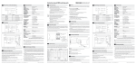
Figure below shows two common types of MBC
(manual boost controller) used on most turbo cars.
NOTE:
The same MAC valve can be used to reduce boost
on any Electronic Boost control valve system. Use
the same hose configuration as the “TYPE 1”,
with Port 2 blocked-off. CEL=OFF (page12.6)
Type 1: pressure from the turbo to the wastegate is
vented to the atmosphere via a restrictor and a vent.
Boost increase is proportional to the amount vented.
When the solenoid valve is energised, pressure
from the turbo is diverted to the wastegate directly. When MBC is by-passed, the boost pressure will drop down to wastegate setting.
Important! install the valve in a dry location with good air flow as the valve is energise continuously.
Only use a valve with low coil power or put a 50W inline resistor to reduce winding temperature.
mac valve
SWITCHED 12V
BR
N/O=3
N/C
2
NC=1
COM=2
NO=3
GROUND
COM=2
NO
WT
mac valve
3-WAY
SOLENOID
VALVE
GREY HARNESS
(DR=OFF)
Supplementary information on HFS-2
The HFS-2 shares the same electronic controller as
in the HFS-3. The only difference is the dash gauge
and flow sensor is not supplied. However, a dash
switch is supplied instead. There is a simple upgrade
kit to HFS-3 available direct from factory.
The design concept behind the HFS-2 system:
Not every application requires a fail safe to reduce
power in the event of a clogged jet or system failure.
In those circumstances, water injection is only used
as a tool to recover power loss due to low fuel
octane and high ambient temperatures. When water
is injected, it will suppress the onset of knock and
lower the intake charge air temperature. The ECU
will not need to retard timing or add fuel to combat
those situations.
The HFS-2 is particularly suitable for countries with
high ambient temperatures. Due to its unique abilities to mirror the fuel duty cycle from as low as 12%
to 100%, this ultra wide dynamic range is perfect for
day to day motoring and occasional power blast.
Another effect could improve the fuel consumption
due to optimum ignition timing is retained as well.
Page 20
The HFS-2 Dash switch:
Other than the on/off
usage of disabling the
system from injecting,
there are three display
modes indicating the status of
the system. A green/red led indicates the system is armed and on
standby by to inject. When the preset trigger point
is reached the green/red led will blink at a steady
rate, informing the user the system is spraying.
When the water tank level drops below the level
sensor probe, the green.red led will change to yellow, Initially it will oscillate between the two colours
until the water is well below the sensor probe, it will
turn solid yellow. At about 20 seconds later, the
system will automatically stop injecting to prevent
air entering the system.
One more useful function, the internal fail-safe relay
works in unison with the status of the dash switch
until the tank is empty or DBH (disabling high boost)
mode is turned off (jumper link removed). This function is making use of the relay whereas lying idle.