1
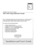
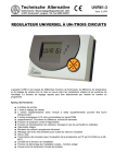
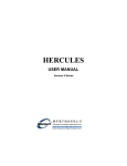
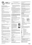
USDT 2004 Installation and User’s Guide Introduction General Information 2 Installation Collector Sensor 3 Control Box 5 Operation Power Connection 6 Operating Display 6 Changing Factory Settings 8 Manual Operation Of Pump 9 Advance Operation 10 Frost and Overheating Protections 12 Energy Calculations Troubleshooting 14 15 Thermo Technologies 9009 Mendenhall Place • Suite E Columbia, Maryland 21045 Phone 410.997.0778 • Fax 410.997.0779 e-Mail [email protected] Revision 4.0, October 2007 Introduction Note: The information supplied in this manual is for guidance only - no part of this may be used for any agreement, whether express or implied, or to form any contract. Thermo Technologies reserves the right to change specifications without prior notice. U SDT 2004 is a powerful temperature differential control unit and may be used in a wide range of applications. The user has the choice of *two modes: Par Mode (access code 32) – This program is USDT 2004's basic program. It uses two sensors to control a simple solar water heating system and factory settings may be altered. Men Mode (access code 64) - This program, initiated by the user, customizes USDT 2004 for applications involving a BTU Meter or where a third sensor (or reference value) is required. *NOTE: USDT 2004 may be used for several advanced applications originating in Men Mode. USDT 2004 has the following functions: • • • • • • • • • 2 inputs for temperature sensors Input for flow rate input or additional temperature sensor BTU meter capability for constant flow rate or with a puls flow meter o o Adjustable (-4 F to 39 F) frost protection o o Adjustable (32 F to 299 F) overheating protection o o Adjustable (1 F to 99 F) temperature difference ?T Manual pump operation Digital display of all parameters System status and diagnostic displays Two - Sensor Operation At its most basic function, USDT 2004 is a two-sensor S1 solar hot water controller. One sensor (S1 in diagram) monitors the collector temperature whilst the other sensor (S2) monitors the temperature at the bottom of the storage tank. The solar loop circulation pump runs while the collector temperature exceeds the tank temperature by an adjustable temperature difference diff. To avoid overheating, the circulation pump stops if the tank temperature (T2) reaches the adjustable high limit (TMAX) temperature. The pump A1 runs only when the temperature at the collector sensor location S1 is higher than the tank temperature at location S2 by at least diff (?T). The pump stops if diff is less than the preset value or, when the temperature at location S2 has reached the TMAX : A1 (ON) only when S1 > (S2 + diff) & S2 < T max A1 S2 The temperature hysteresis (a lagging in the set-point) may over-ride diff to avoid pump cycling. 2 INSTALLATION Note: This installation procedure is for guidance only, and the installer should verify its suitability. Make sure that the solar system is physically installed, manually tested, and ready for controlled operation. T he following safety precautions are strongly recommended: 1. Before attempting to install and operate the unit read this instruction manual carefully. 2. Only suitably qualified personnel should carry out installation and required maintenance. 3. It is recommended that the unit be connected to the power supply via an on/off switch or plug. 4. WARNING: When the unit is connected to the 115-volt power supply and the cover is opened, high voltage circuits will be exposed. When installing the unit, all required connections should be completed and the cover attached to the controller box before turning the power on. Ensure that all connections are secure. If any maintenance work is required isolate the unit from the power supply before removing the cover. Never leave the unit unattended if the cover has been removed and the power supply is connected. 5. Do not exceed unit ratings of 3.15 amps (1/6 HP or 245 Watts pump). 6. It is advisable to route power cables away from sensor cables. S ensor installation: Temperature sensors may be installed in fluid lines by mounting in a well or strapping directly to piping. For the system to function correctly, it is essential that the sensors are located and installed properly. Sensors must be well insulated in order to prevent influence by the ambient temperature. When used outdoors, water must not enter the immersion sleeves. Exposure to moisture (e.g. condensation) can diffuse through the cast resin and damage the sensor. Corrosion-resistant immersion sleeve (sensor pockets) must be used when sensors are used in open loops or swimming pools. l Collector sensor (red cable with protective terminal box): Push into a thermowell, (sensor pocket), which is soldered or riveted directly to the manifold (vacuum tubes). Alternately, strap the sensor to the collector outlet pipe or the absorber (flat plate collectors) that projects from the collector housing. Ideally, house the collector sensor (encased in a suitable sensor pocket) into a T-piece on the collector return outlet. Protect the sensor cable from UV and moisture. 3 l Tank sensor (white cable): This sensor, required for the solar loop return, is installed in the lower part of the storage tank. If there is no provision for this tank sensor, push the sensor beneath the insulation – keeping it close to the inner tank wall at the desired tank location. For external heat exchangers, the tank sensor should be installed with an immersion sleeve in the return leg (cold side) of the heat exchanger. In tanks with integrated heat exchangers, the sensor pocket should be fitted at the exchanger's return to the collector. l Pool sensor installation: Place a heat conductive T-piece on the suction line directly at the pool outlet and screw in the sensor with an immersion sleeve (check corrosion resistance of the material used). Alternately, attach the sensor with clips or adhesive tape, using the appropriate thermal insulation to guard against environmental influences. l Sensor cable extension: Sensor cables (22/4 AWG telephone cable; only two wires of 4) can be extended up to 150 ft. A connection between the sensor and extension can be established as follows: Cut the supplied heat -shrinkable tubing to desired length (about ½ ”). Slide tubing over one end of wire to be sliced (after removing enough outer insulation to accept the tubing). Splice the wire and slide tubing over the splice. Heat gently all around until tubing shrinks tight. Slide larger tubing (about ¾ “) over the entire splice. Heat gently all around until tubing shrinks tight. This connection can then be drawn gently into the pipe work. Only two of the wires are required for the sensor cable; the other two wires are kept spare. Caution: Do not overheat the tubing! Remove heat as soon as the tubing shrinks tight, as material will continue to shrink. With a heat gun or flame source, use an even back and forth motion all around tubing. Let tubing cool for maximum strength. C ontroller unit installation: For viewing comfort, the controller unit should be positioned at eye level. For optimum longevity, avoid extremes of temperature in the placement of electronic equipment. In addition, avoid heavy electrical loads, switches or contactors as these may cause electrical and electromagnetic interference with the unit (when switched on or off). 4 Undo the screw at the top of the housing. The control electronics are mounted on the enclosure cover. The controller enclosure can be screwed to the wall with cable entry grommets pointed downwards. Use the supplied plastic bridges to secure power and sensor cables. Base of the unit to be mounted at eye-level and wired as shown above Caution: Controller wiring should only be done when the unit is not energized. It is possible to damage the control unit if it is assembled under voltage. Miniaturized terminal blocks are used for making wiring connections. The wire is held in place within the terminal with screw that provides excellent contact without damage to the wire. Sensor Cable Connection: Use up to an 18 or 22 AWG stranded wire to connect the sensor cables to the unit. The S1 terminal should be connected to the collector sensor (higher temperature); the S2 terminal is designated for the tank sensor (lower temperature). And the S3 terminal is reserved for the advanced usage of the unit such as a third temperature sensor or flow meter input for BTU operation. 5 P NOTE 1: housing. ower Connections: A small blade screwdriver may be used to fasten miniaturized terminal block screws while the corresponding wire is inserted. Always disconnect the controller from the power supply before opening the NOTE 2: The controller should be properly grounded. Flexible wires, 18/3 AWG (gauge/conductor) simplify connection to the terminals. The power terminal block will accommodate wire sizes up to 14 AWG. All connections should be secured and adequately tightened, as loose power connections will over-heat, and may cause fire. NOTE 3: It is important that the specified output loads (245 Watts) are not exceeded. Where these loads expect to exceed, external relays must be used. It is good practice to install a switch to disconnect the controller and pump from power. Always keep power cables away from sensor cables and other low voltage signal cables. NOTE 4: To protect against lightning damage, the system must be grounded according local regulation. Sensor failures due to the weather or electrostatic are mostly due to poor grounding. OPERATION OF DIGITAL DISPLAY Y Y our controller displays information one request at a time. The unit display window has three lines to inform you about the system's status, unit of displayed parameter and its value. Upper Line Display Symbolic display of sensor location, reading unit, and operation domain Center Line Display Sensor ID and its reading in normal mode (user interface window) Lower Line Display Set-point indicator that illuminates only during programming mode ð Push selection key once to move to the next selection; or increase the selected parameter by one unit while display is blinking. ï Push selection key once to move to the previous selection; or decrease the selected parameter by one unit while display is blinking. 6 ò ñ Push selection key once to enter the advanced (Par or *Men) mode. Once in selected mode, press one more time to select the parameter in that mode. Selected parameter blinks allowing the user to modify it. You can modify the selected parameter while the middle window blinks by pressing the ï or ð key. Push selection key once to accept selection (blinking stops showing the new set-point steady) or go back to the previous selection. * Men mode is for use with advanced applications. Use selection keys ïð during normal system operation to display the desired parameter: T1 xxx T2 xxx T3 xxx G xx XX xxx YY xxx ZZ xxx STAT o Collector temperature in F o Tank temperature in F Reading of the third sensor; if the third sensor displays a fixed reference o temperature of 999 F, the sensor designation can be wrong or the sensor is not connected correctly (open circuit). Flow rate [gallon/h] – programmable by user Collector power in [kW] – amount of energy collector is producing Energy collected in [MWh] Energy collected in [kWh] Display of the system’s status. Any current problems outlined. Example: The following windows display the temperatures of T1 (the collector), T2 (the rd bottom of the tank) and T3 (3 sensor see P.11) At the upper text line, the icon for the text is always displayed. Program symbol is displayed during the setting of parameters at the lower text line Basic Mode (Par): Pressing the selection key ð several times allows you to navigate sensor temperatures and energy output and also access (Par) mode. Push selection key ò once to enter the program mode. Advanced Operations: Pressing the selection key ð several times allows you to enter into the advanced mode (Men). Push selection key ò once to enter the program mode. 7 CHANGING FACTORY SETTINGS: Temperature differentials and manual operation of pump Par Mode is USDT 2004's basic program; it uses two sensors to control a simple solar water heating system. The unit is already factory set with ON/OFF pump temperatures. However, these temperatures may be altered if required: Par Using the navigation key ^_ allows you to select the desired parameter while you are in the program mode. Press the selection key ò once to select the parameter in the window. Selected parameter blinks allowing you to modify it. You can modify the selected parameter while the middle window blinks by pressing the ï or ð key. The unit accepts the new value by pressing the ñ key once. Please make sure that you are in Par mode. RUV 3.5 – Displays the software revision number corresponding to this manual. PR O – Inapplicable PROGRAMMING THE TEMPERATURE RANGE o o USDT 2004 is factory set at approx T2 > 161 F PUMP OFF, T2 < 150 F PUMP ON. Once Par mode has been accessed, using Code 32 as illustrated above, the user may program a different temperature range. There are two temperatures that should be entered: 8 Tank Overheating Protection In Par Mode, user can customize the temperature range by using max? and max=. Use the navigation key ^_ in Par to locate max temperatures and push selection key ò once to make changes: max?1 max=1 Pump stops above tank temperature (T2) Pump runs again below this set point (T2) Temperature Differential Adjustment diff=1 Pump runs when temperature difference between collector T1 (collector) and T2 o (tank) exceeds this value. Factory setting is 15.1 F. Consult your collector manufacturer for the recommended value. diff?1 Pump stops when temperature difference between collector T1 (collector) and T2 o (tank) reaches this value. Factory setting is 7.0 F. Consult your collector manufacturer for the recommended value. Manual Operation of Pump The pump can be manually turned on or off once Par mode has been accessed using Code 32: Automatic mode AUTO Manual ON Manual OFF Use the navigation key ^_ in Par to locate the pump window O AUTO. Push selection key ò once to enter pump operation (ON or OFF). When the manual mode has been selected, an icon (a small icon symbolizing a right hand image) appears under the text line. 9 ADVANCED OPERATIONS or 3 rd sensor designation Men Mode customizes USDT 2004 for applications in conjunction with a BTU meter, a third sensor or reference value. If BTU capability is not required, this program may also, for example, measure the flow rate or the temperature of the storage tank (T3, top of the tank). Men Use the navigation key ^_ to navigate to the Men Window. Use Code 64 to access and program Men mode. Navigation of advanced features of the unit and selection of parameters is the same as before by using ïòñð keys: Advancing – Press the Advance key ïð briefly to advance to the next selection or to increase/decrease the set point of the selected parameter. Hold it down for fast change. Acceptance – Press Set-Up key ò once to select the parameter. Press ñ key to accept the selection or the set point . ENGL – Pre-Set to English. Spanish available in INTER. CODES – 64 for Men Mode. SENSOR : USDT 2004 accepts two different sensor types or a reference value. Press the Advance key ïð briefly until SENSOR appears in centerline and press the key ò. Ensure the reference value reads KTY sensor, all factory supplied sensors are KTY type: U SDT 2004 is extremely powerful. All factory settings can be changed to meet the unique requirements of other applications. All advanced operations have their origin in Men Mode where USDT 2004’s parameters may be altered depending on the application. 10 The factory setting will be retrieved by pressing and holding ò key during powering of the unit. A “WELOAD” displays for three seconds while factory settings are restored. Mode Operation SENSOR SGUARD START AT ALARM BTU Selects sensor type Protects system from overheating and frost Starts pump at pre-set insolation (solar radiation intensity) After-running time. Factory-set at 0. Enables/Disables protection functions Energy calculation and setting S ensor Designation – USDT 2004 accepts two different sensor types or a reference value . User can program a constant reference temperature instead of a sensor output. The factory-preset sensor is the thermistor (KTY 10) type. The KTY 10 tank sensor, white wire, should be used in a conditioned environment and will not be permanently damaged up o to 360 F. Selection: S1 S2 S3 Sensor 1 (collector outlet) selection Sensor 2 (collector inlet) selection Sensor 3 (tank) selection Designation: PT KTY GBS (S3(-S 1 DIG OFF VSG o PT 1000 sensor (1000 O at 0 C, not available in US market) o Thermistor sensor (2000 O at 25 C) Radiant sensor (not available in US market) Fixed value, the unit uses this value instead of measured temperature Transfer of values (not used in program 0 operation) Digital input (not used in program 0 operation) The sensor reading is not displayed Flow rate reading Sensor wires can receive electromagnetic pulses, which can result in a wrong temperature reading. The USDT 2004 reads sensor values every 50 ms. It can bundle several readings and process their average. AV 1 AV 2 AV 3 Sensor 1 average Sensor 2 average Sensor 3 average The numbers of samples can be programmed from 4 to 20. 11 F rost and overheating protections - Pump operation can be manipulated by the user in both collector stagnation and frost conditions. This set-up is possible in System Guard, SGUARD, Men domain. Overheating protection (CET) – The Circulation pump may not be powerful enough to circulate the heat transfer fluid in the solar loop with air pockets. User can program the pump to stop at a desired maximum collector temperature, shown by ? symbol, to protect the pump. USDT 2004 will take over the normal operation after the temperature decreases to an acceptable working temperature, shown as =. This feature (ON) can be disabled by user to (OFF). Factory setting o o is 260 F to stop the pump. The pump starts again at 230 F. Customer in field can change these settings. Frost Protection – Frost protection in the sun-belt region is provided by circulating water in the solar loop when freezing conditions exist. Regardless of the temperature difference ? T, the circulation pump runs when the collector temperature is below a programmable minimum temperature, shown by = symbol. The pump stops as soon as the temperature in the solar loop reaches a safe region programmed by the ? symbol. This feature is disabled at the factory and displayed as (OFF). min= min? Pump runs below this temperature (factory setting 35 F) Pump stops above this temperature (factory setting 39 F) S tart functions - The Circulation pump can be programmed to start on a low insolation level. The Start function feature is useful when heat transferred to the collector sensor is not fast enough for an early start; especially when the collectors are flat mounted. The enabled start function runs the pump at a given solar radiation or programmed temperature difference. The feature is disabled at the factory. START ON OFF Start function screen Enable start function Disable start function If this feature is selected, following parameters must be adjusted for proper operation: GBS Pyranometer port designation (radiation monitoring sensor port) 1 Sensor 1 2 Sensor 2 3 Sensor 3 -Manual input in next step 2 Radiation threshold in W/m Pump runtime in seconds Maximum interval time in second Number of flushes INS CIRC INT FLU 2 The following example activates the circulation pump at 200 W/m and runs it for 15 seconds. If rT condition is met within the time period, the pump stays on. INS 20 CIRC 15 12 After-running time AT – During the start phase, the pump may repeatedly switch on and off for a long time, especially systems with long solar loop. The after-run time AT can be changed from 0 (factory setting) to 9 minutes. A larm functions - User can enable the alarm function of the USDT 2004 in the ALARM screen. Status of sensors and circulation pump can be viewed if alarm function is active. A ON A OFF Alarm function enable Alarm function disable The status of the system can be monitored in the Stat Mode only if the corresponding feature is active. The following example shows a system condition with a circulation problem: CET OFF CET ON 1 SHORT 2 SHORT 1 OPEN 2 OPEN OK NO CIRC OK CIRC CLEAR Collector excess temp. cut-off active (no error occurred) No overheating Short circuit in sensor 1 wiring Short circuit in sensor 2 wiring Disconnection in sensor 1 wiring Disconnection in sensor 2 wiring System operates normal o r T is more than 108 F in last 30 minutes Pump is running Clears NO CIRC display after correction 13 E nergy calculation - Energy gain is calculated by obtaining the temperature increase of the heat transfer fluid as it crosses the solar collector. The amount of fluid flow through the collector is registered by an in-line flow meter. USDT 2004 computes the energy production as a function of the temperature differential and fluid volume. In addition, the system anti-freeze (Glycol) percentage should be entered as it affects the thermal conductivity and heat transfer rate. BTU S IN S OUT F SEN Energy calculation mode Sensor port selection for inlet temperature (1, 2, 3, --) outlet temperature (1, 2, 3, --) Sensor port selection for flow rate (1, 2, 3, --) Energy calculation will be initiated only after temperature sensor ports are designated. Flow rate can be either a constant number to be entered by user, or from a flow meter input. To activate the energy calculation without using the flow meter's impulse input, a dash (-) must be selected for F SEN channel followed by the constant flow rate in gph (gallon per hour) unit: GAL Constant flow rate in gph instead of flow meter reading in (--) sensor mode Select 3 for F SEN when a flow meter is used: LPP GLYCOL DIF (- Flow meter rate impulse number in liter per pulse, if flow meter is used Anti-freeze percentage Sensor calibration The output of USDT 2004 unit is kW for system power and kWh or MWh for collected energy. The energy calculation dependents on flow meter accuracy, the temperature sensors class, and their locations. The flow meter is a mechanical device and its accuracy fluctuates over time. Therefore, the user should calibrate the flow meter and incorporate temperature sensor tolerance. o The supplied Thermistor sensor has an accuracy of ± 2 F. DIF represents the temperature difference between two sensors. User can increase the accuracy of reading by adjusting the DIF parameter. To calibrate the system, insert both S IN and S OUT in the same temperature (such as ice-water glass), DIF should show “DIF 0” for exact temperature reading. If it is not zero, accept the difference for better accuracy. This difference will be used as a correction value for energy calculation. The energy calculation becomes more accurate at temperature range that this reading adjustment is made. BTU CL CLEAR Sets the BTU meter's counter to zero BTU meter's counter is zero 14 T roubleshooting In general, if there is a malfunction all of the settings in the menus Par and Men and the terminal should first be checked first. Malfunction, but "realistic" temperature values: • • • • • • Check program number. Check the switch-on and switch-off thresholds and the set differential temperatures. Have the thermostat and differential thresholds already been reached? Were the settings in the submenus (Men) changed? Can the pump (output) be switched on and off in manual mode? If a forced pump “ON” and “OFF” lead to the appropriate reaction at the output, the unit is certainly in order. Are all of the sensors connected with the right terminals? Heat up the sensor using a cigarette lighter and watch the display. Did you change the reference temperature 250 (three sensor operation) to KTY? Incorrect display of temperature(s): • • • Displayed values such as -999 if a sensor short-circuits or 999 if there is an interruption do not necessarily mean a material or terminal error. Are the right sensor types (KTY or PT1000) selected in the menu Men under SENSOR? The factory settings set all inputs to KTY. The sensor can also be checked without a measuring instrument by connecting the presumed defective sensor to a terminal that works and checking the display. The resistance measured by an ohmmeter should have the following value depending on the temperature: T R(KTY) 0 1630 10 1772 20 1922 25 2000 30 2080 40 2245 50 2417 60 2597 70 2785 80 2980 90 3182 100°C 3392 Ω The settings of the parameters and menu functions ex works can be restored any time by pressing the down arrow (enter) while powering the controller. The sign that appears for three seconds on the display is RESTOR for load factory settings. If the system is not in operation while connected to the power supply, the 3.15A quick-blowing fuse that protects the control system and the output should be checked and exchanged if necessary. As the programs are constantly being improved, there may be a difference in the sensor, pumps, and program descriptions. Only the enclosed manual (identical serial number) applies for the equipment supplied. The program version for the manual must correspond to the equipment version. If the control system is found to be malfunctioning despite the checks described above, please contact your retailer or Thermo Technologies directly. The cause of the error can only be determined if the settings of the unit is known. The schematic diagram of the system in question is a great help to isolate the potential problem. 15