1
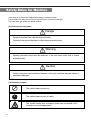
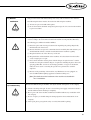
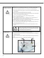
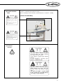
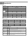
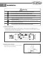
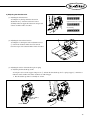
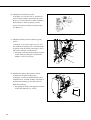
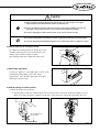
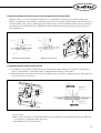
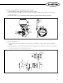
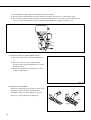
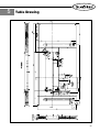
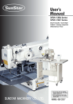
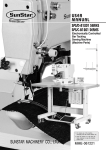
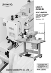
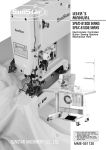
R
User’s
Manual
KM-570BL
1 needle, drop feed,
needle feed sewing machine
KM-570BL-7
1 needle, drop feed,
needle feed sewing machine
with automatic thread trimmer
KM-572BL
2 needle, drop feed,
needle feed sewing machine
KM-572BL-7
2 needle, drop feed,
needle feed sewing machine
with automatic thread trimmer
1) For proper use of the machine, thoroughly
read this manual before use.
SUNSTAR MACHINERY CO., LTD.
2) Keep this manual in a safe place for future
reference in case the machine breaks down.
MME-060710
lity
a
u
tQ
Besst Pricevice
Be st Ser
Be
1. Thank you for purchasing our product. Based on the rich expertise and
experience accumulated in industrial sewing machine production, SUNSTAR
will manufacture industrial sewing machines, which deliver more diverse
functions, high performance, powerful operation, enhanced durability, and
more sophisticated design to meet a number of user’s needs.
2. Please read this user’s manual thoroughly before using the machine. Make
sure to properly use the machine to enjoy its full performance.
3. The specifications of the machine are subject to change, aimed to enhance
product performance, without prior notice.
4. This product is designed, manufactured, and sold as an industrial sewing
machine. It should not be used for other than industrial purpose.
R
SUNSTAR MACHINERY CO., LTD.
Table of contents
Safety Rules for Machine .......................................................................................................................................... 4
1. Specification ............................................................................................................................................................... 8
1) Sewing machine ............................................................................................................................................................. 8
2) Motor .............................................................................................................................................................................. 8
3) Peripheral automation devices (optional) ..................................................................................................................... 8
2. Installation ................................................................................................................................................................... 9
1) Installation of machine head ......................................................................................................................................... 9
2) Installation of power switch box ................................................................................................................................... 9
3) Oil supply ..................................................................................................................................................................... 10
4) Belt tension adjustment ............................................................................................................................................... 10
5) Installation of program unit (Trimmer Type) .............................................................................................................. 11
6) Installation of belt cover .............................................................................................................................................. 11
7) Installation of thread stand .......................................................................................................................................... 11
8) Installation of knee lifting pad .................................................................................................................................... 12
9) Installation of air pressure related parts and checking their functions (optional) ..................................................... 12
3. Adjustment of the Machine ............................................................................................................................. 13
1) Inserting the needle ...................................................................................................................................................... 13
2) Removing bobbin ........................................................................................................................................................ 13
3) Winding the lower thread ............................................................................................................................................ 14
4) Routing the upper thread ............................................................................................................................................. 14
5) Adjusting the thread tension ........................................................................................................................................ 15
6) Adjusting the tension of the presser foot .................................................................................................................... 17
7) Stitch length adjustment .............................................................................................................................................. 17
8) Adjusting timing of needle and hook .......................................................................................................................... 17
9) Clearance adjustment between hook and opener ....................................................................................................... 18
10) Adjusting feed dog height ......................................................................................................................................... 19
11) Adjusting the auxiliary presser foot and the upper feed presser foot ...................................................................... 19
12) Adjusting timing of the auxiliary presser foot, the upper feed foot and the needle ................................................ 21
13) Adjusting stroke of upper feed presser foot .............................................................................................................. 21
14) Adjusting safety device ............................................................................................................................................. 22
15) Adjusting the trimming device .................................................................................................................................. 22
16) Adjustment of Thread Release .................................................................................................................................. 25
17) Installation of Automatic Lap Lifting Device (optional) ......................................................................................... 25
4. Causes of Troubles and Troubleshooting ............................................................................................... 27
1) Sewing machine troubleshooting ................................................................................................................................ 27
5. Table drawing ......................................................................................................................................................... 29
Safety Rules for Machine
Safety labels in the manual are categorized into danger, warning and caution.
Failure to follow the safety rules may result in physical injuries or mechanical damages.
The safety labels and symbols are defined as follows.
[The meaning of the safety labels]
Danger
Danger Instructions here shall be observed strictly.
Otherwise, the user will be killed or suffer severe physical injuries
Warning
Warning Instructions here must be observed, or the user could suffer fatal or severe
physical injuries.
Caution
Caution Instructions here should be observed, or the user could face physical injuries or
mechanical damages.
[The meaning of symbols]
This symbol means a must-not.
This symbol means a must for safety.
This symbol means that an electric shock may be caused if the
instruction is not followed properly.
4
1-1) Machine
mobilization
Only personnel with a full understanding of the safety rules should move the machines.
The following directions must be observed when delivering the machines.
ⓐ At least two persons should work together.
ⓑ In case the machine should be transported, please wipe the oil covered on the machine
to prevent accidents
Danger
1-2) Machine Installation
Caution
Because physical damage such as the functional obstacles and breakdowns are likely to
occur according to the environment in which the machine is being installed. Therefore,
the following preconditions should be fulfilled.
ⓐ Please keep the order from top to bottom when unpacking the package. Especially,
mind that the nail on the boxes.
ⓑ Because machines are apt to be contaminated and corroded by dust and moisture, you
should install the climate controller and should clean the machines regularly.
ⓒ Keep the machines out of the direct rays of the sun.
ⓓ Keep both sides and the backside of the machines off at least 50cm from the wall to
secure enough space to repair.
ⓔ Don’
t run the machine near the places with the dangers of explosion. Don’t run the
machine near the places with the dangers of explosion, including the places where the
spraying product like aerosol are used in large quantities or oxygen are dealt with,
unless the exact actions concerning the operation are guaranteed to avoid the
explosion.
ⓕ Because of the peculiarity of the machine, any illuminators are not equipped. So,
users should install the lighting apparatus around the working area.
[Note] The details about the installment of the machine are described in
No. 2 Installations.
1-3) Troubleshooting
Danger
In need of troubleshooting, it should be done by the trained A/S engineer of our company.
ⓐ Ahead of cleaning and repair, be sure to shut off the power supply. And wait for about 4
minutes till the machine discharges completely.
ⓑ Even a part or all of the machine should not be modified without any consultation with
our company.
ⓒ In case of repair, you should change the damaged part into the standard article of our
company.
ⓓ After repair, please put again the safety cover disjointed while repairing.
5
1-4) Machine Operation
Warning
KM-570/572 series are manufactured for industry use to sew textiles and other similar
material. In case of running the machine, users should observe the following things.
ⓐ Ahead of operating the machine, please read the manual and understand fully the details
on its operation.
ⓑ Don’t forget to put on the garment suited for the safe work.
ⓒ Keep your hands or a part of the body away from the running part of the machine like a
needle, hook, thread take-up spring and pulley etc.
ⓓ Don’t remove any kind of cover for safety while running the machine.
ⓔ Be sure to connect the earthed line.
ⓕ Before opening the electric box such as a control box, be sure to shut off the power
supply and make sure that the power switch should be put on“off.”
ⓖ When threading the needle or before checking after sewing, be sure to stop the machine.
ⓗ Don’t switch on the power supply with the foot on the pedal.
ⓘ Don’t run the machine when the cooling fan are not running. Be sure to clean the air
filter in the control box once a week.
ⓙ If possible, keep off from the strong electronic wave like a high frequency welding
machine.
Warning
1-5) Safety Device
Warning
Always start the machine with safety covers in place since fingers
or hands could be injured or cut off by the belt. Turn off the power
switch during check-ups or adjustments.
ⓐ Safety Label: Suggestions while running the machine are stated.
ⓑ Thread take-up spring cover: the device to prevent the human body from touching the
thread take-up spring.
ⓒ Belt cover: the device to prevent hands, feet and clothing from getting jammed by the
belt.
ⓓ Finger guard: the device to prevent fingers from contacting the needle.
ⓐ
ⓑ
ⓒ
ⓓ
6
1-6) Position of Caution
Mark
CAUTION
경 고
“Caution”is attached to the machine for safety.
In case of starting to run the machine, read the directions of“Cautions”carefully.
[Position of Caution Mark]
Do not operate without finger guard and
safety devices. Before threading, changing
bobbin and needle, cleaning etc. switch off
main switch.
손가락 보호대와 안전장치 없이 작동하지
마십시오.
실, 보빈, 바늘교환시나 청소전에는 반드시 주
전원의 스위치를 꺼 주십시오.
CAUTION
경 고
Hazardous voltage will cause injury.
Be sure to wait at least 360 seconds before
opening this cover after turn off main switch
and unplug a power cord.
고압 전류에 의해 감전될 수 있으므로 커버를
열 때는 전원을 내리고 전원 플러그를 뽑고 나
서 360초간 기다린 후 여십시오.
1-7) Content of
“ Caution”
”
Caution
CAUTION
경 고
Do not operate without finger guard
and safety devices. Before threading,
changing bobbin and needle, cleaning
etc. switch off main switch.
손가락 보호대와 안전장치 없이 작동하지
마십시오.
실, 보빈, 바늘교환시나 청소전에는 반드시
주전원의 스위치를 꺼주십시오.
CAUTION
경 고
Hazardous voltage will cause injury.
Be sure to wait at least 360 seconds
before opening this cover after turn
off main switch and unplug a power
cord.
고압 전류에 의해 감전될 수 있으므로 커버를
열 때는 전원을 내리고 전원 플러그를 뽑고
나서 360초간 기다린 후 여십시오.
7
1
Specification
1) Sewing machine
Category
KM-570BL-7
Purpose
Lubrication Method
Max. Sewing Speed
Max. No. of Stitches
Needle Stroke
Manual
Presser Foot
Lap
Lift
Automatic
16mm (optional)
Crossing Between Upper Feed Presser
Foot and Supplementary Presser Foot
For Heavy Materials (sheet, bags, tents, sofas, etc.)
Automatic Lubrication
2,000spm
9mm
36mm
10.5mm
16mm
-
16mm (optional)
KM-572BL
-
2~6mm
Hook
Needle
Automatic Backtacking Device
Automatic Trimmer
Bed Size
Basic Supply
Basic Supply
Horizontal 2.5x Hook
DP×17 #23 (#14~#25)
Basic Supply
-
Basic Supply
-
-
-
568×178mm
1-phase 110/220V,
3-phase 220V
Power Supply
KM-572BL-7
KM-570BL
1-phase 110/220V,
3-phase 220V/380V
1-phase 110/220V,
3-phase 220V
1-phase 110/220V,
3-phase 220V
2) Motor
① Servo motor controller
MODEL
VOLT
WATT
HERTZ
SC55-1B
1 Phase 110V
550W
50/60 Hz
SC55-1B
1 Phase 220V
550W
50/60 Hz
SC55-3B
3 Phase 220V
550W
50/60 Hz
MODEL
VOLT
WATT
HERTZ
HEC-1706(1 Phase)
110/220V
400W
50/60 Hz
HEC-1705(3 Phase)
220/380V
400W
50/60 Hz
② Clutch motor
3) Peripheral automation devices (optional)
Optional device
Model
AUTO KNEE LIFTING
SYSTEM
8
Usage
When the pedal is placed at reverse step 1, the presser foot is automatically lifted. It is because the
machine has employed the pneumatic cylinder structure.
PRODUCTION
COUNTER
SCOUN-1
A counting device which indicates the completed quantity on the program unit panel, including added,
subtracted, corrected or remaining quantity along with other performance rates.
MATERIAL EDGE
SENSOR
SEDG-1C
SEDG-2C
A device that senses the edge or thickness of the sewing material to stop the machine without manual
pedaling. Available in two types: SEDG-1C for edge sensing type and SEDG-2C for thickness sensing
type.
STANDING PEDAL
SPDL-1
SPDL-2
An essential device when one person is operating multiple sewing machines. Has different pedals for
acceleration, thread trimming, presser foot and ascending pedal. Types consist of SPDL-1 for fixed
speed and SPDL-2 for variable speed.
2
Installation
Warning
▶ In case of installing the machine, it should be performed by the trained engineer.
▶ In case of wiring work, be sure to leave the work to an expert or an agent.
▶ The machine weight over 42kg. At least 2 persons should carry out the installing work.
▶ Plug in after finishing the installing work. In case the user press on the step by mistake, the
machine runs automatically. By doing so, it can cause the physical injuries.
▶ Connect the earthed lines.
Imperfection of the connection of the earthed lines gives rise to an electric shock or malfunction.
▶ Set the belt cover on top of the machine.
▶ In case of bending the machine backward or returning to the original condition, be sure to use
both hands. If you use only one hand, it causes physical injuries by slipping.
1) Installation of machine head
※ Insert hinge rubber① into the table. As described in“Figure 1”, put the oil pan corner in the middle of the head
supporting rubber② and attach the table. After putting the hinge ③ in the bed hole, insert the hinge rubber① and install
the sewing machine in the table corner rubber cushion.
③
①
②
④
[Figure 1]
2) Installation of power switch box
When attaching the power switch box①, as shown in “Figure 2”,
attach it to lower right corner of the table.
①
[Figure 2]
9
Caution
▶ Be sure to plug in after finishing oil supply.
If the user press on the step by mistake, the machine runs automatically. By doing so, it can
cause the physical injuries.
▶ In case of treating the lubricant, don't bring the lubricant into contact with eyes or the skin. Its
contact can cause an inflammation. And don't drink the lubricant. It can cause vomiting or
diarrhea. And Keep it out of the reach of the children.
▶ Be sure to run the machine after supplying oil in case you should start to run it for the first time,
or in case it has not been used for a long time.
3) Oil supply
(1) Fitting the magnet to remove chips (iron powder).
Find the magnet for chip removal① in the accessory box and attach it to the oil pan as in “Figure 3.”
※ Do not use the magnet for other purposes. Operating the sewing machine without the magnets may cause malfunction
and adverse effects to its durability.
(2) Filling the oil pan with lubricants
A. Fill the lubricant up to the“H” point.
B. You should use the exclusive oil provided by“SUNSTAR” for industrial sewing machines or TELLUS C10” of the
Shell company.
C. If the oil lever drops to the“L” level, replenish it to the“H” point.
D. Change the lubricant once every two weeks.
①
[Figure 3]
4) Belt tension adjustment
After installing the motor, if you sufficiently loosen the
fixed nuts ① and ②, tension in the belt④ will occur
naturally because of the weight of the motor③. At this
moment, tighten the fixed nut① and use fixed nut ② to fix
it firmly. (See figure 4)
④
②
③
①
[Figure 4]
10
5) Installation of program unit (Trimmer Type)
A. Use 4 fixed screws③ to fix the bracket ② on the
program unit①
B. In the program unit①, use two fixed bolts ④ to tightly
fix the assembled brackets②.
③
①
②
④
[Figure 5]
6) Installation of belt cover
A. Set the groove at the bottom of belt cover“A”① to be
aligned with the groove of the head of the belt cover
supporting screw②, and insert the cover into the groove.
Use the belt cover fixing screws ③ (2EA) to fix the
cover to the body of the machine.
B. Insert the belt cover“B”② into the belt cover“A”①
while maintaining the balance. Use the belt cover fixing
screws (3EA) to fix the belt covers to the body of the
machine.
④
②
③
①
[Figure 6]
7) Installation of thread stand
As shown in“Figure 7”, assemble the thread stand①,
insert it in the table hole, and use the fixed nut② and
washer③ to fix it.
②
③
①
[Figure 7]
11
8) Installation of knee lifting pad
A. Find the lap lifting pad (ass'y) ① in the accessory box
and insert it into the shaft of the oil pan's control body
②.
B. Loosen bolt ③ and maintain knee-lifting pad in vertical
position to tighten it.
①
②
③
[Figure 8]
9) Installation of air pressure related parts and checking their functions (optional)
Caution
▶In need of regulating the machine with the switch on or with the air injected, please pay special
attention to your safety.
▶Please adjust air pressure to 0.5Mpa.
(1) Installation
As shown in the figure, after fixing the air pressure filter
on the bracket, use the neck screw to fix the bracket on
the lower side of the table.
(2) Air pressure adjustment
a) Adjust the pressure by taking out and lifting the air
pressure filter① knob ② .
b) After adjusting the air pressure to. 0.49㎫(5㎏f/㎠)
turn the knob ② to its original position and the
adjustment is over.
②
①
[Figure 9]
12
3
Adjustment of the Machine
Caution
▶In case of setting the needle, be sure to switch off the power supply. In case the user press on the
step by mistake, the machine runs automatically. By doing so, it can cause the physical injuries.
▶In case of using the clutch motor, the motor revolves because of inertia for a while even after switching
off the power supply. Be sure to start to work only after the motor comes to a complete stop.
1) Inserting the needle
As in Figure 10, while the needle groove① is headed inward, place the upper end of the needle to closely contact the upper
stopper hole②, and then fix the needle by using the fixing screw③.
②
③
③
①
③
②
[ KM-572 BL ]
[ KM-570 BL ]
[Figure 10]
2) Removing bobbin
Place the needle ① in the highest position.
As in Figure 11, open the sliding plate② and erect the hook③ and the bobbin holder④ to separate the bobbin⑤ (see Figure
11).
④
③
①
②
⑤
[Figure 11]
13
Caution
▶In case of adjusting the tension of the lower thread, be sure to switch off the power supply.
If the users press on the step by mistake, the machine runs automatically. By doing so, it can
cause the physical injuries.
▶In case of using the clutch motor, the motor revolves because of inertia for a while even after
switching off the power supply.
3) Winding the lower thread
Insert the bobbin ② into the hook ①. As seen in Figure 12,
insert the thread through part of the hook and pull it out
from the end of the lower thread tension adjustment plate
③. And then pull the thread through the clearance ⑤
between the hook ① and opener ④. The adequate length of
the pulled-out lower thread on the slide plate is 50 mm.
Lower
thread
About 50 mm
②
①
④
⑤
③
[Figure 12]
Caution
▶In case of taking up the upper thread, be sure to switch off the power supply.
If the users press on the step by mistake, the machine runs automatically. By doing so, it can
cause the physical injuries.
▶In case of using the clutch motor, the motor revolves because of inertia for a while.
Be sure to start to work only after the motor comes to a complete stop.
4) Routing the upper thread
Place the thread take-up lever to the highest position and
hang the upper thread as in Figure 13.
※ The adequate length of upper thread extending from the
needle hole is 50 mm for initial sewing.
50m
m
[Figure 13]
14
5) Adjusting the thread tension
Upper thread tension is weak
(1) Adjusting the thread tension
As in Figure 14, turning clockwise the tension
adjustment nut ① of the thread tension control
assembly makes the upper thread tension stronger and
counter clockwise makes it weaker.
Upper thread tension is strong
Good sewing
①
[Figure 14]
(2) Adjusting the lower thread tension
As in Figure 15, turning the tension adjustment screw
① of the hook clockwise makes the lower thread
tension stronger and counterclockwise makes it weaker.
①
[Figure 15]
(3) Adjusting the tension of thread take up lever spring
A) Adjusting the thread take up stroke
As in figure 16, loosen the stopper clamp screw ③, and turn the thread take up lever’s spring stopper ① clockwise to
make the stroke smaller and counter clockwise to make it bigger.
※ The thread take up stroke is normally 10~14 mm.
Bigger
③
②
②
Smaller
[Figure 16]
15
B) Adjusting the thread take up tension
As in figure 17, loosen the screw ② of the thread
tension control assembly, and insert the driver into
the groove of the thread tension control assembly ③.
Turn clockwise to make the spring ① tension
stronger and counter clockwise to make it weaker.
(See Figure 17)
③
Strong
Weak
②
①
[Figure 17]
C) Adjusting the timing of the thread take up spring
tension
As in Figure 18, loosen the stopper screw ①, and
turn clockwise the guide plate ③ for the thread take
up spring to make the timing of the spring ② faster
and counter clockwise to make it slower.
※ The timing of the thread take up spring tension is
normal, when the guide plate is located in the
middle as can be seen in figure.
①
②
③
[Figure 18]
D) Adjusting the auxiliary thread tension control
assembly (for automatic trimming type)
As in Figure 19, when the auxiliary thread tension
adjustment nut ① is turned clockwise, the length of
the thread after trimming is short. The other way
makes the thread long.
※ The appropriate length of the upper thread on the
needle after trimming is 35~45 mm.
①
35~45mm
[Figure 19]
16
Caution
▶After finishing dismantling or adjusting the safety devices, be sure to install it in the original
position properly and check whether it functions as desired or not.
▶In case of bending the machine backward or returning to the original condition, be sure to use
both hands. If you use only one hand, it can cause the physical injuries by slipping.
▶In case of adjusting the machine with the switch on, be sure to see that all is right.
▶In case of troubleshooting or checking the machine, it should be performed by the trained engineer.
▶In case of repair and checking related to electricity, be sure to leave the work to an expert or an agent.
6) Adjusting the tension of the presser foot
①
As in Figure 20, turning the pressure adjustment screw ①
clockwise makes the presser foot tension stronger, and
turning counter clockwise makes it weaker.
After adjusting, make sure to tighten the fixing nut ②.
Weaker
Stronger
②
[Figure 20]
7) Stitch length adjustment
As shown in“Figure 21”, the numbers that are shown in the
stitch length adjusting dial① are the stitch length
represented in“mm”. Find the stitch length you want by
adjusting it from left to right.
①
[Figure 21]
8) Adjusting timing of needle and hook
(1) Fixing the height of the needle bar
※ Turn the pulley to make the needle bar be placed in its lowest position. Loosen the needle bar holding screw① in
Figure 23 to make sure that the needle bar carved sign ⓐ meets the end ⓑ of the frame, then tighten the screw.
ⓐ
ⓑ
The needle bar in the
lowest position
①
[Figure 22]
[Figure 23]
17
(2) Adjusting the timing of hook edge and needle center crossing
First, set the stitch length at“0”. Adjust the hook gear clamp screw ① in Figure 25 so that the hook edge fall exactly at
the center of the needle center when the needle bar is raised 2.4 mm from its lowest position as in Figure 24. When this is
done, the hook edge will be placed at about 1.5 mm above from the front of the needle thread hole.
③
①
①
①
②
[Figure 25]
[Figure 24]
(3) Adjusting the distance between the needle and the hook edge
Raise the needle from its lowest point so that the hook edge meets the needle center. As in Figure 26, when the lower part
of the needle meets the balance point of the hook’s needle guide plate ① (adjust the needle guide form), adjust the
distance between the hook edge and the inner side of the needle groove to 0.05~0.1 mm. Loosen ①, ② and ③ in Figure
27 and move the hook base ④ to the left and right for adjustment. (After adjustment, fasten ①, ② and ③ firmly.)
Hook edge
Needle
④
③
Adhering part
①
①
②
①
0.05~0.1mm
[Figure 26]
[Figure 27]
Loosen the opener clamp screw ③ and turn the opener ② to
the right and left so that the distance between the hook ①
and the opener ② is about 0.2mm as in Figure 28 when the
opener ② is pulled to its max towards the arrowed direction.
0.
2m
m
9) Clearance adjustment between hook and opener
①
③
②
[Figure 28]
18
10) Adjusting feed dog height
Turn the pulley so that the feed dog ① is positioned at its hight to adjust the feed dog ①. Loosen the fork clamp screw ④ of
the feed dog base as in Figure 29 and move the feed dog base up and down so that the feed dog protrudes about 1 mm from
the needle plate top. After adjustment, fasten the clamp screw ④ firmly.
About 1 mm
③
①
②
④
[Figure 29]
11) Adjusting the auxiliary presser foot and the upper feed presser foot
※ Both the auxiliary presser foot and the upper feed presser foot move up and down.
※ It is normal that both of them move up and down to the same height.
※ Take the following steps either to adjust the stroke of both to be the same or to make one of the two adjusted lower or
higher, depending on sewing materials.
(1) Adjusting the strokes of both to be the same
②
①
Increase
6mm
6mm
Decrease
③
[Figure 30]
A) The vertical motion range of the supplementary presser foot① and the upper feed presser foot② is 2~6mm.
B) Loosen the adjusting hinge screw ③.
C) Vertically adjust the hinge screw③ depending on sewing fabric. When the motion range is set large, move the
adjusting hinge screw③ upward. Otherwise, move the adjusting hinge screw downward.
19
(2) Adjusting the height of the strokes of both different
④
①
10.5mm
⑥
②
⑤
③
[Figure 31]
Adjusting the auxiliary presser foot
※ Loosen the pressure-adjusting screw ④ and the bracket-fastening screw ⑤.
※ Adjust the bracket-fastening screw ⑤ so that the auxiliary presser foot① rise about 10.5 mm from the needle plate
top when the pressure lifter ③ is raised.
(After adjustment, be sure to fasten the bracket-fastening screw ⑤ first, and then adjust the pressure-adjusting
screw ④.)
※ Affter the adjustment of the height of the auxiliary presser foot①, adjust the upper feed presser foot②.
Adjusting the upper feed presser foot
※ Loosen up and down crank clamp screw ⑥ when the pressure lifter ③ is down.
※ Move the needle bar close to its highest position.
※ Adjust the height of the upper feed presser foot② to the sewing materials.
20
12) Adjusting timing of the auxiliary presser foot, the upper feed foot and the needle
When the needle ① goes down, the upper feed presser foot ③ should adhere to the feed dog ② before the needle edge
adheres to the upper part of the feed dog ②. The upper feed presser foot ③ should continue to adhere to the feed dog ② even
when the needle ① edge, going up, and the upper part of the feed dog ② are detached with each other. If not, loosen the two
up-and-down cam ⑤ clamp screws ④ to adjust right and left the fixed position of the up-and-down cam ⑤ of the presser
foot. (See Figure 32)
①
③
④
⑤
②
When the needle goes down
When the needle goes up
[Figure 32]
13) Adjusting stroke of upper feed presser foot
(1) As in Figure 33, the machine is adjusted to have the same amount of upper feed presser foot stroke ④ as the feed dog
stroke ⑤. (The baseline ⑥ of the shake crank ③ is aligned with the baseline ⑦ of the collar.)
(2) Take the followings steps, if the two base lines are not aligned or if it is necessary to adjust the stroke ④ of the upper feed
presser foot to increase or decrease.
④
Upper feed
③
②
①
⑦
⑥
Lower feed
⑤
[Figure 33]
Loosen nut ①.
Move nut ① to the back ② of the horizontal roller to increase the stroke ④ of the upper feed presser foot. Move nut
① to the front ③ of the shake crank to decrease it.
After adjustment, be sure to fasten nut ①.
21
14) Adjusting safety device
If the load occurs by foreign substances on thread, needle, etc, during the sewing operation, the driving ball ① of safety
assembly in Figure 34 is removed to prevent damage of the hook and other major parts from the lood, and the pulley ② and
the clutch plate ③ on the safety assembly are removed. Then, the driving force of timming belt on the upper shaft does not
delivered to the lower shaft, so only the pulley ② of safety assembly rotates idly. In case that the safety assembly starts
operating during the work, turn power switch off and remove causing factors of load. Later, with safety button ④ pressed,
turn the pulley to place the driving ball① of safety assembly to its original position.
※ Adjust the intensity of the safety assembly spring ⑤ by rotating safety assembly adjustment screws ⑥ from side to side
in accordance with working conditions. (Turning the screw to left makes the intensity stronger, and right to make it
weaker. Make sure to give same pressure on the three screws.)
③
⑤
⑥
④
⑥
①
②
[Figure 34]
15) Adjusting the trimming device
(1) Adjustment of Initial Position of Moving Blade
Loosen the tightening screws ①,② for trimmer crank, and set the slant end of the moving blade③ to protrude 0~0.5mm
from the fixed blade④. Then fasten the tightening screws①,② for trimmer crank.
①
0~
0.
5m
m
③
④
②
[Figure 35]
22
(2) Distance Adjustment Between Moving Blade and Hook Stopper
A) Turn the pulley by hand to place the needle bar at the lowest position.
B) Press the trimmer driving link① with the needle at the lowest position. Turn the pulley until the moving blade②
reaches to the end.
C) Loosen the screws ③, ④ to set the distance between the moving blade and the hook stopper at 0.5mm.
③
②
④
①
0.5mm
[Figure 36]
(3) Adjustment of Trimmer Cam
A) Set the distance between the oil pump① and the trimmer cam bushing② at 34mm, and then fasten the tightening
screw③.
B) Place the trimmer cam④ to closely contact the end of the bushing. Place the thread release cam⑤ to closely contact
the end of the trimmer cam, and then fasten the screw.
④
③
34mm
⑤
②
①
[Figure 37]
23
C) Turn the pulley by hand to place the needle bar at the lowest position.
D) Press the trimmer driving link⑥ to insert the trimmer cam roller⑦ into the groove of the trimmer cam④.
E) Turn the pulley by hand to make the needle ascend 5mm from the lowest position. Then loosen the trimmer cam
screw⑧ to enable the adjustment of the moving blade. When adjustment completes, fasten the screw.
⑥
⑦
④
[Figure 38]
(4) Adjustment of Moving and Fixed Blade Pressure
A) Loosen the fixing screw② for the fixed blade base
①.
B) Turn the eccentric screw③ to adjust the blade
pressure and then fasten the tightening screw for the
fixed blade base②.
C) Test the moving blade to check whether it is sharp
enough to cut the thread.
[Figure 39]
(5) Maintenance of Fixed Blade
If the thread cutting fails often or if the cut section of the
thread is not smooth, check the fixed blade status.
If the blade is blunt, use a find sandpaper or greased
whetstone to sharpen the blade (see Figure 40).
고정메스
기름숫돌
[Figure 40]
24
16) Adjustment of Thread Release
(1) Turn the pulley by hand to place the needle bar at the lowest position.
(2) Press the trimmer driving link① to insert the trimmer cam roller② into the groove of the trimmer cam③.
(3) Turn the pulley by hand to place the thread take-up lever at the highest position. Loosen the tightening screw④ and adjust
the thread release collar⑤ to make the thread tension dish closed when the thread take-up lever is located at the highest
position. When adjustment completes, fasten the screw.
(4) The tension thread opening is adjusted by the thread release roller⑥, which is installed at the protruded part of the thread
release collar⑤. Loosen the screw⑦. Fasten the screw after tightening the thread release cable⑧.
(5) Loosen the nut⑨ to make the fine adjustment. When the cable cap⑩ is moved to the right side, the opening will become
bigger.
①
②
⑥
⑤
④
⑧
③
⑦
⑩
⑨
[Figure 41]
17) Installation of Automatic Lap Lifting Device (optional)
(1) First of all, remove the manual lap lifting device before installing the automatic lap lifting device (see figure).
Loosen the screw to remove the installed parts. Then install the automatic lap lifting device as in Figure 42.
Connect the two pneumatic tubes in order as in the figure, and tie the tubes with other lead lines with band clips.
[Figure 42]
25
(2) Connect the pneumatic unit and the cylinder as in Figure
42 and 43 by using the pneumatic hoses , .
[Figure 43]
26
4
Causes of Troubles and Troubleshooting
1) Sewing machine troubleshooting
No
1
2
3
4
Symptom
Needle breaks
Thread breaks
Poor thread
adjustment
Upper thread
falls out when
starting to sew
or sewing is
skipped
Checkpoints
Root cause
Corrective action
Direction and height of
needle
Needle is inserted into wrong position.
Reinsert the needle correctly and push in to
its highest level.
Needle
Needle is bent
Change the needle.
Timing of the feed dog
Bad timing of feed dog
Adjust the timing of feed dog.
Gap between needle and
hook
Bad timing of needle and hook
Adjust the timing of needle and hook.
The heads of the needle and the hook
interfere each other.
Adjust the location of the hook.
Threading method
Wrong threading
Thread the needle correctly.
Needle
Bent needle
Change the needle.
Direction and height of
needle
The direction and height of the needle
inserted is wrong.
Insert the needle correctly.
Upper thread tension
Too tight upper thread tension
Reduce the tension of upper thread.
Lower thread tension
Too tight lower thread tension
Reduce the tension of lower thread.
Working capacity of takeup lever spring
Too much working capacity
Adjust the stroke level.
Hook
There is a scratch on the hook edge
Remove the scratch on the hook edge.
Feed dog
There is a scratch on the needle hole of the
feed dog
Remove the scratch on the feed dog.
Needle plate
There is a scratch on the thread case and
around the needle plate.
Remove the scratch on the needle plate.
Thread tension
Upper and lower thread tensions are bad.
Adjust the upper and lower thread tension.
Thread take up spring
tension
Thread take up spring tension is
inadequate.
Adjust the thread take up spring tension.
Gap between opener and
hook
The gap between the opener and hook is
inadequate.
Adjust the gap between the opener and
hook.
Direction and height of
needle
Needle is inserted into wrong direction.
Reinsert the needle correctly and push in to
its highest level.
Needle
Needle is bent
Change the needle.
Threading
Wrong direction
Insert the thread in the right way.
Hook timing
The timing between the needle and hook is
bad.
Adjust the timing between the needle and
hook.
Gap between the needle
and the hook
Needle and hook head are too far apart.
Adjust the position of the hook.
Remaining upper thread
length after trimming
The length of the remaining upper thread is
too short.
Increase the adjustment volume of the
upper thread on the control box.
Lower thread holder
After trimming, lower thread holder does not Adjust the location and tension of the lower
hold the lower thread.
thread holder.
Check the up-stop
position of the needle
Due to problems in the up-stop position of
Readjust the needle’s up-stop film position.
the needle, the thread take up lever pulls
the upper thread out of the needle when the
sewing starts.
Check the oil felt tension
of upper thread
The upper thread oil felt is pressing the
thread too strongly.
Adjust the felt tension.
27
No
5
6
28
Symptom
Trimming miss
Too short thread
length after
trimming
Checkpoints
Root cause
Corrective action
The gap between the
movable knife and the
hook
The height and distance between the
movable knife and the hook do not match.
Readjust the movable knife setting position.
Check the tension of fixed
knife
Tension and contact of movable and fixed
knives are bad.
Correct the tension adjustment and surface
contact of movable and fixed knives.
Direction of the needle
Needle is not inserted correctly.
Insert the needle correctly.
Blade side of movable
and fixed knives
Scratch and abrasion of movable and fixed
knives.
Replace movable knife or fixed knife.
Trimming cam timing
Trimming cam timing is bad.
Adjust trimming cam timing.
Stroke of thread release
Stroke of thread release is too small.
Adjust the thread release stroke.
Trimming timing
Wrong trimming timing
Adjust the trimming timing.
Opening of the thread
tension adjusting plate
The opening on the thread tension control
plate is too small.
Adjust the thread release stroke.
Tension of auxiliary thread
tension adjustment
assembly
Too strong tension on the auxiliary thread
tension control assembly.
Adjust the tension of the auxiliary thread
tension control assembly.
Working capacity of takeup lever spring
Too much working capacity
Adjust the working capacity.
Thread release
adjustment volume on the
control box
Volume is adjusted to too low.
Increase the volume adjustment.
5
Table Drawing
29