1
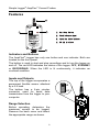
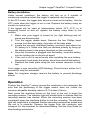
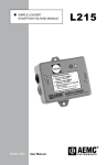
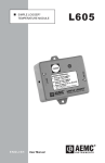
Simple Logger® AmpFlex® Current Probes AL24-2500 / AL36-2500 AL24-5000 / AL36-5000 USER MANUAL Statement of Compliance Chauvin Arnoux®, Inc. d.b.a. AEMC® Instruments certifies that this instrument has been calibrated using standards and instruments traceable to international standards. We guarantee that at the time of shipping your instrument has met its published specifications. An NIST traceable certificate may be requested at the time of purchase, or obtained by returning the instrument to our repair and calibration facility, for a nominal charge. The recommended calibration interval for this instrument is 12 months and begins on the date of receipt by the customer. For recalibration, please use our calibration services. Refer to our repair and calibration section at www.aemc.com. Serial #: Catalog #: 2113.72/2113.73/2113.74/2113.75 Model #: AL24-2500/AL36-2500/AL24-5000/AL36-5000 Please fill in the appropriate date as indicated: Date Received: Date Calibration Due: Chauvin Arnoux®, Inc. d.b.a AEMC® Instruments www.aemc.com Table of Contents Warning ................................................................................................... 3 International Electrical Symbols .............................................................. 3 Receiving Your Shipment........................................................................ 4 Packaging................................................................................................ 4 Specifications .......................................................................................... 4 Features .................................................................................................. 6 Indicators and Buttons ...................................................................... 6 Inputs and Outputs ........................................................................... 6 Range Selection ............................................................................... 6 Battery Installation ............................................................................ 7 Operation................................................................................................. 7 Software .................................................................................................. 8 Minimum Computer Requirements................................................... 8 Installation......................................................................................... 8 Using the Software ........................................................................... 9 Cleaning .................................................................................................. 9 Repair and Calibration .......................................................................... 10 Technical Assistance and Sales ........................................................... 10 Limited Warranty ................................................................................... 10 Warranty Repairs .................................................................................. 10 2 Simple Logger® AmpFlex® Current Probes Warning These safety warnings are provided to ensure the safety of personnel and proper operation of the instrument. • Read the instruction manual completely and follow all the safety information before attempting to use or service this instrument. • Use caution on any circuit: Potentially high voltages and currents may be present and may pose a shock hazard. • Read the specifications section prior to using the probes. Never exceed the maximum voltage ratings given. • Safety is the responsibility of the operator. • For maintenance, use only original replacement parts. • NEVER open the back of the instrument while connected to any circuit or input. • ALWAYS inspect the instrument and leads prior to use. Replace any defective parts immediately. • NEVER use the Simple Logger® AmpFlex® Current Probes on electrical conductors rated above 600V in overvoltage Category III (CAT III). International Electrical Symbols This symbol signifies that the loggers are protected by double or reinforced insulation. Use only specified replacement parts when servicing the instrument. This symbol signifies CAUTION! and requests that the user refer to the user manual before using the instrument. For more information about the Logger, refer to CD-ROM: USER GUIDE 3 Simple Logger® AmpFlex® Current Probes Receiving Your Shipment Upon receiving your shipment, make sure that the contents are consistent with the packing list. Notify your distributor of any missing items. If the equipment appears to be damaged, file a claim immediately with the carrier and notify your distributor at once, giving a detailed description of any damage. Packaging The AmpFlex® Current Probes include the following: • User manual • One 9V battery • CD-ROM containing the Windows® 2000, ME, NT and XP download and graphic software, a generic user guide, product specific manual and the Simple Logger® catalog. • 6 ft RS-232 cable Specifications ELECTRICAL Number of Channels: 1 Current Ranges: 2 Input: AL24/36-2500 - 250/2500 Arms (internally selectable) AL24/36-5000 - 500/5000 Arms (internally selectable) Input Connection: Permanent Flexible Sensor *Accuracy: <12.5% of Scale 1% of Reading + 2 x Resolution >12.5% of Scale 1% of Reading + Resolution Resolution: AL24/36-2500: 250 Arms AL24/36-2500: 2500 Arms Scale Range Maximum Input 100% 250 Arms 50% 125 Arms 25% 62.5 Arms 12.5% 31.25 Arms Resolution 1 Arms 0.5 Arms 0.25 Arms 0.125 Arms Scale Range 100% 50% 25% 12.5% AL24/36-5000: 500 Arms Scale Range Maximum Input 100% 500 Arms 50% 250 Arms 25% 125 Arms 12.5% 62.5 Arms Maximum Input 2500 Arms 1250 Arms 625 Arms 312.5 Arms Resolution 10 Arms 5 Arms 2.5 Arms 1.25 Arms AL24/36-5000: 5000 Arms Resolution 2 Arms 1 Arms 0.5 Arms 0.25 Arms Scale Range 100% 50% 25% 12.5% 4 Maximum Input 5000 Arms 2500 Arms 1250 Arms 625 Arms Resolution 20 Arms 10 Arms 5 Arms 2.5 Arms Simple Logger® AmpFlex® Current Probes Sample Rate: 4096/hr max. Data Storage: 8192 readings Data Storage Technique: (TXR™) Time Extension Recording™ Power: 9V Alkaline NEDA 1604, 6JF22, 6LR61 Battery Life Recording: 6 months continuous recording @ 25°C Output: RS-232 via 5-pin circular connector; 1200 Bps INDICATORS Operation Mode Indicator: One Red LED Single Blink: STANDBY mode Double Blink: RECORD mode No Blinks: OFF mode Continuously On: Overload condition CONTROLS Operation Mode: Push Button, Internal Range: Slide Switch ENVIRONMENTAL Operating Temperature: -4 to +158°F (-20 to +70°C) Storage Temperature: -4 to +174°F (-20 to +80°C) Relative Humidity: 5 to 95% non-condensing MECHANICAL Size: 2-1/2 x 1-9/16 x 4-1/2” (63.5 x 40.64 x 114.3mm) Maximum Conductor Size: 24" length: 8" Ø; 36" length: 12" Ø Case: Weatherproof NEMA4X, IP65 rated SAFETY Working Voltage: IEC 1010-1, 600V, CAT III ORDERING INFORMATION Simple Logger® AmpFlex® Model AL24-2500 .................... Cat. #2113.72 Simple Logger® AmpFlex® Model AL36-2500 .................... Cat. #2113.73 Simple Logger® AmpFlex® Model AL24-5000 .................... Cat. #2113.74 Simple Logger® AmpFlex® Model AL36-5000 .................... Cat. #2113.75 *Reference condition: 23C 3K, 20 to 75% RH, Frequency 45-3000Hz, No AC external magnetic field, DC magnetic field 40A/m, centered conductor, battery voltage 9V 10%. 5 Simple Logger® AmpFlex® Current Probes Features 600 V CAT III !" " 1 3 # (1) Start/Stop Button (2) Flexible Sensor Input 1. Press to Start Logging (Logging = Two Blinks) 2. Press to Stop Logging (3) Operation Mode Indicator (Stand-By = One Blink) 3. Press & Hold 5 sec. to Shut Off (Off = No Blinks) Warning: All Data will be Deleted! $%&' (( ® (4) RS-232 Interface 99 CHAUNCY STREET BOSTON MA 02111, USA (617) 451-0227 Fax (617) 423-2952 www.aemc.com MADE IN USA BATTERY: 9 V, NEDA 1604, 6LF22, 6LR61 4 Indicators and Buttons The AmpFlex® Logger has only one button and one indicator. Both are located on the front panel. The button is used to start and stop recordings and to turn the logger on and off. The red LED indicates the status of the logger; OFF, STANDBY or RECORDING. When the LED is lit continuously, it indicates an overload condition. Inputs and Outputs The top of the logger incorporates a permanent flexible sensor attached by a 5 ft lead. The bottom has a 5-pin circular connector used for serial data transmission from the logger to your computer. HI LO HI LO Range Selection Before operating, determine the maximum current to be logged. Remove the back cover and select the appropriate range as shown. 6 Simple Logger® AmpFlex® Current Probes Battery Installation Under normal conditions, the battery will last up to 6 months of continuous recording unless the logger is restarted very frequently. In the OFF mode, the logger puts almost no load on the battery. Use the OFF mode when the logger is not in use. Replace the battery every six months in normal use. If the logger will be used at temperatures below 32°F (0°C) or is frequently turned on and off, replace the battery every three to four months. 1. Make sure your logger is turned off (no light blinking) and all inputs are disconnected. 2. Turn the logger upside down. Remove the four Phillips head screws from the base plate, then take off the base plate. 3. Locate the two-wire (red/black) battery connector and attach the 9V battery to it. Make sure that you observe polarity by lining up the battery posts to the proper terminals on the connector. 4. Once the connector is plugged onto the battery, insert the battery into the holding clip on the circuit board. 5. If the unit is not in record mode after installing the new battery, disconnect it and press the button twice then reinstall the battery. 6. Reattach the base plate using the four screws removed in step two. Your logger is now recording (LED blinking). Press the test button for 5 seconds to stop the instrument. Note: For long-term storage, remove the battery to prevent discharge effects. Operation Position the AmpFlex® sensor around the conductor to be measured. Be sure that the positioning of the logger sensor does not violate the minimum allowable bending radius of 0.75 inches (19mm). Next, press the start/stop button on the front of the unit to begin the recording session. The indicator light will double blink to indicate that the recording session has started. When the recording session has been completed, press the start/stop button to end the recording. The indicator light will single blink to indicate that the recording session has ended and the unit is in stand-by. Remove the logger from the conductor and transport it to the computer for data downloading. See the User Guide for downloading instructions. 7 Simple Logger® AmpFlex® Current Probes SOFTWARE MINIMUM COMPUTER REQUIREMENTS Processor: 486 or higher RAM Storage: 8MB Hard Drive Space: 8MB for application, approx. 400K for each stored file Environment: Windows® 98, 2000, ME, NT and XP Port Access: (1) 9-pin serial port and (1) parallel port for printer support INSTALLATION Your Simple Logger® software is supplied on a CD-ROM. To install the program, perform the following steps: Auto Run Disabled: If Auto Run is disabled, insert the Simple Logger® CD into the CD-ROM drive, then select Run from the Start Menu. In the dialog box that appears, type: D:\setup, then click the OK button. NOTE: In this example, your CD-ROM drive is assumed to be drive letter D. If this is not the case, substitute the appropriate drive letter. Auto Run Enabled: If Auto Run is enabled, insert the Simple Logger® CD into the CD-ROM drive and follow the on-screen prompts to complete the setup. • Select Simple Logger 6.xx • Select Acrobat Reader to install Adobe Reader • Select Explore CD to view the User Guide, Simple Logger® Catalog or user specific manuals in PDF format. To view the documents included on the CD-ROM, you must have Acrobat Reader installed on your machine. If you do not have it installed, you can install it from the Simple Logger® Software CD-ROM. Installing Acrobat Reader: Select Run from the Start Menu. In the dialog box that appears, type: D:\Acrobat\setup, then click OK. NOTE: In this example, your CD-ROM drive is assumed to be drive letter D. If this is not the case, substitute the appropriate drive letter. 8 Simple Logger® AmpFlex® Current Probes USING THE SOFTWARE Launch the software and connect the RS-232 cable from your computer to the logger. Note: The first time the program is launched you will need to select a language. Select “Port” from the menu bar and select the Com port you will be using (see your computer manual). Once the software automatically detects the baud rate, the logger will communicate with the computer. (ID number of the logger and number of points recorded displayed). Depending on the selected range, “ALXX-2500” or “ALXX-250” will be displayed and automatically scale the graph accordingly. Cleaning The body of the logger should be cleaned with a cloth moistened with soapy water. Rinse with a cloth moistened with clean water. Do not use solvent. 9 Simple Logger® AmpFlex® Current Probes Repair and Calibration To ensure that your instrument meets factory specifications, we recommend that it be submitted to our factory Service Center at one-year intervals for recalibration, or as required by other standards or internal procedures. For instrument repair and calibration: Contact our Service Center for a Customer Service Authorization number (CSA#). This will ensure that when your instrument arrives, it will be tracked and processed promptly. Please write the CSA# on the outside of the shipping container. If the instrument is returned for calibration, we need to know if you want a standard calibration, or a calibration traceable to N.I.S.T. (includes calibration certificate plus recorded calibration data). Chauvin Arnoux®, Inc. • d.b.a. AEMC® Instruments 15 Faraday Drive • Dover, NH 03820 USA Tel: (800) 945-2362 (Ext. 360) • (603) 749-6434 (Ext. 360) Fax: (603) 742-2346 or (603) 749-6309 [email protected] • (or contact your authorized distributor) Costs for repair, standard calibration, and calibration traceable to N.I.S.T. are available. NOTE: All customers must obtain a CSA# before returning any instrument. Technical and Sales Assistance If you are experiencing any technical problems, or require any assistance with the proper operation or application of your instrument, please call or e-mail our support hotline: Phone: (800) 343-1391 • (508) 698-2115 • [email protected] • www.aemc.com NOTE: Do not ship instruments to our Foxborough, MA address. Limited Warranty The AmpFlex® Current Probes are warranted to the owner for a period of one year from the date of original purchase against defects in manufacture. This limited warranty is given by AEMC® Instruments, not by the distributor from whom it was purchased. This warranty is void if the unit has been tampered with, abused or if the defect is related to service not performed by AEMC® Instruments. For full and detailed warranty coverage, read the Warranty Coverage Information, attached to the Warranty Registration Card or is available at www.aemc.com. What AEMC® Instruments will do: If a malfunction occurs within the one-year period, you may return the instrument to us for repair, provided we have your warranty registration information on file or a proof of purchase. AEMC® Instruments will, at its option, repair or replace the faulty material. Warranty Repairs What you must do to return an Instrument for Warranty Repair: First, request a Customer Service Authorization Number (CSA#) from our Service Department, then return the instrument along with the signed CSA Form. Write the CSA# on the outside of the shipping container. Return the instrument to: Chauvin Arnoux®, Inc. d.b.a. AEMC® Instruments Service Department 15 Faraday Drive • Dover, NH 03820 USA Tel: (800) 945-2362 (Ext. 360) • (603) 749-6434 (Ext. 360) Fax: (603) 742-2346 or (603) 749-6309 [email protected] Caution: To protect yourself against in-transit loss, insure your returned material. NOTE: All customers must obtain a CSA# before returning any instrument. 10 Chauvin Arnoux®, Inc. d.b.a AEMC® Instruments 15 Faraday Drive • Dover, NH 03820 www.aemc.com 99-MAN 100208 v12 07/08