1
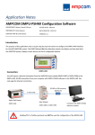
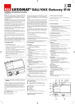
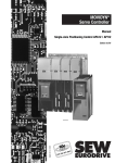
DMPU-PSHMI USER MANUAL rev. 0.1. 19 July 2012 DMPU-PSHMI User manual (19/07/2012) 1 Index 1 HARDWARE CHARACTERISTICS ................................................................................................................. 3 1.1 1.2 1.3 2 GENERAL NOTES ....................................................................................................................................... 5 2.1 2.2 2.3 2.4 3 CHARACTERISTICS ............................................................................................................................................. 3 DMPU-HMI WIRING DIAGRAMS ........................................................................................................................ 4 DIMENSIONS ................................................................................................................................................... 4 OPERATING SYSTEM ......................................................................................................................................... 5 SET UP MENU .................................................................................................................................................. 5 PC CONNECTION .............................................................................................................................................. 5 PASSWORD ..................................................................................................................................................... 6 PROJECT .................................................................................................................................................... 7 3.1 AT THE BEGINNING ........................................................................................................................................... 7 3.2 PROJECT OPTIONS............................................................................................................................................. 7 3.2.1 External Variables .............................................................................................................................. 8 3.3 MAIN INTERFACE............................................................................................................................................ 10 3.3.1 Display window ................................................................................................................................ 10 3.3.2 Alarms window ................................................................................................................................ 11 3.3.3 Buttons window ............................................................................................................................... 13 3.3.4 State bar .......................................................................................................................................... 13 3.3.5 Drop down menus ............................................................................................................................ 15 3.4 ADDING DISPLAY VARIABLES ............................................................................................................................. 17 4 IMAGES LIST .............................................................................................................................................19 DMPU-PSHMI User manual (19/07/2012) 2 Motor Controllers 1 HARDWARE CHARACTERISTICS HARDWARE CHARACTERISTICS 1.1 Characteristics Power supply 24VDC ±20% Current consumption < 300mA Operating temperature from -10 °C to +60 °C (R.H. <90% no condensation) Storage temperature from -10 °C to +70 °C (R.H. <90% no condensation) Installation category Cat. III (IEC60664, EN60664) EMC EN61000-6-2, EN61000-6-3 Standard compliance IEC60664, IEC61010-1, EN60664, EN61010-1 Weight approximately 195 g Keyboard 4 programmable function buttons Display Alphanumeric display backlit 2 x 8 characters Dimensions (WxHxD) 96 x 48 x 88.5 mm 2 serial ports (COM 0 and COM 2). Serial ports COM 0: RS485 serial port dedicated to communication between DMPUHMI and PC. It allows to download the application program created with DMPU-PSHMI into DMPU-HMI and the DMPU-HMI's operating system upgrade. COM 2: RS485 serial port dedicated to Modbus RTU communication between DMPU-HMI and DMPU main module. DMPU-PSHMI User manual (19/07/2012) 3 Motor Controllers HARDWARE CHARACTERISTICS 1.2 DMPU-HMI wiring diagrams Figure 1-1 Power supply Figure 1-2 Communication ports 1.3 Dimensions Figure 1-3 Front panel size Figure 1-4 Panel cut out Figure 1-5 Depth size DMPU-PSHMI User manual (19/07/2012) 4 Motor Controllers 2 GENERAL NOTES GENERAL NOTES Read the following guide to properly configure and use the DMPU-HMI interface and the DMPU-PSHMI programming software. The software is the development environment to create the configuration and download it into DMPU-HMI device; this configuration summarizes the pages, alarms messages, the variables from DMPU displayed on the operator interface and the 4 function buttons. This manual describes the hardware and software characteristics to use DMPU-HMI. 2.1 Operating System DMPU-HMI's software part consists of operating system and application program. The operating system manages all the resources of the microcontroller and makes it available to the application program created by the user. Install DMPU-PSHMI software (suggested installation directory “Programs\DMPU-PSHMI”) on the PC. When downloading a configuration, the PC software automatically checks the compatibility between DMPU-HMI operating system and the application program; if an out-dated system version is present on the operator interface, the PC software provides to update the device's operating system. 2.2 Set up menu If the application program isn’t present on DMPU-HMI, at switch-on the “Set Up” menu is automatically displayed (after showing for a few seconds the message “No Appli” to inform that the device isn’t configured). If an application program is present on DMPU-HMI, the initial page is displayed. Press the fourth button at the bottom while switching on to access at “Set Up” menu. The set up menu has the following items: Version: shows the operating system version. Language: selects the working language if the application provides the multilanguage mode. Parameters: modifies some DMPU-HMI parameters, as the user password to protect the application pages. Use the fourth button on the bottom to access at menu and the first button on the top to exit. The two buttons in the middle are the up and down arrows and allow pages scroll. 2.3 PC connection Use the COM0 port to connect the PC (see paragraph “DMPU-HMI wiring diagrams”). This communication port is two wires RS485, so a USB/RS485 converter may be necessary to allow the connection with the PC. In the “Option” software's menu, select the serial port to which DMPU-HMI is connected, like in the following figure: DMPU-PSHMI User manual (19/07/2012) 5 Motor Controllers GENERAL NOTES Figure 2-6 Select the PC's serial port in this menu When the device is connected, the operator is able to: Download the application program from PC to DMPU-HMI (described in chapter “PROJECT”). Download the operating system from PC to DMPU-HMI. 2.4 Password DMPU-HMI provides a user password to protect the application's pages so, when a protected page is requested, the user must enter the password. The default user password is 1234 but it is possible to change it in the “Set Up” menu (see “Set up menu” paragraph). DMPU-PSHMI User manual (19/07/2012) 6 Motor Controllers 3 PROJECT PROJECT The following chapter analyses step by step a new DMPU-HMI project creation. 3.1 At the beginning When opening DMPU-PSHMI programming software, select from the menu “File” the “New Project” item, or push the button on the state bar. Both options are displayed in the following image: Figure 3-7 Create a new project The “Project Options” window is shown; in this window it is possible to define the project name, select the first page displayed at switch-on and set external variables to read/write from DMPU main module. 3.2 Project options The “Project options” window is automatically opened when creating a new project; it’s possible to open again this window while programming through the main interface button on the upper state bar or the “Display” drop-down menu. These options are shown in the following image: Figure 3-8 Select "project options" from menu The “Project Options” looks as follows: DMPU-PSHMI User manual (19/07/2012) 7 Motor Controllers PROJECT Figure 3-9 Project options window The parameters in this window are: Project: project name (free user's choice). All. Scroll: automatic alarm scroll time expressed in seconds (when multiple alarms are active). If this time is zero, the alarm scroll will be manual (through two middle buttons, arrow buttons), otherwise the alarms are displayed cyclically with a time interval defined in this parameter. Var. Externals: to configure the external variables to read/write from/on DMPU main module. COM 0: communication parameters between DMPU-HMI and PC using serial port. In this case DMPU-HMI behaves like a slave device. COM 2: communication parameters between DMPU-HMI and DMPU main module. The parameters must be the same as in DMPU. 3.2.1 External Variables The external variables are read or written, from/to DMPU device. In the “Project Options” menu, “Var. Externals” it is possible to decide the used external variables (Figure 3-10). Clicking “Add Variable”, the “New External Variable” window is shown (Figure 3-11) to define a variable name (user's free choice). This name and a progressive ID number are added to the variables list on the left (Figure 3-12 and Figure 3-13) where all the variables to read/write from/to DMPU-HMI are summarized. It’s possible to show, modify and save the selected variable's parameters in the right box (Figure 3-14); the parameters are the following: COM: serial port connected to DMPU main module. Node Address: DMPU slave address from which read/write variables. It's possible to connect more than one DMPU main module to one DMPU-HMI; the node address allows to select from which DMPU module the operator interface reads the external variables. Address [DEC]: decimal register number to read on DMPU device: see the registers list on the DMPU communication protocol. Dimension: data format type of the read/written variable; see DMPU protocol. Select how to manage the variable: Nothing: the variable isn't read and isn't written. DMPU-PSHMI User manual (19/07/2012) 8 Motor Controllers PROJECT Read continue: DMPU-HMI reads cyclically the variable from the DMPU regardless of the displayed page, this variable is stored inside the DMPU-HMI. Write continue: DMPU-HMI writes cyclically the variable's value stored into DMPU-HMI on DMPU regardless of the displayed page. Reading page: DMPU-HMI reads the variable from DMPU only when the page with this variable is displayed. Figure 3-11 New external variable Figure 3-10 External variables settings Figure 3-12 External variable parameters #1 Figure 3-13 Variable's name in the external variable's list Figure 3-14 External variable parameters #2 DMPU-PSHMI User manual (19/07/2012) 9 Motor Controllers PROJECT 3.3 Main interface The main programming interface is divided into the following parts: Status bar: button list to access the main software's features. ”Display” window (green): preview of the pages displayed on the operator interface; it is possible to scroll the inserted pages and modify the page's text and/or the displayed variables. “Alarms” window (yellow): preview of the alarm pages which are displayed on the operator interface; it is possible to scroll the pages and modify the texts. These alarms are associated to the 32 virtual alarms present in DMPU. When one of these alarms trips, the relevant alarm page is displayed. If more than one alarm is simultaneously active it is possible to scroll the display with the two middle buttons or use the automatic scroll function in “Project Options” (see the paragraph “Project options”). “Buttons” window: set the buttons functions on the operator interface. The buttons functions are associated to the page which is shown in the actual green “Display” window. Change the actual page to associate the functions for each page. “Page Variables” window: the list of variables which are used in the current page. Figure 3-15 Main interface window 3.3.1 Display window In this form (Figure 3-16) the page content is defined. Insert a text or an external variables defined inside “Project options” in the green box (double-click to open the variable selection window; this window is described later). Use the button on the state bar (described in “State bar” chapter) to insert more than one text and variables and to scroll the pages (the current page number is shown on the top in the right side of the state bar, Figure 3-17). In the red circle area of Figure 3-17 the current page number and name is highlighted. DMPU-PSHMI User manual (19/07/2012) 10 Motor Controllers PROJECT Figure 3-16 Display window Figure 3-17 Select the current page The page name is assigned by default with the structure “page XX”, where “XX” is the page number; this name can be changed in “Display” menu - “Page Option”. Figure 3-18 Page option 3.3.2 Alarms window In this form it is possible insert the alarm messages associated to DMPU's virtual alarms. DMPU-HMI allows to show up to 32 alarm pages. For each alarm message a specific text can be shown on the operator interface when the alarm is active. DMPU-PSHMI User manual (19/07/2012) 11 Motor Controllers PROJECT Figure 3-19 Alarm window In the first row the tripped alarm number and the total number of the tripped alarms (“Alxx Tyy” where “xx” is the alarm number and “yy” is the total number of alarms) is shown. To customise a specific alarm window, select the alarm in the scroll list, like in following figure: Figure 3-20 Alarm selection Choose if the alarm message is shown or not when the alarm trips selecting or deselecting the flag on the “Show alarm” box (Figure 3-21): if the alarm message is disabled, the message isn't shown on the operator interface (although the associated DMPU's alarm trips). Figure 3-21 Enable/disable alarm display Define in the “Project option” menu how to display the alarm messages selecting or deselecting the flag on the “Immediate Alarms” box: if the box is enabled, the alarm message will be immediately shown on the operator interface when the alarm becomes active (replacing the current page); otherwise the alarm message is shown only after pressing the fourth button at the bottom of DMPU-HMI. The alarm condition is just shown by the red LED in this case. Figure 3-22 Enable/disable the immediate alarms display DMPU-PSHMI User manual (19/07/2012) 12 Motor Controllers PROJECT Use the two middle buttons (second and third one) on the operator interface to scroll among the active alarms. 3.3.3 Buttons window The buttons window, as the display window, refers to the page currently shown on the state bar (Figure 3-17); every page can have a different buttons setup. Figure 3-23 Buttons window Set the macros of the operator interface buttons double clicking on the button image in the buttons window to open the “Macro & Link” window. A macro is an operation done immediately by DMPU-HMI at the button pressure. The available macro are the following (one or two parameters can be required according to the macro type). MACRO Description Parameter 1 Parameter 2 MAC_NULL No operation / / MAC_PAGE Change page New page number / MAC_WRITE Write a value in DMPU-HMI variable. External variable address Value to write at this address MAC_TOGGLE Reversing a bit state Address Bit number [0...15] a For example use the macro “MAC_PAGE” to change the current page defining the destination page number. 3.3.4 State bar Use the upper state bar, in the main software interface, to manage the project. Figure 3-24 State bar DMPU-PSHMI User manual (19/07/2012) 13 Motor Controllers PROJECT In the following table the state bar functions are described: PAGE MANAGEMENT BUTTONS Button Description Insert a page in the current position. Add one page in the end without modifying the pages order. Delete the selected page. Go to the first project page/alarm. Go to the previous project page/alarm. Go to the last project page/alarm. Cut the selected element on display. Copy the selected element on display. Paste on display the element previously copied. Left aligned display text. Center aligned display text. Right aligned display text. Number (on the left) and name (on the right) of the current page. FILE MANAGEMENT BUTTONS Button Description Exit from the current project. FILE MANAGEMENT BUTTONS Button Description Create a new project. DMPU-PSHMI User manual (19/07/2012) 14 Motor Controllers PROJECT Open a new project. Save the current project. PROJECT BUTTONS Button Description Compile the current project. Compile and transmit the application from PC to DMPUC-HMI. DISPLAYING BUTTONS Button Description Show the buttons window. Show the alarms window. Show the variables window. Show the macros window. Show the project options window. Show the display window. 3.3.5 Drop down menus At the top of the software window there are some drop down menus. Figure 3-25 Drop down menus The drop down menus items are: File New project Create a new project. Open Project Open an existing project. Upload configuration file Open an example project Save Project Save the current project. DMPU-PSHMI User manual (19/07/2012) 15 Motor Controllers PROJECT File Save Project With Name Save the current project with a different name. Text Project Management Import/export the language strings in a “.csv” file. Project information Display the project info. Print Print a document which summarizes the project giving the opportunity to select what to print. Exit Exit from the current project. Options PC COM Port Select the PC serial port to use. PC Language Select the software language. Display Display Show/hide the display window. Buttons Show/hide the buttons window. Alarms Show/hide the alarms window. Page Variables Page Macro Go to Pag/Alr … First Previous Show/hide the page variables window. Show/hide the page macros window. Select the page to show. Go to the first project page. Go to the previous page. Next Go to the next page. Last Go to the last project page. Project Options Open the “Project Options” window. Alarm Option Open the “Page Option” window. Auto Update If this item is selected, the operating system on DMPU-HMI is automatically updated if it is different from the one on the PC. Connection Info If this item is selected, prompting messages are shown while downloading the configuration. Bar Link's Page Enable/disable the down bar where are indicated the buttons used for the page changing. Project Compile Send Application Compile + Send Appli. Auto Link Remove Link Compile the current project. Send the application from PC to DMPU-HMI. Compile the current project and send it to the DMPU-HMI. Use this function to set automatically the changing pages buttons for all the pages (all the pages use the same buttons to change page). Remove the change page links. DMPU-PSHMI User manual (19/07/2012) 16 Motor Controllers PROJECT Project Operation System Update Update the operating system on DMPU-HMI. Modify Cut Cut the selected object. Copy Copy the selected object. Paste Paste the selected object. Cut Page/Alarm Cut the current page. Copy Page/Alarm Copy the current page. Paste Page/Alarm Paste the current page. Insert Insert a page in the present position. Append Add one page in the end without modifying the present order. Delete Delete the current page. Append “x” Pag. Insert new Language Delete current Language Rename current Language Insert a block of new pages. Insert a new language. The current language is deleted. The current language is renamed. ? Help Show this manual. Info Software version. 3.4 Adding display variables After defining the external variables (see paragraph “Project options”) it is possible to insert them on the display double-clicking the display window. In this way the “Variable set up” window is shown: DMPU-PSHMI User manual (19/07/2012) 17 Motor Controllers PROJECT Figure 3-26 variable set up window In this window the features of the displayed variables are defined: Min. (DEC): minimum variable value (if it is lower than minimum, underscores characters instead of digits are displayed). Max. (DEC): maximum variable value (if it is higher than maximum, high scores characters instead of digits are displayed). Digits: number of integers digits used to display the variable. Dec. Digits: number of decimal digits used to display the variable. ENG: displays the variable in engineering units with their conversion factors. This is the line equation. Use this function to re-scale a variable Figure 3-27 Function to re-scale a variable RFS: the displayed variable is continuously updated (if this function is disabled, the variable is updated only when opening the page). DMPU-PSHMI User manual (19/07/2012) 18 Motor Controllers 4 Images list Images list Figure 1-1 Power supply............................................................................................................... 4 Figure 1-2 Communication ports.................................................................................................. 4 Figure 1-3 Front panel size ........................................................................................................... 4 Figure 1-4 Panel cut out ............................................................................................................... 4 Figure 1-5 Depth size ................................................................................................................... 4 Figure 2-6 Select the PC's serial port in this menu ....................................................................... 6 Figure 3-7 Create a new project ................................................................................................... 7 Figure 3-8 Select "project options" from menu ............................................................................ 7 Figure 3-9 Project options window .............................................................................................. 8 Figure 3-10 External variables settings ........................................................................................ 9 Figure 3-11 New external variable ............................................................................................... 9 Figure 3-12 External variable parameters #1 ............................................................................... 9 Figure 3-13 Variable's name in the external variable's list ........................................................... 9 Figure 3-14 External variable parameters #2 ............................................................................... 9 Figure 3-15 Main interface window ........................................................................................... 10 Figure 3-16 Display window ...................................................................................................... 11 Figure 3-17 Select the current page ............................................................................................ 11 Figure 3-18 Page option ............................................................................................................. 11 Figure 3-19 Alarm window ........................................................................................................ 12 Figure 3-20 Alarm selection ....................................................................................................... 12 Figure 3-21 Enable/disable alarm display .................................................................................. 12 Figure 3-22 Enable/disable the immediate alarms display ......................................................... 12 Figure 3-23 Buttons window ...................................................................................................... 13 Figure 3-24 State bar .................................................................................................................. 13 Figure 3-25 Drop down menus ................................................................................................... 15 Figure 3-26 variable set up window ........................................................................................... 18 Figure 3-27 Function to re-scale a variable ................................................................................ 18 DMPU-PSHMI User manual (19/07/2012) 19