1
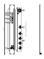
Kramer Electronics, Ltd.
USER MANUAL
Model:
VS-41DVI-R
4x1 DVI Switcher
Contents
Contents
1
2
3
4
4.1
Introduction
Getting Started
Overview
Using a VS-41DVI-R 4x1 DVI Switcher
Using the VS-41DVI-R EDID Button
1
1
2
4
5
4.1.1
4.1.2
Changing the EDID
Restoring the Default EDID
6
6
5
Technical Specifications
6
Figures
Figure 1: VS-41DVI-R 4x1 DVI Switcher
Figure 2: Connecting a VS-41DVI-R 4x1 DVI Switcher
3
5
Tables
Table 1: VS-41DVI-R 4x1 DVI Switcher Front Panel Features
Table 2: VS-41DVI-R 4x1 DVI Switcher Rear Panel Features
Table 3: Technical Specifications of the VS-41DVI-R
4
4
6
i
Introduction
1
Introduction
Welcome to Kramer Electronics (since 1981): a world of unique, creative and
affordable solutions to the infinite range of problems that confront the video,
audio and presentation professional on a daily basis. In recent years, we have
redesigned and upgraded most of our line, making the best even better! Our
350-plus different models now appear in 8 Groups1, which are clearly defined
by function.
Congratulations on purchasing your Kramer VS-41DVI-R 4x1 DVI
Switcher2.
The VS-41DVI-R is ideal for conference room presentations and advertising
applications, as well as for rental and staging. Each package includes the
following items:
VS-41DVI-R 4x1 DVI Switcher
Power cord
This user manual3
2
Getting Started
We recommend that you:
Unpack the equipment carefully and save the original box and packaging
materials for possible future shipment
Review the contents of this user manual
Use Kramer high performance high resolution DVI cables4
1 GROUP 1: Distribution Amplifiers; GROUP 2: Video and Audio Switchers, Matrix Switchers and Controllers; GROUP 3:
Video, Audio, VGA/XGA Processors; GROUP 4: Interfaces and Sync Processors; GROUP 5: Twisted Pair Interfaces;
GROUP 6: Accessories and Rack Adapters; GROUP 7: Scan Converters and Scalers; and GROUP 8: Cables and Connectors
2 VS-41DVI instead of VS-41DVI-R may be printed on some versions of this machine
3 Download up-to-date Kramer user manuals from our Web site at http://www.kramerelectronics.com
4 The complete list of Kramer cables is on our Web site at http://www.kramerelectronics.com
1
Overview
3
Overview
The VS-41DVI-R is a technologically advanced, high quality 4x1 Switcher
for DVI-D signals supporting the DDWG DVI 1.0 standard.
With a bandwidth of 1.65GHz, the VS-41DVI-R can switch signals having
resolutions up to UXGA, including all HDTV formats. Since high-resolution
DVI signals are very sensitive to cable quality and to PCB layout, the
VS-41DVI-R uses a carefully designed PCB, which includes all buffering,
conditioning and amplifying circuitry to provide a re-clocked
top-notch output signal.
In addition the VS-41DVI-R:
Includes a built-in reclocking block that re-generates the DVI signal, so
that several units may be cascaded
Can read and store, in non-volatile memory, the EDID1 block of the
display device. It can then provide the EDID information to all of the DVI
sources even if the display device is not connected
Does not support HDCP (High Definition Digital Content Protection)
Has five DVI-I connectors to make it compatible with all types of DVI
cables
Fits in one vertical space of a standard 19” professional rack enclosure
Achieving the best performance means:
Connecting only good quality connection cables, thus avoiding
interference, deterioration in signal quality due to poor matching, and
elevated noise levels (often associated with low quality cables)
Avoiding interference from neighboring electrical appliances and positioning
your VS-41DVI-R away from moisture, excessive sunlight and dust
Figure 1 illustrates the front and rear panels of the VS-41DVI-R. Table 1 and
Table 2 define the front and rear panels of the VS-41DVI-R, respectively.
1 EDID is Extended Display Identification Data
2
KRAMER: SIMPLE CREATIVE TECHNOLOGY
Figure 1: VS-41DVI-R 4x1 DVI Switcher
Overview
3
Using a VS-41DVI-R 4x1 DVI Switcher
Table 1: VS-41DVI-R 4x1 DVI Switcher Front Panel Features
#
1
2
3
4
5
Feature
POWER Switch
MUTE Button
INPUT SELECTOR Buttons
EDID Button
PANEL LOCK Button
Function
Illuminated switch for turning the unit ON or OFF
Press to turn output off
Press the INPUT button (1 to 4) to select input
Press the EDID button to acquire EDID information from display
Press to disengage front panel buttons
Table 2: VS-41DVI-R 4x1 DVI Switcher Rear Panel Features
Function
Connect to the DVI sources
Connect to the DVI acceptor
AC connector enabling power supply to the unit
6
7
8
Feature
INPUT 1 through INPUT 4 DVI Connectors
OUTPUT DVI Connector
Power Connector with Fuse
4
Using a VS-41DVI-R 4x1 DVI Switcher
#
To use the VS-41DVI-R 4x1 DVI Switcher (as in Figure 2), do the
following1:
1. Connect up to 4 DVI sources to the INPUT connectors, as follows:
INPUT 1 connector to DVI source 1 (for example, a computer)
INPUT 2 connector to DVI source 2 (for example, a computer)
INPUT 3 connector to DVI source 3 (for example, a computer)
INPUT 4 connector to DVI source 4 (for example, a computer)
2. Connect the OUTPUT connector to the DVI acceptor (for example, a
monitor).
3. Connect the power connector to the mains electricity.
4. Turn ON the power.
5. Press an INPUT SELECTOR button (1 to 4) to choose which DVI input
to route to the output2.
6. Press the EDID button to acquire the EDID information (see section
4.1).
7. Press the PANEL LOCK button if you want to disengage the front panel
buttons.
1 Switch OFF the power on each device before connecting it to your VS-41DVI-R. After connecting your VS-41DVI-R,
switch on its power and then switch on the power on each device
2 If the input is connected and active, the respective input button illuminates. If a source is not connected, the input button
flashes
4
KRAMER: SIMPLE CREATIVE TECHNOLOGY
Using a VS-41DVI-R 4x1 DVI Switcher
Computer
Graphics Source 1
Computer
Graphics Source 4
Display
Figure 2: Connecting a VS-41DVI-R 4x1 DVI Switcher
4.1 Using the VS-41DVI-R EDID Button
The EDID button enables you to acquire the output EDID information.
When powering the VS-41DVI-R, the EDID button flashes if the machine
detects an EDID different to the one stored in the machine’s non-volatile
memory. Otherwise the EDID button does not flash and is not illuminated.
5
Technical Specifications
4.1.1
Changing the EDID
To acquire the EDID of a new output display:
1. Connect the new output display.
2. Turn ON the power.
The EDID button flashes.
3. Press the EDID button.
The EDID button is illuminated while the VS-41DVI-R reads the EDID.
The EDID is stored in the non-volatile memory when the EDID button
no longer illuminates.
4.1.2
Restoring the Default EDID
To restore the default EDID, do the following:
1. Disconnect the output.
2. Turn OFF the power.
3. Turn ON the Power.
The EDID button flashes.
4. Press the EDID button.
The EDID button illuminates.
The default EDID is stored in the non-volatile memory when the EDID
button no longer illuminates.
5
Technical Specifications
Table 3 includes the technical specifications:
1
Table 3: Technical Specifications of the VS-41DVI-R
INPUTS:
OUTPUT:
BANDWIDTH (-3dB):
POWER SOURCE:
DIMENSIONS:
WEIGHT:
ACCESSORIES:
2
4 DVI , 1.2Vpp on a DVI Molex 24pin female connector; DDC signal 5Vpp (TTL)
1 DVI2, 1.2Vpp on DVI Molex 24pin female connectors; DDC signal 5Vpp (TTL)
1.65GHz
100 264VAC; 50/60Hz
19-inch (W), 7-inch (D), 1U (H)
2.5 kg. (5.5 lbs.) approx.
Power Cord
1 Specifications are subject to change without notice
2 On a DVI-I connector. Note that only the digital signal (DVI-D) is available on the DVI connector
6
KRAMER: SIMPLE CREATIVE TECHNOLOGY
LIMITED WARRANTY
Kramer Electronics (hereafter Kramer) warrants this product free from defects in material and workmanship under the
following terms.
HOW LONG IS THE WARRANTY
Labor and parts are warranted for three years from the date of the first customer purchase.
WHO IS PROTECTED?
Only the first purchase customer may enforce this warranty.
WHAT IS COVERED AND WHAT IS NOT COVERED
Except as below, this warranty covers all defects in material or workmanship in this product. The following are not covered
by the warranty:
1.
2.
3.
Any product which is not distributed by Kramer, or which is not purchased from an authorized Kramer dealer. If you are
uncertain as to whether a dealer is authorized, please contact Kramer at one of the agents listed in the Web site
www.kramerelectronics.com.
Any product, on which the serial number has been defaced, modified or removed.
Damage, deterioration or malfunction resulting from:
i)
Accident, misuse, abuse, neglect, fire, water, lightning or other acts of nature
ii)
Product modification, or failure to follow instructions supplied with the product
iii)
Repair or attempted repair by anyone not authorized by Kramer
iv)
Any shipment of the product (claims must be presented to the carrier)
v)
Removal or installation of the product
vi)
Any other cause, which does not relate to a product defect
vii)
Cartons, equipment enclosures, cables or accessories used in conjunction with the product
WHAT WE WILL PAY FOR AND WHAT WE WILL NOT PAY FOR
We will pay labor and material expenses for covered items. We will not pay for the following:
1.
2.
3.
Removal or installations charges.
Costs of initial technical adjustments (set-up), including adjustment of user controls or programming. These costs are the
responsibility of the Kramer dealer from whom the product was purchased.
Shipping charges.
HOW YOU CAN GET WARRANTY SERVICE
1.
2.
3.
To obtain service on you product, you must take or ship it prepaid to any authorized Kramer service center.
Whenever warranty service is required, the original dated invoice (or a copy) must be presented as proof of warranty coverage,
and should be included in any shipment of the product. Please also include in any mailing a contact name, company, address, and
a description of the problem(s).
For the name of the nearest Kramer authorized service center, consult your authorized dealer.
LIMITATION OF IMPLIED WARRANTIES
All implied warranties, including warranties of merchantability and fitness for a particular purpose, are limited in duration to
the length of this warranty.
EXCLUSION OF DAMAGES
The liability of Kramer for any effective products is limited to the repair or replacement of the product at our option. Kramer
shall not be liable for:
1.
2.
Damage to other property caused by defects in this product, damages based upon inconvenience, loss of use of the product, loss
of time, commercial loss; or:
Any other damages, whether incidental, consequential or otherwise. Some countries may not allow limitations on how long an
implied warranty lasts and/or do not allow the exclusion or limitation of incidental or consequential damages, so the above
limitations and exclusions may not apply to you.
This warranty gives you specific legal rights, and you may also have other rights, which vary from place to place.
NOTE: All products returned to Kramer for service must have prior approval. This may be obtained from your dealer.
This equipment has been tested to determine compliance with the requirements of:
EN-50081:
"Electromagnetic compatibility (EMC);
generic emission standard.
Part 1: Residential, commercial and light industry"
EN-50082:
"Electromagnetic compatibility (EMC) generic immunity standard.
Part 1: Residential, commercial and light industry environment".
CFR-47:
FCC Rules and Regulations:
Part 15: “Radio frequency devices
Subpart B – Unintentional radiators”
CAUTION!
Servicing the machines can only be done by an authorized Kramer technician. Any user who makes changes or modifications to
the unit without the expressed approval of the manufacturer will void user authority to operate the equipment.
Use the supplied DC power supply to feed power to the machine.
Please use recommended interconnection cables to connect the machine to other components.
7
For the latest information on our products and a list of Kramer
distributors, visit our Web site: www.kramerelectronics.com,
where updates to this user manual may be found.
We welcome your questions, comments and feedback.
Kramer Electronics, Ltd.
Web site: www.kramerelectronics.com
E-mail: [email protected]
P/N: 2900-000029 REV 1