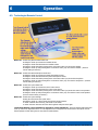
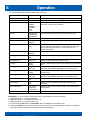
1
Installation / Operation Manual VisuaStim Digital Resonance Technology, Inc. 18121 Parthenia Street Northridge, California 91325, USA +1 (818) 882-1997 +1 (800) 428-MRTV www.mrivideo.com Innovative MRI-Compatible Virtual Entertainment System for Advanced Functional MRI Resonance Technology, Inc. VisuaStim System Installation / Operation Manual: RTC-VS Rev 11 Notice: This document contains proprietary information protected by copyright. All rights reserved. No part of the document may be photocopied or reproduced without the prior written consent of Resonance Technology, Inc. Information contained in this document is covered by one or more of the following U.S. patents: 5627902, 5877732, 5432544, 5412419. Resonance Technology, Inc. VisuaStim System Installation / Operation Manual: RTC-VS Rev 11 Table of Contents 1. Introduction .......................................................................................... 1 2. Safety Information ................................................................................ 2 2.1. Important Warnings for Patient and Operator Safety ................................................................ 2 2.2. Precautionary Patient Conditions ................................................................................................ 2 2.3. Use Restrictions ........................................................................................................................... 3 2.4. MRI Environment Hazards........................................................................................................... 3 2.5. General Warnings for Electronic Products .................................................................................. 4 2.6. Labeling Used to Indicate Device Safety ..................................................................................... 4 2.7. Medical Device Safety Approvals ................................................................................................. 5 3. Installation Materials ............................................................................ 6 3.1. Control Room Components.......................................................................................................... 6 3.2 Magnet Room Components ......................................................................................................... 6 3.3 Equipment Room Components .................................................................................................... 7 3.4 Installation Items ........................................................................................................................ 7 3.5 Accessories .................................................................................................................................. 7 4. Room Layout Overview for Installation ................................................ 8 5. Installation Procedure ........................................................................... 9 5.1. Installing the MR Laser Link Cable and Transducer Power Supply Cables ............................... 10 5.2. Magnet Room Component Interconnection .............................................................................. 11 5.3. Equipment Room Component Interconnection ......................................................................... 12 5.4. Control Room Component Interconnection .............................................................................. 13 5.5. PC Setup/Configuration for Video Compatibility ...................................................................... 15 6. Operation ............................................................................................. 16 6.1. VisuaStim System Features ....................................................................................................... 16 6.2. Front Panel Controls and Indicators ......................................................................................... 17 6.2.1. 6.2.2. Buttons ................................................................................................................................... 17 Indicators ............................................................................................................................... 17 6.3. Technologist Remote Control .................................................................................................... 19 6.4. Performing Data Integrity Tests on the Magnet ....................................................................... 21 6.5. Patient Setup ............................................................................................................................. 21 6.5.1. 6.5.2. 6.5.3. Overview ................................................................................................................................. 21 Audio Setup ............................................................................................................................ 21 Video Setup............................................................................................................................. 22 Resonance Technology, Inc. VisuaStim System Installation / Operation Manual: RTC-VS Rev 11 Table of Contents 6.5.4. Displaying 3D Video on the Goggles ...................................................................................... 22 6.6. MR Trigger Synchronization Setup............................................................................................ 24 6.7. Cleaning..................................................................................................................................... 27 7. Specifications ...................................................................................... 28 7.1. VisuaStim Controller ................................................................................................................. 28 7.1.1. 7.1.2. 7.1.3. 7.1.4. 7.2. Remote Interface / Patient Intercom Speaker ......................................................................... 28 7.2.1. 7.3. Physical Characteristics ......................................................................................................... 29 Electrical Characteristics ........................................................................................................ 29 Video Goggle ............................................................................................................................. 29 7.5.1. 7.5.2. 7.6. Physical Characteristics ......................................................................................................... 28 VisuaStim Transducer ............................................................................................................... 29 7.4.1. 7.4.2. 7.5. Physical Characteristics ......................................................................................................... 28 Technologist Remote Control .................................................................................................... 28 7.3.1. 7.4. Physical Characteristics ......................................................................................................... 28 Power Input ............................................................................................................................ 28 A/V Interfaces ........................................................................................................................ 28 Trigger Interfaces .................................................................................................................. 28 Physical Characteristics ......................................................................................................... 29 Display Characteristics ........................................................................................................... 29 Audio Headset ........................................................................................................................... 29 7.6.1. Acoustical Characteristics ...................................................................................................... 29 8. Support Information ............................................................................ 30 Resonance Technology, Inc. VisuaStim System Installation / Operation Manual: RTC-VS Rev 11 Resonance Technology, Inc. VisuaStim System Installation / Operation Manual: RTC-VS Rev 11 1 Introduction 1. Introduction Congratulations on your purchase of the VisuaStim Digital MRI-compatible fMRI system with high resolution stereo 3D glasses. This device represents more than 40 years of development and state-of-the-art engineering. We are confident this product will give you the tools you need for sophisticated fMRI visual/audio stimulation research presentations. This installation/operation manual outlines how to properly install and operate the system. Thank you for choosing to purchase this advanced fMRI system from Resonance Technology, Inc., the leader in fMRI and MRI patient comfort systems. Suggestions on how to improve this system are always welcome. Sincerely, Mokhtar Ziarati President and CEO Resonance Technology, Inc. - Page 1 Resonance Technology, Inc. VisuaStim System Installation / Operation Manual: RTC-VS Rev 11 2 Safety Information 2. Safety Information At Resonance Technology, Inc., patient safety is our top priority. Please review this section completely as its contents are vital to the safety of the installer, the clinician/operator, and the patient. 2.1. Important Warnings for Patient and Operator Safety WARNING Prior to every use, inspect all system components that come in contact with the patient. Discontinue product usage immediately if any damage is evident or presents other potential hazards. Use of damaged components may cause injury to the clinician or the patient. Examples of hazardous damage include but is not limited to the following: Protective lenses missing from the video goggles Cracked housing on video goggles or audio headset Microphone boom separated from headset housing (exposing wires) Cable padding torn, exposing cable inside Any damage potentially exposing wires to the patient 2.2. Precautionary Patient Conditions Eye Disease / Eye Injury / Glaucoma If the patient has been diagnosed with or is susceptible to eye disease, eye injuries, or glaucoma, instruct the patient to consult their doctor before using the video goggles. Use of this product by individuals with conditions such as glaucoma is not recommended. Heart Disease / High Blood Pressure If the patient has a history of heart disease or high blood pressure, instruct the patient to consult their doctor before using this system. If during viewing any increased anxiety is experienced, stop using this product immediately and instruct the patient to rest. If the symptoms persist after resting, instruct the patient to consult their doctor before continuing using this product. Seizures If the patient has a history of temporary spasms, unconsciousness, or epileptic seizures from light stimulation, instruct the patient to consult their doctor before using this system. Use of this product by such individuals may cause spasms, unconsciousness, or seizures. If the patient experiences such symptoms, stop using the product immediately and instruct the patient to consult their doctor. Sickness / Headache / Nausea If during use, the patient experiences any of the following symptoms, stop using this product immediately and rest. These symptoms may indicate misuse or overuse of the product or that you should not use the product for health reasons. If the following symptoms persist after rest, consult your doctor. Sore eyes, eye fatigue, or double vision Headache Inability to focus on the screen Stiff or sore shoulders or neck For patient safety, the patient video goggles turn off automatically after six hours of continuous use. Read this user manual for instructions on how to reset the video goggles to continue viewing video images. Motion Sickness from using the Video Goggles Some patients may experience motion sickness, headache, or nausea from viewing visual paradigms or video programs, especially those with intense action and movement. If the patient experiences any of these symptoms, stop using the product immediately. To avoid personal injury or injury to others, do not operate a motor vehicle nor do anything that requires concentration until these symptoms disappear. - Page 2 Resonance Technology, Inc. VisuaStim System Installation / Operation Manual: RTC-VS Rev 11 2 Safety Information Loud Sound Volume Avoid using audio headset with high volume for the patient as hearing expert’s advice against continuous loud and extended audio play. If the patient experiences a ringing in their ears, reduce the audio headset volume. The patient is advised to consult their health doctor for further advice. 2.3. Use Restrictions Shelf-Life and System Maintenance Service Schedule The CinemaVision System comes with a one year original manufacturer warranty and a shelf life of two years from the date of installation. Optional extended warranty may be purchased for this system. With patient safety in mind, Resonance Technology, Inc. recommends periodic maintenance service for this CinemaVision System every six months after the one year original warranty period. Restrictions on Using Non-Resonance Technology, Inc. Components with the VisuaStim system The original manufacturer’s warranty will be voided if any non-Resonance Technology, Inc. Power Supply is used to provide power the VisuaStim Transducer. The original manufacturer’s warranty will be voided if other non-Resonance Technology, Inc. approved components are connected to the VisuaStim system. In addition, Resonance Technology, Inc. cannot be held responsible or liable for any unauthorized use of this equipment. If you have any questions about how to operate this system, please read this user manual or call Resonance Technology, Inc. customer service at (818) 882-1997 or email [email protected]. 2.4. MRI Environment Hazards Installation of materials inside the MRI suite must be done with extreme caution and only by authorized personnel. Care must be taken to keep ferromagnetic materials such as tools, filter plates, screws, etc. at least three meters (approximately 10 feet) away from the energized magnet. Absolutely no work should be done near the filter panel when a scan is in progress. All cabling inside the MRI environment should either be connected or terminated properly. Failure to do so may result in skin burns related to RF energy. All cables should be run straight and never looped, as this may also cause serious skin burns inside the MRI room. In addition, no persons with ferromagnetic prosthetic devices such as pacemakers or joint replacements should enter the MRI suite at any time. Extremely high magnetic forces have the potential to dislodge ferrous items at high velocities that can result in serious injury or death. Only system components explicitly designated for use in the MRI suite should be placed inside the MRI suite. Components not designated for use inside the MRI suite may present a projectile hazard and can become airborne, causing property damage, serious bodily injury, or death. Please refer to the installation block diagram to determine which components belong inside the MRI suite. Resonance Technology, Inc. will not be held liable for any injuries or property damage which may occur as the result of improper use or installation of this product. By agreeing to this notice, users certify that they are familiar with basic safety procedures in an MRI room environment and that they have read and understand these safety precautions. For questions regarding installation procedures or this manual, Resonance Technology, Inc. technical support staff may be reached Monday through Friday 8 a.m. to 5 p.m., Pacific Standard Time at (818) 882-1997, or by email at [email protected]. - Page 3 Resonance Technology, Inc. VisuaStim System Installation / Operation Manual: RTC-VS Rev 11 2 Safety Information 2.5. General Warnings for Electronic Products Electric shock Failure to observe all operating and maintenance instructions may cause damage to this product and may result in property damage and/or injury or death from electric shock, fire, or other cause. Do not disassemble this product. Only Resonance Technology, Inc. trained and authorized personnel should perform all required service for this product. Failure to comply with this warning may result in property damage, injury and/or death from electric shock, fire, or other cause. Avoid exposing this product to extreme environments. This product may be damaged by high temperatures, direct sunlight exposure, by dropping this product, or by other mechanical shock. Do not expose this product to rain or excessive moisture. Avoid these conditions as the video goggle lenses may become damaged and may result in eye fatigue to the patient. Unplug this product when not in use for long periods of time. Always unplug this product when not in use for extended periods of time or during MRI maintenance. Leave connected if used daily. In addition, to prolong the life of the video goggle, use the Technologist Remote to turn off the power to the video goggle at night or when not in use. Note that if the system is not used for 2 hours, it will hibernate and you may have to press the Tech Remote TALK button to wake up the system. 2.6. Labeling Used to Indicate Device Safety Type BF Applied Part Devices that have conductive contact with the patient or have applied parts that are fixed in medium or long term contact with the patient. MR-Safe Device Device considered safe for use anywhere inside the magnet room. MR Conditionally-Safe Device Device considered safe in the MR room under certain conditions. MR Unsafe Device Device considered unsafe for use in the MR room. These items should not be taken inside the MR room due to being a projectile hazard in the magnetic field. - Page 4 Resonance Technology, Inc. VisuaStim System Installation / Operation Manual: RTC-VS Rev 11 2 Safety Information 2.7. Medical Device Safety Approvals The VisuaStim System has the following safety certifications: - Page 5 Resonance Technology, Inc. VisuaStim System Installation / Operation Manual: RTC-VS Rev 11 3 Installation Materials 3. Installation Materials Your VisuaStim system comes complete with all the necessary components to complete the system installation at your facility. The following checklists are provided for materials verification purposes. 3.1. Control Room Components Part Number Quantity Description RTC-330-170-000-101 1 VisuaStim Controller Unit RTC-330-170-093-000 1 VisuaStim Controller Rear Bracket RTC-650-040-000-000 1 Speaker System RTC-330-240-001-000 1 Remote Interface Speaker (for Control Room monitoring of patient) RTC-650-020-000-000 1 Technologist Remote Control RTC-VS 1 Installation / Operation Manual (This manual) RTC-LPS 1 Linear Power Supply Installation / Operation Manual (optional) RTC-101-525-001-000 1 HD-15 Female-to-Female Cable, 3’ PCM-2230-06B 2 HD-15 Male-to-Male VGA Cable, 6’ RTC-330-170-404-000 2 1/8” Mini-Stereo Cable, 6’ RTC-101-306-003-000 2 Hospital Grade AC Power Cord 129712-00 1 Cable bundling tubing (1 for Controller, 1 for Transducer Power Supply) 3.2 Magnet Room Components Part Number Quantity RTC-330-050-000-000 RTC-650-050-182-000 RTC-650-050-270-001 RTC-650-060-000-000 RTC-650-065-000-000 RTC-651-060-621-000 RTC-650-065-621-000 1 1 1 1 Description VisuaStim Transducer Transducer Mounting Plate (specific to your magnet type) Acrylic Transducer Stand (optional) Audio Headset w/ Microphone (soft-shell version) Audio Headset w/ Microphone (slim version) Headband for Soft-Shell Headset Headband for Slim Headset RTC-331-070-124-000 1 Video Goggle RTC-651-070-089-000 1 Goggle Mask RTC-650-070-458-000 1 Goggle Strap RTC-650-070-060-000 1 Set of Corrective Lenses, optional (Offered Upon Request) RTC-ALS-HDH 2 Headset Hooks RTC-651-000-453-000 1 Custom Headrest (for G.E. 8-channel coil) to fit audio headset RTC-101-245-001-001 1 Transducer DC Power cable – 15 meters (~50’) - Page 6 Resonance Technology, Inc. VisuaStim System Installation / Operation Manual: RTC-VS Rev 11 3 Installation Materials 3.3 Equipment Room Components Part Number Quantity Description RTC-650-300-000-001 1 Transducer MRI Medical Power Supply RTC-101-306-003-000 2 Hospital Grade AC Power Cord RTC-650-080-610-000 Filter Plate for G.E. Penetration Panel RTC-PL-502RB 1 RTC-ALS-FPP RTC-650-080-525-000 Filter Plate for Philips Penetration Panel Filter Plate for Siemens Penetration Panel (large version) Filter Plate for Siemens Penetration Panel (small version) RTC-650-300-605-000 1 9-pin D-Sub Filter RTC-101-210-001-001 1 Transducer DC Power cable – 3 meters (~10’) 3.4 Installation Items Part Number Quantity Description RTC-ALS-TWR 20 Tie Wraps RTC-ALS-TWH 20 Tie Wrap Holders RTC-101-112-001-000 1 12-Channel LC-type MR Laser Link Cable 3.5 Accessories Part Number Quantity Description RTC-ALS-HEC 50 Headset Earpiece Covers RTC-650-060-052-000 10 Headset Microphone Cushions - Page 7 Resonance Technology, Inc. VisuaStim System Installation / Operation Manual: RTC-VS Rev 11 4 Room Layout Overview for Installation 4. Room Layout Overview for Installation WARNING: Absolutely no ferromagnetic tools should be brought inside the MRI Suite! While no tools, other than tie wraps, are required to install the system in the MRI suite, absolutely all ferromagnetic tools remain outside of, and away from the door leading to, the MRI suite. Below is a typical MRI setup. Your individual installation may vary somewhat, but it will generally be spaced into three areas: Control Room, Computer/Equipment Room and MRI Suite or Magnet Room. The Control Room setup consists of placement and connection of the VisuaStim Controller, Technologist Remote Control, and stimulus computer with video monitor (not included). A 12-channel MR Laserlink fiber optic cable bundle is routed from the VisuaStim Controller in the Control Room through the filter panel waveguide in the Equipment room to the VisuaStim Transducer inside the Magnet Room. Inside the Magnet Room, the patient is fitted with the VisuaStim audio headset and video goggles. For power source, the VisuaStim Transducer utilizes a standalone power supply that must be installed outside the Magnet Room since it contains ferromagnetic components and has internal frequencies which may cause interference. This supply must be located outside the 20-Gauss line. The power delivered by this power supply is conducted via a power cable that is filtered at the penetration panel using low-pass DB-9 filters, depending on the type of magnet. Optionally, a Linear Medical Power Supply can be securely installed inside the Magnet Room outside the 200-Gauss line. With the exception of the audio headset and visor goggles, all the Magnet Room components of the VisuaStim must be installed to the side of the magnet shroud and never in line with the bore. Additionally, these components should be placed in an area not heavily trafficked to keep them from being damaged. - Page 8 Resonance Technology, Inc. VisuaStim System Installation / Operation Manual: RTC-VS Rev 11 5 Installation Procedure 5. Installation Procedure The installation procedure consists of four major phases: Installing the MR Laser Link Cable and Transducer Power Supply Cables Magnet Room Component Interconnection Equipment Room Component Interconnection Control Room Component Interconnection Before you begin the installation, determine the location where the transducer will be installed. It should be a secure area next to the magnet and away from traffic. Please refer to the photo below for typical placement: Video Goggles Audio Headset Patient Bed Transducer Unit - Page 9 Resonance Technology, Inc. VisuaStim System Installation / Operation Manual: RTC-VS Rev 11 5 Installation Procedure 5.1. Installing the MR Laser Link Cable and Transducer Power Supply Cables The preferred method of routing the fiber optic cable is to run the cable from the control room through the overhead ceiling drop tiles and down into the computer room in front of the filter panel through the Fiber Optics Waveguide. It can then be run alongside the other MRI cables going to the magnet. The cable should end where you intend to locate the transducer. Note: Care must be taken to ensure the cable is not bent in radius of less than 15cm (6 inches) or damage to the optical fibers will occur. MR Laser Link Cable MR Laser Link Cable r r ≥ 15 cm r r < 15 cm The routing of the transducer power cables will vary somewhat depending on the facility layout and the magnet type. For most facilities and magnets, the typical procedure would be as follows: 5.1.1. Determine the length of cable needed from the location of the transducer to the penetration panel. If the run needed is longer than 3 meters (10 feet), then use the 15-meter (45-foot) transducer power cable in the magnet room. The 3-meter cable will then be used in the computer/equipment room. 5.1.2. If there is a blank filter plate on the penetration panel, and a matching panel with DB-9 cut-out has been provided, install the DB-9 low-pass filter such that the transducer power cables will mate with the filter on both sides. If the filter was pre-installed, you will need to inspect the orientation to ensure the cables will mate. In some cases it may be necessary to remove the filter and re-install it in the opposite direction. Remove the blank filter plate and install the new one containing the DB-9 filter. If there is not a blank filter plate available, look for an available DB-9 filter that may be installed elsewhere on the penetration panel. If one is available, verify the polarity to ensure the transducer cables will mate. Again, it may be necessary to reverse the direction of the filter. If no free filters are available, then a new DB-9 cut-out will need to be punched into the penetration panel or plate. Please check with the facility for permission and preference to the filter’s location. 5.1.3. Route the transducer power cable that will be used in the magnet room, following a similar path to the fiber optic cable. Avoid running the power cable close to the high-energy RF cables for the magnet, as the RF energy may interfere with reliable operation of the system. Connect the DB-9 connector of the cable to the DB-9 filter. 5.1.4. In the computer/equipment room, choose a site for the transducer power supply that will be convenient to the operator. Route the remaining transducer power cable from the power supply location to the penetration panel. Connect the DB-9 cable to the same DB-9 filter that the other transducer power cable is connected to. - Page 10 Resonance Technology, Inc. VisuaStim System Installation / Operation Manual: RTC-VS Rev 11 5 Installation Procedure 5.2. Magnet Room Component Interconnection 5.2.1. Remove both upper and lower cable covers from the transducer by loosening the 4 black thumbscrews on the covers. 5.2.2. Unravel all the fiber optic cables from the plastic coil. Select all pairs except the black and white pair (#9-10). Put the unused fibers back into the plastic coil. Remove the plastic dust caps from the selected fiber optic connectors. Keep the dust caps for future use whenever cables might be removed for service. 5.2.3. Remove the dust caps on all the fiber optic connectors on the transducer. Matching the fiber optic connector colors with the labels on the transducer, insert the fiber optic cable connector until fully seated (connector will click when properly seated). Perform the same procedure on the remaining pairs of fiber optic cables. 5.2.4. Connect the Power Supply cable to the Transducer. Make sure the ring on the connector is secure. Route the cable to one of the round notches near where the fiber optic bundle exits the housing. 5.2.5. Secure the fiber optic bundle strain relief to the transducer housing. Make sure all of the individual fiber optic cables have a smooth bend radius. The fiber optics can be damaged if bent too tightly. Fold the protective tape over the fiber optic cables. - Page 11 Resonance Technology, Inc. VisuaStim System Installation / Operation Manual: RTC-VS Rev 11 5 Installation Procedure 5.2.6. Carefully install the lower cable cover over these connections, making sure not to pinch any of the cables under the screw posts. WARNING: Avoid creating loops in the cables as it may cause MRI image noise. Also, make sure to route the cables away from walkways inside the magnet room. 5.2.7. Connect audio headset and video goggle to transducer. Each latching connector should “click” on both sides when fully seated. If the headset connection is equipped with a DB-9 connector, make sure the screws on the sides of the connector are secure. 5.2.8. Carefully install the upper cable cover, making sure to align all cables with their respective exit notches in the housing, and making sure no cables are pinched while installing the cover. 5.3. Equipment Room Component Interconnection 5.3.1. Place the Transducer power supply into the location chosen in Step 5.1.4. This location must be outside of the 20-Gauss line for the switching power supply and 200-Gauss line for the linear power supply. WARNING: If using the linear power supply, please refer to the Linear Power Supply Installation/Operation manual for important safety information regarding installation. 5.3.2. Connect the round transducer power cable connector to the power supply. Make sure the ring on the connector is secure. 5.3.3. Make sure the power supply’s switch is set to the “OFF” position. Connect a hospital-grade AC power cable to the AC inlet connector, and to an available AC outlet in the computer/equipment room. - Page 12 Resonance Technology, Inc. VisuaStim System Installation / Operation Manual: RTC-VS Rev 11 5 Installation Procedure 5.4. Control Room Component Interconnection The photo below depicts a typical control room setup. Video Monitor Remote Interface Box Tech Remote Control VisuaStim A/V Controller 5.4.1. Set the VisuaStim Controller on a firm desk or table in the Control Room. 5.4.2. Do not power up the VisuaStim Controller until after complete system installation. 5.4.3. Unravel all the fiber optic cables from the plastic coil. Select all pairs except the black and white pair (#9-10). Put the unused fibers back into the plastic coil. Remove the plastic dust caps from the selected fiber optic connectors. Keep the dust caps for future use whenever cables might be removed for service. 5.4.4. Remove the dust caps on all the fiber optic connectors on the Controller. Matching the fiber optic connector colors with the labels on the Controller’s real panel, insert the fiber optic cable connector until fully seated (connector will click when properly seated). Perform the same procedure on the remaining pairs of fiber optic cables. - Page 13 Resonance Technology, Inc. VisuaStim System Installation / Operation Manual: RTC-VS Rev 11 5 Installation Procedure 5.4.5. Connect video source(s) from PC or laptop computer to RIGHT INPUT and LEFT INPUT on rear panel of controller. The right input is considered primary and should be used if only one input is connected. Connect PC’s monitor to OUTPUT connector. NOTE: While both DVI and VGA connections are provided, using a mixture of connections is not supported. Both inputs and output must be ALL DVI or ALL VGA. 5.4.6. Connect the 15-pin male-to-male cable from the connector labeled “PATIENT SKEAKER” to the “VisuaStim CONTOLLER INTERFACE” connector on the Remote Interface Box. 5.4.7. Set the Technologist Remote Control on a firm surface and connect it to the “REMOTE INTERFACE” connector on the Remote Interface Box. 5.4.8. To connect the audio inputs, use the supplied 1/8” (3.5mm) male-to-male stereo cables. Connect the “LINE OUT” from the PC (usually a pale green connector) to the “IN-1” or “IN-2” connectors on the Controller’s rear panel. Connect another cable from the “OUT” connector to the amplifier box of the PC speakers. 5.4.9. To be able to record the patient’s audio headset microphone voice on a computer connect the “REC OUT” from the Controller to the “LINE IN” connection on the PC (usually a pale blue connector). You must use recording software, such as Windows Sound Recorder, to be able to record the patient’s voice. - Page 14 Resonance Technology, Inc. VisuaStim System Installation / Operation Manual: RTC-VS Rev 11 5 Installation Procedure 5.4.10. Connect the MR trigger signal cable to the mating trigger input connection on the rear panel of the Controller. The exact connector used will depend on the magnet type. For example, Siemens magnets typically use a fiber optic cable. 5.4.11. Connect the RJ-45 connector of the supplied PC trigger cable to the PARALLEL PORT OUTPUT connector as shown above. The other end of the cable may have different configurations depending on your installation. If the connector is a DB-25 male, connect it to the parallel port of the stimulus PC. If the connector is a DB-9 female, connect it to a serial port on the stimulus PC or a USB-toSerial converter, such as the Aten UC-232A. 5.4.12. Make sure the Controller power switch is in the off position. Connect the Hospital Grade Power Cord to the Controller and an available active AC power outlet. 5.4.13. Power on the monitor, then power on the Controller, and finally power on the PC. 5.4.14. Power on the Transducer Power Supply, usually located in the equipment room. (Exact location will vary depending on installation and magnet type.) The logo rings on the VisuaStim Controller and Transducer should start rotating within 30 seconds of both units being powered up. 5.5. PC Setup/Configuration for Video Compatibility In order for the PC’s video to work with the VisuaStim video goggle system, the video signal must be set to a video resolution of 800x600, with a refresh rate of 60Hz, 75Hz*, or 85Hz*. Any signal not meeting these specifications will not be reproduced in the video goggles. Please follow the procedure for setting the video resolution and refresh rate that is appropriate for the operating system used on the stimulus PC. * While the VisuaStim video goggle system is designed for refresh rates of 60Hz, 75Hz, or 85Hz, not all computer monitors are capable of producing video at refresh rates other than 60Hz. Please check the specifications of your monitor prior to setting refresh rates higher than 60Hz. - Page 15 Resonance Technology, Inc. VisuaStim System Installation / Operation Manual: RTC-VS Rev 11 6 Operation 6. Operation Below is a description of the VisuaStim control room components. The Controller converts the selected audio and video source signals into optical signals that the MR Laser Link cables route to the Transducer unit inside the magnet room. The Transducer unit recreates the signals and routes the audio and video signals to the audio headset and video goggles. LCD Video Monitor (from stimulus PC) to view the selected video source The Tech Remote unit allows control of all system features Speaker for patient’s voice The VisuaStim Controller unit 6.1. VisuaStim System Features Fiber optic link cable for audio, video, and data/voice communication between VisuaStim Controller in the control room and Transducer in the magnet room Dual DVI and VGA video inputs to connect two PC video sources (one dual-head graphics card or two separate PC’s) Speaker system with subwoofer to hear the selected PC audio source Technologist Remote Control with a highly visible display to select all system features Built-in patient intercom consisting of built-in microphone in Technologist Remote Control, and speaker to hear patient’s voice Patient stereo headset with communication microphone and patient-controlled alert button Digital video goggles for patient to view video images. Image presented to patient is the equivalent to viewing a 62-inch screen at a distance of 5 feet, giving the impression of being in a private movie theater. Ability to control individual video routing of the two video inputs to each eye of the video goggles. When used with stereoscopic video sources, video goggle can show 3D images. Simple patient setup to prevent downtime. - Page 16 Resonance Technology, Inc. VisuaStim System Installation / Operation Manual: RTC-VS Rev 11 6 Operation 6.2. Front Panel Controls and Indicators 1 2 4 3 5 6 B A 6.2.1. Buttons A. System Power - Controls the power supplied to the VisuaStim Controller and Transducer. B. Monitor Input Select – Controls which video input is displayed on the monitor. Options are RIGHT, LEFT, and OFF 6.2.2. Indicators 1. RTC Logo status indicator – The center portion of the logo it lit white when system power is enabled. The outer ring contains colored lights which rotate in sequence when all system status is OK. Lack of the colored rotating ring indicates that a part of the system is not functioning due to being disabled or some sort of system problem. 2. Trigger status: Indicator RF State Off No trigger signal present on BNC trigger input On Trigger signal present on BNC trigger input Flashing SYSTEM POWER Trigger signal present and active via Start/Stop control Off No trigger signal present on fiber optic trigger input On Trigger signal present on fiber optic trigger input Flashing VGA Description Off Trigger signal present and active via Start/Stop control VGA VSYNC trigger not enabled On VGA VSYNC trigger enabled Off Controller and Transducer are in shutdown state On Controller and Transducer are in fully powered-up state 3. System status: Indicator XDUCER REMOTE State Description Off Transducer turned off or lost communication link On Communication link with Transducer is established Off Technologist Remote Control not connected or lost communication link On Technologist Remote Control is connected and communication is established - Page 17 Resonance Technology, Inc. VisuaStim System Installation / Operation Manual: RTC-VS Rev 11 6 Operation 4. RGB Input Status: Indicator MONO STEREO 3D State Description Off No video sources are present On At least one video source is present Off Two video sources are not present; Stereoscopic display not possible On Two video sources are present; Stereoscopic display is possible Off Frame-sequential 3D signal not present On Frame-sequential 3D signal detected 5. Monitor Input selection: Indicator RIGHT Description Control-room monitor is set to display the Right Input LEFT Control-room monitor is set to display the Left Input OFF Control-room monitor is disabled 6. Blank Screen Trigger Status: Indicator RIGHT LEFT State Description Off Right eye in video goggle is enabled On Right eye in video goggle is blanked Off Left eye in video goggle is enabled On Left eye in video goggle is blanked - Page 18 Resonance Technology, Inc. VisuaStim System Installation / Operation Manual: RTC-VS Rev 11 6 Operation 6.3. Technologist Remote Control Wheel #1 - Controls the patient headset audio level. Scrolling the wheel up increases the headset volume. Scrolling the wheel down decreases the headset volume. Scrolling the wheel down while pressing down on the Menu wheel (#4) mutes the headset. Scrolling the wheel up while pressing down on the Menu wheel (#4) un-mutes the headset. (Previous volume setting is resumed.) Wheel #2 - Controls the Patient Microphone audio level. Scrolling the wheel up increases the patient microphone volume. Scrolling the wheel down decreases the patient microphone volume. Scrolling the wheel down while pressing down on the Menu wheel (#4) mutes the microphone. Scrolling the wheel up while pressing down on the Menu wheel (#4) un-mutes the microphone. (Previous volume setting is resumed.) Wheel #3 - Controls the system audio level. Scrolling the wheel up increases the control room volume. Scrolling the wheel down decreases the control room volume. Scrolling the wheel down while pressing down on the Menu wheel (#4) mutes the control room speakers. Scrolling the wheel up while pressing down on the Menu wheel (#4) un-mutes the control room speakers. (Previous volume setting is resumed.) Wheel #4 - Controls the system settings: Clicking the wheel enters the system menu. Scrolling the wheel up or down rotates through the system functions. To select a desired menu function, press down on the wheel. To select sub-menu functions scroll the wheel up/down and press down again. Technologist Remote Control with built-in microphone volume adjustment – Push and hold the talk button then scroll up or down the adjustment wheel #1. This adjustment is to change the tech remote built-in microphone volume that the patient will hear during the two-way channel communication. - Page 19 Resonance Technology, Inc. VisuaStim System Installation / Operation Manual: RTC-VS Rev 11 6 Operation The Tech Remote Control system functions are as follows: Menu Functions Option Description of Function Visor L-Brightness Bar Graph Adjusts left eye brightness of video goggle Visor R-Brightness Bar Graph Adjusts right eye brightness of video goggle Video Mode MONO-R* MONO-L STEREO-R STEREO-L 3D-R 3D-L Selects the video input routing to the video goggle Please refer to Section 6.5.3 for details. Video Res 60Hz800x600* 75Hz800x600 85Hz800x600 Selects the expected refresh rate from the input video signal Patient Volume Balance Bar Graph Used to balance the Audio on the Patient Headset. Communication Mode Auto Manual* Selects the Type of Connection between Controller and Patient. Full Duplex Off On* Enables patient microphone in the Control Room even when Talk button is pressed, so both patient and technologist can speak and hear each other at the same time. Turn this off if there is a problem with feedback. Audio Input AUDIO-1* AUDIO-2 Selects the audio source for both patient and operator VGA Trigger OFF* ON Enables or disables paradigm triggering on VGA vertical sync LVGA Trigger PW RVGA Trigger PW 1ms, 2ms* 4ms, 8ms Adjust the output trigger pulse width from VisuaStim Controller to stimulus PC when VGA is used as trigger source RF Trigger STOP* START Enables or disables trigger pass-through of MR trigger signal on BNC input RF Trigger PW 1ms, 2ms* 4ms, 8ms Adjust the output trigger pulse width from VisuaStim Controller to stimulus PC when RF (BNC) MR trigger is used as trigger source FIBOP Trigger STOP* START Enables or disables trigger pass-through of MR trigger signal on fiber optic input FIBOP Trigger PW 1ms, 2ms* 4ms, 8ms Adjust the output trigger pulse width from VisuaStim Controller to stimulus PC when RF (BNC) MR trigger is used as trigger source Visor Power On* Off Controls the power supplied to the patient video visor. System Power On* Off Controls the power supplied to the VisuaStim Controller and Transducer. System Information A/V Console Transducer Tech Remote Displays hardware version, firmware version, and serial number of selected device. Exit Menu Exit Menu Exits menu. *Default Settings Please Note: To reset the system to the original Factory Default Settings, perform the following: 1. Adjustment Wheel #1 - Set Patient Audio to 1 2. Adjustment Wheel #2 - Set Patient Microphone to 2 3. Adjustment Wheel #3 - Set System Audio to 3 4. Press and hold the Talk button for 15 seconds. Wait for the display to count down to zero. 5. Release the TALK button and wait for the system to re-synchronize. Both the CinemaVision Controller and Transducer front panel logo lights should have color lights rotating once synchronized. - Page 20 Resonance Technology, Inc. VisuaStim System Installation / Operation Manual: RTC-VS Rev 11 6 Operation 6.4. Performing Data Integrity Tests on the Magnet Before using the VisuaStim system on patients, always do at least two data integrity tests on the magnet to verify that the MRI images are acceptable. Minimum tests required: DQA Phantom Test 3-Plane Localizer Test 6.5. Patient Setup 6.5.1. Overview Make sure all cables have been connected securely to the Transducer in the Magnet Room and that the system components do not impede any walkways. Ensure that the Transducer is not placed directly in front of the bore of the magnet. Before placing the Video Goggles and Headphones on the patient, make sure that the patient headset audio levels on the Control Room Tech Remote Control have been set to a comfortable level. (See Technologist Remote Control operation section on page 19 for level adjustments.) Place the Video Goggles and Headphones over the patient’s ears and eyes and adjust the headband (NOTE: the pivot should not be rotated more then 15°) and visor bands if necessary. Position the headset microphone about 1 inch (2.5 cm.) away from the patient’s mouth. Your patient is now ready for your scan procedure. WARNING: Although all of the audio and video signals present in the VisuaStim system have absolutely no high-voltages that might harm the patient, Resonance Technology, Inc. recommends to never touch the patient when handling any powered component of the VisuaStim system including the Transducer. 6.5.2. Audio Setup Make sure the system level output on the Tech Remote Control is set to approximately mid- level. (See Technologist Remote Control operation section on page 19 for level adjustments.) Before using the headset on a patient, verify that the volume level is not too loud. Also, if crackling or static is present in the audio, the source level may be set too high. Reduce the volume level on the PC until the crackling is no longer present. After this initial setup, the patient headset output level will be adjusted from the Tech Remote Control. For safety, always notify the patient when making volume level adjustments to the patient audio headset. - Page 21 Resonance Technology, Inc. VisuaStim System Installation / Operation Manual: RTC-VS Rev 11 6 Operation 6.5.3. Video Setup Using the Tech Remote Control, select the video source (MONO-R, MONO-L, STEREO-R, STEREO-L, 3D-R*, 3D-L*) for the patient, and the audio source (AUDIO-1, AUDIO-2) for both the patient and operator. Use the Monitor Input button on the Controller’s front panel to select the video source for the operator. The following table shows the video input routing to the video goggle for each video mode: MONO-L MONO-R STEREO-L STEREO-R 3D-L* Left eye Left Input Right Input Right eye Left Input Right Input 3D-R* Right Input Left Input Right frame A Right frame B Left Input Right Input Right frame B Right frame A NOTE: In order for the PC’s video to work with the VisuaStim video goggle system, the video signal must be set to a video resolution of 800x600, with a refresh rate of 60Hz, 75Hz**, or 85Hz**. Any signal not meeting these specifications will not be reproduced in the video goggles. Please follow the procedure for setting the video resolution and refresh rate that is appropriate for the operating system used on the stimulus PC. 6.5.4. Displaying 3D Video on the Goggles To construct a 3D image in the goggles, the stimulus PC must have a dual-head graphics card. Each of the two outputs on the graphics card must output the image for each eye. The video mode of the VisuaStim system should then be set to STEREO-R or STEREO-L. (Please refer to the previous step regarding video setup.) If the stimulus PC is capable of generating a frame-sequential 3D signal, then 3D-R* or 3D-L* may be used without the dual-head requirement. * “3D” in this context refers to frame-sequential 3D signaling, which requires a special graphics driver on the PC. At the time of this printing, no known current drivers exist to provide this functionality. These modes provide compatibility for nVidia® Windows XP® stereo drivers version 162.50 or older. Frame-sequential 3D is no longer fully supported and is provided for backward compatibility only. STEREO modes can be used for 3D when separate left and right images are available, providing full 60Hz, 75Hz, or 85Hz refresh rate to each eye. ** While the VisuaStim video goggle system is designed for refresh rates of 60Hz, 75Hz, or 85Hz, not all computer monitors are capable of producing video at refresh rates other than 60Hz. Please check the specifications of your monitor prior to setting refresh rates higher than 60Hz. - Page 22 Resonance Technology, Inc. VisuaStim System Installation / Operation Manual: RTC-VS Rev 11 6 Operation How to fit the Video Goggles into the 8-channel head coil 6.5.4.1. With the patient’s head half-way in the 8-channel head coil, slide the Video Goggles under the center part. Slide the Video Goggles under the Head coil center part 6.5.4.2. Fit the patient’s head all the way into the coil and slide the Video Goggles down to fit the patient’s eyes. Place the patient’s head all the way into the 8-channel head coil - Page 23 Resonance Technology, Inc. VisuaStim System Installation / Operation Manual: RTC-VS Rev 11 6 Operation 6.6. MR Trigger Synchronization Setup The timing of stimuli in relation to the scan time is crucial in fMRI experiments. It is very important that the stimulus and scan must start at precisely the same time. For that reason, fMRI researchers must use a trigger pulse from the scanner at the start of the scan to trigger the start of the stimulus on the PC in software packages such as Presentation®, e-Prime®, or Cogent®. 6.6.1. Verify the trigger cable has been properly connected to the system. Refer to steps 5.4.10 through 5.4.11 in Section 5 (Installation) of this manual for connection details. 6.6.2. Using the Tech Remote Control, the pulse width of the sync pulse from the VisuaStim Controller to the PC can be set to 1ms, 2ms, 4ms, or 8ms. Use the setting that matches the type of input signal being used (BNC vs. fiber optic). 6.6.3. For best results, the MRI scanner should be set up to generate EPI sequences with a pulse duration of approximately 12ms for syncing and triggering purposes. 6.6.4. Configure your stimulus presentation software to use the appropriate signal from the trigger cable. Following is an example using Presentation®: 6.6.4.1. Go to the “Settings” tab and select the “Port” button on the left side. 6.6.4.2. In the “fMRI Mode Triggers” section, select “Add new channel”, and give the new channel a meaningful name, such as “Serial Trigger” or “Parallel Trigger with Interrupt”, etc. 6.6.4.3. In the Port Settings window, all detected parallel and serial ports should be listed. If your PC has a parallel port, that is the recommended option. In the “Properties” section within the “Port Input Channels” section, select the port to be used for triggering. In this example, it is LPT1. 6.6.4.4. The data source should be set to “interrupt only” if you want to use an interrupt, and select the “Use interrupt” check-box. If you do not want to or cannot use an interrupt, select “Status port” and make sure the “Use interrupt” check-box is cleared. - Page 24 Resonance Technology, Inc. VisuaStim System Installation / Operation Manual: RTC-VS Rev 11 6 Operation If trying to use an interrupt, you may get the following error: If this happens, go to Device Manager, select the port device you are trying to use, rightclick and select “Properties”. Go to the “Port Settings” tab and select “Use any interrupt assigned to the port”. Click “OK” and exit Device Manager. - Page 25 Resonance Technology, Inc. VisuaStim System Installation / Operation Manual: RTC-VS Rev 11 6 Operation 6.6.4.5. Click the “Test” button under the list of created trigger channels. Start your MRI scanner to generate trigger pulses. The test window should look similar to the example below if it is receiving the trigger signal. Make note of the numerical value shown. You will need it in the next step. Click “OK” to close the Input Channel Test window. 6.6.4.6. Click the “Close” button on the Port Settings window. Back in the main settings window, if not selected already, select your new trigger channel in the “fMRI Mode Triggers” section. Enter the number observed during the previous test into the “Value” field. Leave the “Type” field at “start”. - Page 26 Resonance Technology, Inc. VisuaStim System Installation / Operation Manual: RTC-VS Rev 11 6 Operation 6.6.4.7. Click the “Test” button. In the Trigger Test window, click the “Go” button in the “Quick Monitor” section. Start your MRI scanner. If everything is working correctly, there should be an incrementing scan number. Click “Stop” and then “Close” to conclude the test. Once the proper connections are made and software correctly configured, the scanner-generated sync pulses will be routed to the stimulus software via the VisuaStim trigger inputs and outputs, and the proper synchronization between the scanner and software will be achieved. 6.7. Cleaning For cleaning and disinfecting purposes, Resonance Technology, Inc. recommends using alcohol-free, nonflammable, and non-corrosive cleaning wipes such as SaniZide Plus® wipes on the video goggles, mask, and audio headset components. Daily cleaning of these items is recommended. - Page 27 Resonance Technology, Inc. VisuaStim System Installation / Operation Manual: RTC-VS Rev 11 7 Specifications 7. Specifications 7.1. VisuaStim Controller 7.1.1. Physical Characteristics Dimensions: Weight: 17.0” x 3.7” x 8.0” [432mm x 93mm x 203mm] 6.2 lbs. [2.8kg] 7.1.2. Power Input Power Input: 100-240 VAC, 50/60 Hz, 2.5A Max. 7.1.3. A/V Interfaces Video Inputs: Audio Inputs: Video Outputs: Audio Outputs: (2) VGA, (2) DVI-D (2) 3.5mm mini-stereo jacks VGA, DVI-D Control-room Out and Patient Voice Record-Out via 3.5mm mini-stereo jacks 7.1.4. Trigger Interfaces Trigger Inputs: Trigger Output: 1 RF TTL Pulse (BNC) and Fiber Optic Proprietary RJ-45 connection, using Resonance Technology parallel or serial trigger cable for PC Pin Type 1 Output RF Trigger Out 2 Output Fiber Optic Trigger Out 3 Output VGA A Vertical Sync Trigger Out 4 Input Right Eye Blanking Input 5 Input Left Eye Blanking Input 10kΩ input impedance to GND 2.5 - 5.0 Volts = Blanking ON 0 - 0.8 Volts = Blanking OFF No Connection = Blanking OFF 6 Output VGA B Vertical Sync Trigger Out See Pins 1-3 above* 7 Power +5V DC 8 Ground Signal Return/Ground 8 Function Signal Specifications Trigger pulse output at 3.3 Volts; pulse width is 1, 2, 4, or 8 ms, based on setting selected in Tech Remote.* *For best results, please use the Parallel Port Trigger Cable, part number RTC-101-VST-003-001. This cable contains circuitry to level-shift the trigger output signals to 5 Volts for compatibility with a PC’s parallel port. The RF and Fiber Optic trigger signals are logical-OR’ed and level shifted to 5 Volts, and the resulting output trigger signal is available on Pins 9 and 10 of the DB-25 parallel port connector. 7.2. Remote Interface / Patient Intercom Speaker 7.2.1. Physical Characteristics Dimensions: Weight: 7.8” x 5.5” x 5.5” [197mm x 140mm x 140mm] 3.1 lbs. [1.4kg] 7.3. Technologist Remote Control 7.3.1. Physical Characteristics Dimensions: Weight: 6.2” x 4.4” x 4.6” [157mm x 112mm x 116mm] 1.3 lbs. [0.6kg] - Page 28 Resonance Technology, Inc. VisuaStim System Installation / Operation Manual: RTC-VS Rev 11 7 Specifications 7.4. VisuaStim Transducer 7.4.1. Physical Characteristics Dimensions: Weight: 11.5” x 13.0” x 1.9” [293mm x 330mm x 48mm] 7.0 lbs. [3.2kg] 7.4.2. Electrical Characteristics Power Input: Pin-out: Headset connection: Goggle connection: Proprietary 5-pin DC power connector Pin 1 = +17.5 Volts nominal Pin 2 = -17.5 Volts nominal Pin 3 = DC ground Pin 4 = +8.0 Volts nominal Pin 5 = +6.5 Volts nominal Proprietary 4X LaneLink or DB-9 connector (not user-serviceable) Proprietary 12X LaneLink connector (not user-serviceable) 7.5. Video Goggle 7.5.1. Physical Characteristics Dimensions: 4.7” x 2.4” x 1.3” [118mm x 60mm x 32mm] 7.5.2. Display Characteristics Resolution: Refresh Rate: Field of View: White Luminance: White Chromacity: Gray Levels: Contrast Ratio: Uniformity: Operating Temperature: Storage Temperature: 800x600 (SVGA) 60Hz, 75Hz, or 85Hz selectable 30° Horizontal x 24° Vertical 70cd/m2 max. @ 60Hz x = 0.30±0.03, y = 0.34±0.03 Up to 256 per primary color 100:1 intrinsic (measured per VESA FPDM Standard) >85% (as per VESA FPDM Standard) -40° to +85°C -51° to +90°C 7.6. Audio Headset 7.6.1. Acoustical Characteristics SPL: Frequency Response: Outside Noise Attenuation: 104dB (nominal) 100Hz – 15kHz 30dB passive (nominal) - Page 29 Resonance Technology, Inc. VisuaStim System Installation / Operation Manual: RTC-VS Rev 11 8 Support Information 8. Support Information If you have any questions regarding the VisuaStim system use or installation, please don’t hesitate to call Resonance Technology, Inc. Customer Service Department. Service and technical support staff may be reached Monday through Friday 8 A.M. to 5 P.M., Pacific Standard Time (USA) at +1 (818) 882-1997, or e-mail to [email protected]. - Page 30 Resonance Technology, Inc. VisuaStim System Installation / Operation Manual: RTC-VS Rev 11 8 Support Information Resonance Technology, Inc. Product Recycling Program: Resonance Technology Inc. actively supports the protection of the environment by efficiently recycling all our electronic products. Our everyday pollution prevention activities reduce the need for electronic waste to go into landfills. At Resonance Technology Inc. we are committed to our customers, our communities and to everyone's environment. In light of the above, Resonance Technology, Inc. recommends that all our customers return their undesired, obsolete, or unused Resonance Technology, Inc. equipment to the following address for recycling: Resonance Technology, Inc. Attn: Product Recycling Program 18121 Parthenia Street Northridge, CA. 91325 - Page 31 Resonance Technology, Inc. VisuaStim System Installation / Operation Manual: RTC-VS Rev 11 Notes - Page 32 Resonance Technology, Inc. VisuaStim System Installation / Operation Manual: RTC-VS Rev 11