1
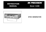
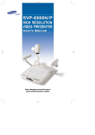
CML Semiconductor Products Evaluation Kit User Manual EV6040 UM6040/3 December 1996 1.0 Features • For FX604 Product Evaluation • User's Prototyping Area • Reconfigurable Board with • Space for Optional and Telco- Advance Information Interface to Optional µ C Board Specific Components • Parallel Phone Detector • Single Power Supply Operation • Easy Access to Test Points • On-Board Regulator 1.1 Brief Description The EV6040 Evaluation Kit comprises a single board containing an FX604 and its associated line interface components. It communicates with the CML µC board (EV6000), or the user's own µC board, demonstrating the use of an FX604 in modem applications, when user programmed. The EV6040 board is powered from a single 8 - 35V dc power supply; an on-board regulator sets 3.3V or 5.0V operation. LEDs indicate data, control and interrupt line status (DET, RDYN, RXEQ, M0 and M1) and the FX604 may be driven from an external clock, or from its own crystal oscillator. Important signals can be monitored by test points. The FX604 is socketed for easy replacement; a ZIF socket may also be fitted. The FX614 may be substituted for Bell 202 modem applications. On-board relays may be used to implement a wetting pulse, to place an ac or dc load on the line, and to interface the line to a transformer/op-amp hybrid for modem communications. A mutable voice input and a µC controllable or pre-settable DTMF generator are provided; operation of both these and the relays are indicated by LEDs. The parallel phone detector may be used in adjunct box emulation. The FX604 supply current may be measured by removing a jumper. Where components are telcospecific (line impedance, line protection, ac-load, wetting pulse, etc.) space is provided for the user to add appropriate components. A user prototyping area is provided. Finally, with a different jumper configuration, an FX602 and appropriate µC firmware, the EV6040 board may be used for evaluating the FX602. The EV6020 manual is enclosed on disk. 1996 Consumer Microcircuits Limited Evaluation Kit User Manual for FX604 EV6040 CONTENTS Section Page 1.0 Features......................................................................................................1 1.1 Brief Description ........................................................................................1 1.2 Preliminary Information .............................................................................4 1.2.1 Laboratory Equipment ..................................................................4 1.2.2 Handling Precautions....................................................................4 1.2.3 Telephone Line Connection ..........................................................5 1.3 Quick Start..................................................................................................5 1.3.1 Setting-Up ....................................................................................5 1.3.2 Operation .....................................................................................5 1.4 Signal Lists.................................................................................................6 1.5 Circuit Schematics and Board Layouts ....................................................8 1.6 Detailed Description ................................................................................10 1.6.1 Hardware Description - Evaluation Board....................................10 1.7 Performance Specification ......................................................................12 1.7.1 Electrical Performance................................................................12 1996 Consumer Microcircuits Limited 2 UM6040/3 Evaluation Kit User Manual for FX604 EV6040 Figure 1 Block Diagram 1996 Consumer Microcircuits Limited 3 UM6040/3 Evaluation Kit User Manual for FX604 1.2 Preliminary Information 1.2.1 Laboratory Equipment EV6040 The following laboratory equipment is needed to use this evaluation kit: 1.2.1.1 8 - 35V DC Power Supply. 1.2.1.2 Telephone Line Simulator and Line Signal Generator. 1.2.1.3 A µC control board (such as a CML EV6000, which contains the PIC 16LC74JW (or similar) µC), together with firmware and a user interface. 1.2.2 Handling Precautions Like most evaluation kits, this product is designed for use in office and laboratory environments. The following practices will help ensure its proper operation. 1.2.2.1 Static Protection This product uses low power CMOS circuits which may be damaged by electrostatic discharge. Partially damaged circuits may function erroneously, leading to misleading results. Observe ESD precautions at all times when handling this product. 1.2.2.2 Contents - Unpacking Please ensure that you have received all of the items listed on the separate information sheet (EK6040) and notify CML within 7 working days if the delivery is incomplete. 1.2.3 Telephone Line Connection This Evaluation Kit is not approved for direct or indirect connection to any public telecommunication system. Users are advised to observe local statutory requirements which may apply to this product. 1996 Consumer Microcircuits Limited 4 UM6040/3 Evaluation Kit User Manual for FX604 1.3 EV6040 Quick Start This section provides instructions for users who wish to experiment immediately with the evaluation kit. A fuller description of the kit and its use appears later in this document. 1.3.1 Setting-Up THE EV6040 COMES PRE-CONFIGURED WITH AN FX604, SET FOR OPERATION AT 5.0V. The board should be interconnected to a suitable µC control board with a 20-way flat cable, as shown in the Block Diagram of Figure 1. If the EV6000 µC board is not used, then power will need to be applied separately to the EV6040 evaluation kit through connector J3. An RJ11 (US style) phone jack is provided for telephone line simulator connection. No board adjustments are required by the user, although a (≈ 600Ω) line termination will need to be fitted to R20 before the EV6040 kit can be used. Other, telco-specific, components may be added, as required. BEFORE APPLYING POWER, PLEASE CHECK THE FOLLOWING: When using the EV6040 board with the EV6000 µC board, it will be noted that each board has connections for a single 8 - 35V dc power supply. Only one board needs to be connected as power is supplied to the other board over the flat cable. Each board has its own power supply regulator chip, with a jumper to select 3.3V or 5.0V (default ) operation. MAKE SURE BOTH BOARDS HAVE THIS JUMPER SET TO THE SAME VOLTAGE. DAMAGE MAY RESULT IF THIS STEP IS NOT OBSERVED. DO NOT OPERATE EITHER BOARD WITH ITS VOLTAGE SELECTION JUMPER REMOVED. Ensure the component value jumpers on the evaluation board are correctly set for 3.3V or 5.0V operation. Please refer to Section 1.6.1.5 for further details. 1.3.2 Operation This evaluation kit has no inherent functionality without a µC control board and appropriate firmware. The evaluation board may be used independently of the µC board, if the user wishes to interface to a different type of µC. 1996 Consumer Microcircuits Limited 5 UM6040/3 Evaluation Kit User Manual for FX604 1.4 EV6040 Signal Lists CONNECTOR PINOUT - EVALUATION BOARD Connector Ref. Connector Pin No. Signal Name Signal Type J1 1, 2 VIN Power +ve power from external power supply. 3, 4 VSS Power 0V power from external power supply. 5 TX-DTMF I/P Enables Tx from the DTMF generator. 6 AC-LOAD I/P Controls the relay which applies an ac load across the line. 7 WETTING PULSE I/P Controls the relay which applies a wetting pulse across the line. 8 TX-LINE I/P Controls the relay which connects the transformer across the line. 9 D3 I/P Control Line "D3" to the DTMF generator. 10 D2 I/P Control Line "D2" to the DTMF generator. 11 D1 I/P Control Line "D1" to the DTMF generator. 12 D0 I/P Control Line "D0" to the DTMF generator. 13 604-M0 I/P FX604: Mode Select pin (M0) 14 604-M1 I/P FX604: Mode Select pin (M1) 15 604-RDYN O/P FX604: µC Interrupt (Data Ready) 16 604-DET O/P FX604: Detect pin 17 604-CLK I/P FX604: Rx Data Clock pin 18 604-RXD O/P FX604: Rx Data pin 19 604-TXD I/P FX604: Tx Data pin 20 604-RXEQ I/P Control Line to unmute the Local Voice input (TP18) & Select FX604 Equalisation 1, 2 - - Not Used. No connection needed. 3 A BI Bidirectional 'phone line (A = TIP) 4 B BI Bidirectional 'phone line (B = RING) 5, 6 - - Not Used. No connection needed. 1 VSS Power 0V power from external power supply. 2 VIN Power +ve power from external power supply. J2 J3 Notes: I/P = Input 1996 Consumer Microcircuits Limited O/P = Output 6 Description BI = Bidirectional UM6040/3 Evaluation Kit User Manual for FX604 EV6040 TEST POINTS - EVALUATION BOARD Test Point Ref. Default Measurement TP1 0V VSS connection. TP2 0V VSS connection. TP3 - FX602 RD input, pin 3. Not used on EV6040 evaluation board. TP4 - FX602 RT signal, pin 4. Not used on EV6040 evaluation board. TP5 - FX602 AOP signal, pin 5. Not used on EV6040 evaluation board. TP6 VDD/2 TP7 - FX604 RXFB signal, pin 6. TP8 - FX604 RXD output, pin 13. TP9 - FX604 CLK input, pin 12. TP10 - FX604 DET output, pin 14. TP11 - FX604 RDYN output, pin 15. Pull-up resistor R11 is included on-board. TP12 - FX604 TXD input, pin 11. TP13 3.3V or 5.0V VDD connection. TP14 8 - 35V VIN connection. TP15 VDD/2 Hybrid transmit output (Local Voice). TP16 VDD/2 Hybrid receive output (Remote Voice). TP17 VDD TP18 - Description Line signal after transformer. Parallel Phone Detector output. Hybrid transmit input. Used as a mutable Local Voice input. JUMPERS - EVALUATION BOARD Link Ref. Positions Default Position Description JP1 1-2 or 2-3 2-3 Sets R2 value for line reversal (default) or ring detect usage JP2 1-2 1-2 Disconnect to measure IDD of evaluation device. JP3 1-2 or 2-3 2-3 Sets VDD = 3.3V (1-2) or VDD = 5.0V (2-3) JP4 1-2 or 2-3 2-3 Sets FX602 input sensitivity for 3.3V or 5.0V operation. JP5 1-2 or 2-3 2-3 Sets FX602 input sensitivity for 3.3V or 5.0V operation. JP6 1-2 or 2-3 2-3 Sets FX604 input sensitivity for 3.3V or 5.0V operation. JP7 1-2 or 2-3 2-3 Sets FX604 output drive level for 3.3V or 5.0V operation. JP8_1,2 1-2 1-2 Disconnect to supply an external clock to JP8_1 (2). JP9_1,2, JP9_3,4 1-2 1-2 all o/c JP10 1-2 o/c 1996 Consumer Microcircuits Limited User selectable DTMF answerback code. (Default = "C"). Links the Parallel Phone Detector to connector J1:19. 7 UM6040/3 Evaluation Kit User Manual for FX604 1.5 EV6040 Circuit Schematics and Board Layouts Figure 2 Evaluation Board - Circuit Schematic 1996 Consumer Microcircuits Limited 8 UM6040/3 Evaluation Kit User Manual for FX604 EV6040 Figure 3 Evaluation Board - Layout 1996 Consumer Microcircuits Limited 9 UM6040/3 Evaluation Kit User Manual for FX604 EV6040 1.6 Detailed Description 1.6.1 Hardware Description - Evaluation Board 1.6.1.1 Line Protection Line protection is provided by R27 (47Ω), R28 (47Ω), D7 and D8 (both TISP4180 or TISP5180 or TPA150A12 or TPA150B12). These components are not fitted, but suitable values for UK applications are suggested in brackets. Wire links which bypass R27 and R28 will need to be cut if these resistors are fitted. 1.6.1.2 AC or DC Load An ac or dc load is provided by R30 (827Ω), R36 (1386Ω) and C10 (139nF). These components are not fitted, but suitable values for UK applications are suggested in brackets. This load is controlled by relay RLY3. A logic '1' on AC-LOAD (J1 pin 6) connects this load and illuminates the LED. 1.6.1.3 Wetting Pulse A wetting pulse load is provided by R26, which is not fitted. For UK applications, a suitable value may be in the region of 240Ω to 350Ω. The wetting pulse is controlled by relay RLY2. A logic '1' on WETTING PULSE (J1 pin 7) connects the wetting pulse load and illuminates the LED. 1.6.1.4 Transformer and Op-Amp Hybrid The transformer and op-amp hybrid are connected to the phone jack by relay RLY1. A logic '1' on TXLINE (J1 pin 8) connects the transformer to the phone jack and illuminates the LED. 1.6.1.5 Operating Voltage The selection of operating voltage (VDD = 3.3V or 5.0V) by jumper JP3 affects the choice of component values around the evaluation device. The following jumpers should be used to select appropriate component values: JP1, JP4, JP5, JP6 and JP7. All jumpers must be set the same way: use position 1-2 for VDD = 3.3V and position 2-3 for VDD = 5.0V operation. 1.6.1.6 Clock/Oscillator The evaluation device may use either an external clock or its own xtal oscillator. A 3.58MHz xtal is provided on-board for the latter method. Two jumpers JP8, which are normally fitted, select the xtal oscillator. An external clock may be supplied to JP8_1 (2) once the jumpers have been removed. The DTMF generator uses its own 3.58MHz xtal because the xtal oscillator is only operational when the generator is active and the evaluation device has a 'zero-power' mode (in which its xtal oscillator is disabled) preventing it from supplying a clock to the DTMF generator. 1.6.1.7 Ring/Line Reversal Detection Ring/line reversal detection is provided by components C3, C4, R1-R4 and D1-D4. The response time constant is set by components R5 and C5. The evaluation board has been fitted with suitable components for UK applications. See FX602 data sheet for further details. This function is not used on the FX604. 1.6.1.8 Parallel Phone Detection Parallel phone detection is provided by components C17, C19-C23, R25, R29, R34, R35, R50, D20, D21 and TR4-TR7. It only communicates with a µC control board if jumper JP10 is fitted (however, this is not possible when a FX604 is used). A >2ms negative-going pulse on TP17 signifies a phone line voltage drop of ≈ 4.5V; a 1ms negative-going pulse signifies a phone line voltage rise of ≈ 4.5V. 1.6.1.9 IDD Measurement The evaluation device IDD may be measured by removing jumper JP2 and replacing it with a multimeter. 1996 Consumer Microcircuits Limited 10 UM6040/3 Evaluation Kit User Manual for FX604 EV6040 1.6.1.10 DTMF Answerback Code The DTMF answerback code may be selected by an appropriate choice of the four jumpers JP9. Fitting a jumper sets that input to logic '0'. If not fitted, the input is pulled-up on-chip to logic '1'. Alternatively, all of the JP9 jumpers may be omitted and the DTMF generator may be driven from a µ C. A logic '1' on TX-DTMF (J1 pin 5) enables the generator and illuminates the LED. DTMF GENERATOR DECODE TABLE J1:9 (D3) J1:10 (D2) J1:11 (D1) 0 0 0 0 0 0 0 0 1 1 1 1 1 1 1 1 0 0 0 0 1 1 1 1 0 0 0 0 1 1 1 1 J1:12 (D0) 0 0 1 1 0 0 1 1 0 0 1 1 0 0 1 1 0 1 0 1 0 1 0 1 0 1 0 1 0 1 0 1 DTMF CODE D 1 2 3 4 5 6 7 8 9 0 # A B C 1.6.1.11 Line Impedance Matching Line impedance matching is provided by R20, which is not fitted. A resistor (value ≈ 600Ω) is required for the evaluation board to operate correctly. 1.6.1.12 Voice Mute A mutable local voice input is provided on test point TP18. A logic '1' on 604-RXEQ (J1 pin 20) unmutes the voice input, selects the FX604 equalisation and illuminates the LED. Access to voice signals is provided as follows: The hybrid receive output (Rx = remote voice) is located on test point TP16. The hybrid transmit output (Tx = local voice) is located on test point TP15. If a voice input is not required, test point TP18 should be connected to ground. 1.6.1.13 Evaluation Device FX602/FX604/FX614 If the evaluation device is an FX602 it should be fitted in socket U2 position 1 and jumper JP10 should be fitted. If the evaluation device is an FX604 or FX614 it should be fitted in socket U2 position 2 and jumper JP10 should be removed, thus disabling the parallel phone detector output. This output is still available on test point TP17. Figure 4 FX604 Configuration 1996 Consumer Microcircuits Limited 11 UM6040/3 Evaluation Kit User Manual for FX604 1.7 Performance Specification 1.7.1 Electrical Performance EV6040 Absolute Maximum Ratings Exceeding these maximum ratings can result in damage to the Evaluation Kit. Supply (VIN - VSS) Supply (VDD - VSS) Voltage on any connector pin to VSS (excluding J2 pins 3 and 4) Current into or out of VIN and VSS pins Current into or out of J2 pins 3 and 4 Current into or out of any other connector pin Storage Temperature Operating Temperature Min. -0.3 -0.3 -0.3 Max. 40.0 7.0 VDD + 0.3 Units V V V 0 -250 -20 -10 +10 +1.5 +250 +20 +70 +35 A mA mA °C °C Max. 35.0 5.5 +35 3.583125 Units V V °C MHz Operating Limits Correct operation of the Evaluation Kit outside these limits is not implied. Notes Supply (VIN - VSS) Supply (VDD - VSS) Operating Temperature External Clock Frequency Min. 8.0 3.0 +10 3.575965 Operating Characteristics For the following conditions unless otherwise specified: Evaluation Device and DTMF Generator Xtal Frequency = 3.579545MHz, VDD = 3.3V or 5.0V, Tamb = +25°C. Notes Min. Typ. Max. Units DC Parameters IDD 1 - - 200 mA AC Parameters Xtal/Clock Input to Evaluation Device 'High' pulse width 'Low' pulse width 2 2 100 100 - - ns ns µC Interface (Connector J1) Input logic "1" level Input logic "0" level Input leakage current (Vin = 0 to VDD) Input capacitance Output logic "1" level (lOH = 120µA) Output logic "0" level (lOL = 360µA) 3 3 3 3 4 4 80% 5.0 90% - 10 - 20% +5.0 10% VDD VDD µA pF VDD VDD 1996 Consumer Microcircuits Limited 12 UM6040/3 Evaluation Kit User Manual for FX604 Notes: 1. 2. 3. 4. EV6040 Not including any current drawn from the board connector pins by external circuitry. Timing for an external input to the XTAL/CLOCK pin. When µC pin is configured as an input. When µC pin is configured as an output. Operating Characteristics - Timing Diagrams For FX602/FX604/FX614 timing information and operating characteristics, refer to CML Data Sheets. CML does not assume any responsibility for the use of any circuitry described. No IPR or circuit patent licences are implied. CML reserves the right at any time without notice to change the said circuitry and this evaluation kit specification. Evaluation kits are supplied for the sole purpose of demonstrating the operation of CML products and are supplied without warranty. They are intended for use in a laboratory environment only and are not for re-sale, end-use or incorporation into other equipments. Operation of evaluation kits outside a laboratory environment is not permitted within the European Community. All software is supplied "as is" and is without warranty. It forms part of the evaluation kit and is licensed for use only in this kit, for the purpose of demonstrating the operation of CML products. Whilst all reasonable efforts are made to ensure that software contained in this product is virus free, CML accepts no responsibility whatsoever for any contamination which results from using this software and the onus for checking that the software is virus free is placed on the purchaser of this evaluation kit. CONSUMER MICROCIRCUITS LIMITED 1 WHEATON ROAD WITHAM - ESSEX CM8 3TD - ENGLAND Telephone: Telefax: e-mail: +44 1376 513833 +44 1376 518247 [email protected] http://www.cmlmicro.co.uk