1
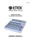
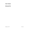
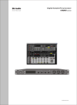
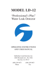
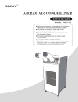
R
User M anual
ED-B3-MA-061012-001
Beta three
E200
E500
E300
E800
PROFESSIONAL POWER AMPLIFIER
-14
-16
-12
-10
-14
-16
-8
-6
-18
-4
-20
-24
-2
-12
-10
-8
-6
-18
-4
-20
-24
0
-2
0
E800
TO USERS
Thanks for choosing Series E power amplifier(s). Please read this manual carefully prior to use
of the product. Operation must be done strictly following the instructions stated in this manual.
Please consult your â 3 dealer or visit our website www.elderaudio.com for detailed information
when you have any questions.
TABLE OF CONTENTS
1.Precautions
P1
2.Performance Features
P1
3.Technical Specifications
P2
4.Installation Diagram
P6
5.Front Panel
P7
6.Rear panel
P7
7.Power Supply
P8
8.Input/Output Connection
P8
9.Function Setting and Signal Connection
P9
10.Operation Steps
P11
11.Description of Front Panel Indicators
P11
12.Protection Functions
P11
13.Troubleshooting
P12
1.PRECAUTIONS
Do not remove the cover to avoid high voltage hazard. Please refer servicing to qualified
personnel.
Do not explore the unit to rain or moisture.
Do not block the ventilation of the unit to ensure cooling efficiency.
Check whether the local voltage is identical with the operating voltage of the unit.
Please disconnect the unit from the power supply when it is not to be used for a long time.
Do not let the equipment run for a long time with overload.
Symbol Definition
The equilateral triangle containing a arrowheaded lightning symbol is intended to alert the
user of the presence of uninsulated ''angerous voltage'' within the equipment's enclosure
that may be of sufficient magnitude to constitute a risk of electric shock to persons.
The equilateral triangle containing a exclamation mark is intended to alert the user to the
presence of important operating and maintenance instructions in the literature accompanying
the appliance.
2.PERFORMANCE FEATURES
Series E products are high-performance big-power professional amplifiers which suit various
applications for sound reinforcement. The following shows the main features of Series E models.
1. High power output, big driving capacity.
2. Adoption of optimized heatsink structure and high quality cooling fans ensures system
reliability and allows the unit to run long hours with high power output.
3. Series E features interactive control over temperature of loaded impedance, power and
working voltage. Speed of the cooling fans can change automatically according to inner
temperature. When the loaded impedance is too low or the inner temperature is too high,
the equipment will adjust the power supply voltage and reduce the power supply impedance,
which helps to protect the system, and improve sound quality and reliability efficiently.
4. Low distortion
5. High slew rate helps to boost definition and achieve better sound
6. Low noise with the S/N ratio>108dB(A)
7. Frequency response: 20Hz-20KHz <+0/-0.25dB
8. 2U-rack compact design
9. E800 is specially designed for driving low impedance load, capable of driving 2 load for
a long time.
1
3.TECHNICAL SPECIFICATIONS OF E200
Stereo mode
Rated power
Parallel mono mode
Bridged mono mode
8
200W
4
300W
8
200W
4
300W
16
400W
8
600W
THD
<0.05%(10% rated power
Intermodulation distortion
<0.1%(60Hz/7KHz,10% rated power
Frequency response
20Hz~20KHz(+0/-0.25dB)
Phase deviation
< 15
Damping factor
>800(8 /100Hz)
Crosstalk
- 75dB
S/N ratio
>108dB(A weight)
Total gain
32
Channel gain error
<0.25dB
Input sensitivity
1V
Slew rate
>50V/ s
Input impedance
unbalanced 10K input, balanced 20K
Input connector
3-pin XLR/6.35 socket
Output connector
NL4 binding post
Cooling method
four stepless fans, front-to-rear airflow
Front panel control
AC power switch, channel 1/ channel 2 gain knob
Rear panel control
parallel/stereo/bridge mode option, lowcut/grouding/limit parameter selection
Front panel indicator
yellow-bridge, red-overload, green-signal
Amplifier protection
short circuit/DC/overheat/overload protection
Net dimensions
483
Net weight
12Kg
Power supply
AC 220V~230V,50~60Hz,250VA
Environmental temperature
work temperature:-10 ~40
Environmental moisture
0.5dB
310
input
88mm
90%
2
storage temperature:-25 ~80
3.TECHNICAL SPECIFICATIONS OF E300
Stereo mode
Rated power
Parallel mono mode
Bridged mono mode
8
300W
4
500W
8
300W
4
500W
16
600W
8
1000W
THD
<0.05%(10% rated power
Intermodulation distortion
<0.1%(60Hz/7KHz,10% rated power
Frequency response
20Hz~20KHz(+0/-0.25dB)
Phase deviation
< 15
Damping factor
>800(8 /100Hz)
Crosstalk
- 75dB
S/N ratio
>108dB(A weight)
Total gain
33.8
Channel gain error
<0.25dB
Input sensitivity
1V
Slew rate
>50V/ s
Input impedance
unbalanced 10K input, balanced 20K
Input connector
3-pin XLR/6.35 socket
Output connector
NL4 binding post
Cooling method
four stepless fans, front-to-rear airflow
Front panel control
AC power switch, channel 1/ channel 2 gain knob
Rear panel control
parallel/stereo/bridge mode option, lowcut/grouding/limit parameter selection
Front panel indicator
yellow-bridge, red-overload, green-signal
Amplifier protection
short circuit/DC/overheat/overload protection
Net dimensions
483
Net weight
14Kg
Power supply
AC 220V~230V,50~60Hz,400VA
Environmental temperature
work temperature:-10 ~40
Environmental moisture
0.5dB
375
input
88mm
90%
3
storage temperature:-25 ~80
3.TECHNICAL SPECIFICATIONS OF E500
Stereo mode
Rated power
Parallel mono mode
Bridged mono mode
8
500W
4
800W
8
500W
4
800W
16
1000W
8
1600W
THD
<0.05%(10% rated power
Intermodulation distortion
<0.1%(60Hz/7KHz,10% rated power
Frequency response
20Hz~20KHz(+0/-0.25dB)
Phase deviation
< 15
Damping factor
>800(8 /100Hz)
Crosstalk
- 75dB
S/N ratio
>108dB(A weight)
Total gain
36
Channel gain error
<0.25dB
Input sensitivity
1V
Slew rate
>50V/ s
Input impedance
unbalanced 10K input, balanced 20K
Input connector
3-pin XLR/6.35 socket
Output connector
NL4 binding post
Cooling method
four stepless fans, front-to-rear airflow
Front panel control
AC power switch, channel 1/ channel 2 gain knob
Rear panel control
parallel/stereo/bridge mode option, lowcut/grouding/limit parameter selection
Front panel indicator
yellow-bridge, red-overload, green-signal
Amplifier protection
short circuit/DC/overheat/overload protection
Net dimensions
483
Net weight
17Kg
Power supply
AC 220V~230V,50~60Hz,600VA
Environmental temperature
work temperature:-10 ~40
Environmental moisture
0.5dB
375
input
88mm
90%
4
storage temperature:-25 ~80
3.TECHNICAL SPECIFICATIONS OF E800
Stereo mode
Rated power
Parallel mono mode
Bridged mono mode
8
800W
4
1300W
8
800W
4
1300W
16
1600W
8
2500W
THD
<0.05%(10% rated power
Intermodulation distortion
<0.1%(60Hz/7KHz,10% rated power
Frequency response
20Hz~20KHz(+0/-0.25dB)
Phase deviation
< 15
Damping factor
>800(8 /100Hz)
Crosstalk
- 75dB
S/N ratio
>108dB(A weight)
Total gain
35
Channel gain error
<0.25dB
Input sensitivity
1V
Slew rate
>70V/ s
Input impedance
unbalanced 10K input, balanced 20K
Input connector
3-pin XLR/6.35 socket
Output connector
NL4 binding post
Cooling method
four stepless fans, front-to-rear airflow
Front panel control
AC power switch, channel 1/ channel 2 gain knob
Rear panel control
parallel/stereo/bridge mode option, lowcut/grouding/limit parameter selection
Front panel indicator
yellow-bridge, red-overload, green-signal
Amplifier protection
short circuit/DC/overheat/overload protection
Net dimensions
483
Net weight
20Kg
Power supply
AC 220V~230V,50~60Hz,900VA
Environmental temperature
work temperature:-10 ~40
Environmental moisture
0.5dB
378
input
88mm
90%
5
storage temperature:-25 ~80
4.INSTALLATION DIAGRAM
E800/E500/E300:
Æ
Æ
Á
ø
·
÷
½
Ï
ò
4 33
ø
Á
÷
·
Ï
½
ò
m
.0m
76.2mm
376mm
371mm
465.7mm
360.5mm
465
37
m
.0m
35
5m
m
6m
m
Æ
87.9
Á
ø
·
÷
Ï
½
ò
mm
o
rfl
Ai
w
482
m
.4m
E200:
Æ
Æ
Á
ø
·
÷
Ï
½
ò
433
Á
ø
·
÷
Ï
½
ò
m
.0m
76.2mm
310mm
302.5mm
298mm
292.5mm
46 5
31
30
3m
0m m
m
Æ
87.9
mm
Ai
6
m
.0m
o
rfl
w
48 2
.4m
m
ø
Á
÷
·
½
Ï
ò
5.FRONT PANEL
4
Take E800 as an example.
5
3
-14
R
PRO DESIGN
-12
-10
-14
-8
-16
UA SERIES
-18
-12
-10
-16
-6
-8
-18
-6
BRIDGE
-20
-4
-20
-4
P E A K
-2
-24
SIGNAL
0
ON
-2
-24
0
CHA
CHB
POWER
BETA THREE
7
1
8
2
E800
6
9
1.Ventilation entrance
4.Bridged mode indicator
7.Power supply switch
2.Channel 1 signal indicator
5.Channel 2 overload indicator
8.Channel 1 gain pot
3.Channel 1 overload indicator
6.Channel 2 signal indicator
9.Channel 2 gain pot
6.REAR PANEL
Take E800 as an example.
1
6
2
7
12
CHA
BRIDGE IN
-
!
A
+
LF FILTER
MODE
SIGNAL GND
BRIDGE
50HZ
PIN2:
SIGNAL +
PARALLEL
25HZ
PIN3:
SIGNAL -
STEREO
5HZ
CLIPLIMITER
CHA OUTPUT
GROUND
OFF
OFF
ON
ON
OUTPUT ASSIGNMENT:
CHA: PIN 1+ : CHA SIGNAL
PIN 1 - : CHA GND
PIN 2+ : CHB SIGNAL
PIN 2 - : CHB GND
BRIDGE
INPUT
PIN1:
CHB: PIN 1+ : CHB SIGNAL
PIN 1 - : CHB GND
PIN 2+ :
PIN 2 - :
BRIDGE MONO OUTPUT:
CHA : PIN1+ : SIGNAL
CHB
3
10
8
RMS:
STERO:
BRIDGE:
4
CAUTION
RISK OF ELECTRIC SHOCK
DO NOT OPEN
DELAY
FUSE
T 15A/250V
+
POWER
CABLE
+
AC 220V 50/60Hz
900VA
B
-
PIN2+ : GND
8 1 000W 2
16 2 000W
41
83
600W2
200W
CHB OUTPUT
ELDER AUDIO MANUFACTORY
5
11
13
14
9
1.Channel 1 signal input (XLR connector)
8.Channel 2 signal input (XLR connector)
2.Channel 1 signal input (1/4'' mic socket)
9.Channel 2 signal input (1/4'' mic socket)
3.Work mode switch
10.Filter switch
4.Clip limiter switch
11.Grounding switch
5.Channel 2 signal output (binding post)
12.Channel 1 signal output (NL4 socket)
6.Channel 1 signal output (binding post)
13.Channel 2 signal output (NL4 socket)
7.Fuse
14.Power cable
7
7.POWER SUPPLY
Before connecting the power amplifier to the power supply, check whether the operating
voltage (AC 220V~230V, 50~60Hz) is identical with your local power supply and confirm
that neither the power supply socket nor the power cord is damaged. Remember to pull
the cord plug out of the outlet when the unit is turned off.
8.INPUT/OUTPUT CONNECTION
Input connection
The input XLR and 1/4'' mic sockets of the same channel are linked in parallel.
Signal can be input via any input socket, output via the other socket of the same channel
and then input to another power amplifier in daisy chain mode.
Too many stages of daisy chain may affect sound quality, so do not input signals via two
interfaces of the same channel.
Output connection
The output binding post and the NL4 socket of the same channel are linked in parallel.
Do not connect both outputs of the same channel with load simultaneously.
Connect the red (hot) binding post to the positive pole of loudspeaker and the black post
to the negative pole.
Connect the output end only with load that can match the power rating and load impedance
of the power amplifier.
8
9.FUNCTION SETTING AND SIGNAL CONNECTION
1. Setting of clip limiter switch
CLIP
LIMITER
When the switch is in OFF position, the clip limiter is turned off and the limiter circuit is out
of function. Excessive signal input in such situation will easily cause clipping distortion in
output signal and loudspeaker overloading.
OFF
ON
CLIP
LIMITER
When the switch is in ON position, the clip limiter is turned on. When there is excessive
signal input, the limiter circuit will work automatically to adjust the total gain to reduce
distortion and control the power output without affecting the instantaneous peak output.
This function offers loudspeaker protection capability while ensuring dynamic range of music.
OFF
ON
Switching on the clip limiter is recommended when use.
2. Setting of low cut switch
Turning the low cut switch to 50Hz position equals to add a 50Hz high-pass filter in series
into the input circuit, so signals below 50Hz will be attenuated properly, which can limit the
noneffective excursion of loudspeaker and reduce the distortion, as shown in the following
diagram.
LF FILTER
+1
0dB
50HZ
-1
-2
25HZ
-3
-4
5HZ
-5
-6
20
30
40 50 60 80 100
200
300 400 500
Hz
When the low cut switch is turned to 25Hz position, it is equal to add a 25Hz high-pass filter,
which will attenuate signals below 25Hz, as shown in the following diagram.
LF FILTER
+1
0dB
50HZ
-1
-2
25HZ
-3
-4
5HZ
-5
-6
9
20
30
40 50 60 80 100
200
300 400 500
Hz
9.FUNCTION SETTING AND SIGNAL CONNECTION
When the low cut switch is turned to 5Hz position, all
signals within the frequency range will be amplified
accordingly, as shown in the right diagram.
LF FILTER
+1
0dB
50HZ
-1
-2
25HZ
-3
-4
5HZ
-5
-6
1. Mode selection and signal connection
Connection diagram
20
30
40 50 60 80 100
200
300 400 500
Hz
1
3
2
TRS unbalanced
TRS asymetrique
TRS no balanceado
Unsymetriscbe jStereoklinke
XLR unbalanced
XLR asymetrique
unsymetri is che XLR
XLR no balanceado
Cable pin diagram
Ground
1
2
3
A.Stereo mode
Firstly turn the mode switch to STEREO position
on the rear panel, as shown in the picture on the
right.
MODE
Balanced
Symetrique
Symmetrisch
Balanceado
Unbalanced
inverting input -
Asymetrique
Unsymmetrisch
non-inverting input +
No balanceado
Ground
non-inverting input +
BRIDGE
PARALLEL
STEREO
In stereo mode, signals through Channel 1 and Channel
2 of the power amplifier are treated as independent
ones, which means that Channel 1 input signal will go
only to Channel 1 output, and the same is to Channel 2,
as shown in the diagram.
B.Parallel mono mode
Firstly turn the mode switch to PARALLEL position
on the rear panel, as shown in the picture on the right.
In parallel mono mode, signals through Channel 1
or Channel 2 of the power amplifier have the same
effect, which means that Channel 1 input signal will
go to both Channel 1 and Channel 2 outputs, and
the same is to Channel 2, as shown in the diagram.
But do not input signals simultaneously to both
Channel 1 and Channel 2.
Attention: Parallel mono mode described here is
only refered to the parallel mode of the input signals.
Please do not use the output connectors in parallel
mode.
C.Bridged mode
Firstly turn the mode switch to BRIDGE position
on the rear panel, as shown in the picture on the right.
In bridged mode, signal can be only input via
Channel 1. Signal input via Channel 2 will not make
any sound. The positive pole of Channel 1 output
is also the positive pole of the bridged circuit. The
positive pole of Channel 2 is the negative pole of
the bridged circuit, as shown in the diagram.
To avoid electric shock that can be caused by the dangerous high output voltage, please
turn off the equipment before connecting in bridged mode!
E800 power amplifier is recommended for driving 4 load in bridged mode.
10
10.OPERATION STEPS
Please follow the operation steps below when using the equipment.
1. Start the equipment
a.Set functions and do connection in accordance with the detailed information described
in item 9.
b.Check whether the output connection is short-circuited and the load impedance is too low.
c.Check whether the local voltage is identical with the operating voltage.
d.Make sure the power supply switch on the front panel is in the ''0'' position and the volume
is minimized.
e.Connect the equipment to the power supply, turn on the sound source equipment, preequipment, and effectors in sequence and confirm that all work normally.
f.Turn on the power supply switch (settled at ''1'' position ).
g.Adjust the volume by turning the knob clockwise to a proper position.
2. Turn off the equipment
a. Minimize the volume by turning the knob anticlockwise.
b. Turn off the power supply switch on the front panel (to ''0'' position).
c. Turn off the pre-equipment, effectors and sound source equipment in sequence.
11.DESCRIPTION OF FRONT PANEL INDICATORS
1. Flashing of the signal indicator indicates that there is signal output through the two channels.
2. Flashing of the peak indicator indicates that the input level is too high and the volume must
be attenuated.
3. If the peak indicator is on continuously, it indicates that the unit is in abnormal operation
condition which is possibly caused by too low impedance load, short circuit, or overheating.
The unit must be turned off for checking and debugging before being turned on again.
4. If the bridged mode indicator is on, it indicates that the power amplifier is already in bridged
mode.
12.PROTECTION FUNCTIONS
E Series power amplifiers feature full protection functions which can protect the power amplifier
and loudspeaker system against damage potentially caused by short circuit, DC output or
overheating trouble.
1. Short circuit protection:
When short-circuit problem occurs in the load end, the unit will automatically switch off the
signal input therefore protect the equipment effectively.
2. DC protection:
When there is DC element in the output signal resulting from malfunction of the unit, the
unit will automatically switch off the signal output therefore effectively protect the loudspeaker
system from the potential damage caused by DC element.
3. Overheat protection:
When the temperature of the heatsink is higher than the permitted level, the temperature
sensor inside in the power amplifier will inform the protection circuit to switch off the output
automatically, therefore avoid damage to the unit and harm to the user.
11
13.TROUBLESHOOTING
Description of failures
Troubleshooting guide
No.
1
Check whether the power plug of the unit and the power
supply socket are in bad contact.
2
Check whether there is AC 220V/230V 50Hz/60Hz voltage
output from the power supply socket.
3
Check whether the fuse on the rear panel is already burnt.
1
Check whether the music signal cables are in good contact.
2
Check whether both the power supply switch and the
volume pot of the music source equipment have been
turned on.
3
Check whether the volume pot of the power amplifier has
been turned on.
1
Check whether there is excessive-amplitude signal input
from the source equipment.
2
Check whether the CLIP LIMMITER switch is in ON position
3
Check whether there exists short circuit problem in the
load end connection and ensure the load impedance to
be proper. Turn on the power amplifier again when the
problems are solved.
LF sound is not enough.
1
Check and make sure that the LF FILTER switch is in LF
50Hz or LF 25Hz position.
One channel is silent in
paralleled mono mode.
1
Check and make sure that the MODE switch is in PARALLEL
position.
1
Check whether the input signal level is matchable. Increase
the input level if it is not enough.
2
Check and make sure that the MODE switch is in BRIDGE
position.
1
Check and make sure that the local voltage is identical
with the operating voltage of the unit.
1
Check and make sure that all settings and connections
of the unit are correct in accordance with the related
instructions in the user's manual.
2
Consult professional personnel in the local authorized â3
products servicing centre or visit our website:
www.elderaudio.com.
There is no sound. The
power supply indicator is off.
There is no sound.
The power supply indicator is
on but the SIG. indicator is off.
The CLIP (overload)
indicator is on, and
there is abnormal sound.
Output is weak
in bridged mode.
Fuss is burnt after the
unit is turned on.
Other failures.
12
R
User M anual
E SERIES
PROFESSIONAL POWER AMPLIFIER
www.elderaudio.com