1
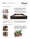
YRV (K3)
No. SB010202
SUBJECT:
CHECK AND ADJUSTMENT OF VALVE CLEARANCES IN YRV IN-VEHICLE
SERVICING OPERATION
We have received reports from some dealerships, in which they said that they were unable to perform the check
and adjustment of valve clearances in YRV in-vehicle servicing operation. Hence, we will issue a manual that describes the details of work procedures for them. Please use it as a version supplemental to Type K3 engine, as required.
Furthermore, we are advancing our revising of the maintenance schedule of the whole motor vehicle so that the
check and adjustment of valve clearances, too, may further be simplified.
OVERSEAS SERVICE DIVISION
1
CHECK AND ADJUSTMENT OF VALVE CLEARANCE
The following shows the in-vehicle check and adjustment procedures for the valve clearance. This information has been prepared based on the Type K3 Engine Service Manuals (No. 9737, 9232 and 9237) that
have been already published. Therefore, for tightening torque, disassembling and assembling procedures
that are not mentioned, please refer to these manuals.
1. Removal of air cleaner
The following is the removal/installation procedure for the air cleaner.
(1) Operations prior to removal
Disconnect the cable from the negative (–) terminal of the battery.
NOTE:
• It should be noted that the memories of the diagnosis results, radio, etc. will be erased at the
same time when the cable is disconnected from the negative (–) terminal of the battery.
(2) Removal and installation procedures
q
: Tightening torque
★
: Non-reusable parts
Unit : N·m
6.0 - 11.0
Charcoal canister
outlet hose No. 2
w
B
Air cleaner hose No. 1
6.0 - 11.0
B
r
B
Charcoal canister
outlet hose No. 1
t
B
6.0 - 11.0
6.0 - 11.0
e
q Air cleaner cap S/A with air cleaner hose No. 1
w Air cleaner element S/A
e Vacuum hose S/A
(Between intake manifold and pressure sensor)
r VSV (for purge control) with outlet hoses No. 1 & No. 2
t Air cleaner case S/A
(3) Main points of removal
(a) With the air cleaner hose No. 1 connected, remove the air cleaner cap subassembly q.
(b) Disconnect the connectors of pressure sensor and intake air temperature sensor. With the harnesses and hoses connected, remove the VSV for purge control r. Then, remove the air cleaner case subassembly t.
2
(4) Main points of installation
(a) Install the VSV for purge control t in such a way
that the outlet hoses No. 1 and No. 2 may not be
twisted, as indicated in the figure on the right.
(b) Install the vacuum hose subassembly e, as indicated in the figure on the right.
Charcoal canister
outlet hose No. 2
Charcoal canister
outlet hose No. 1
Vacuum hose S/A
2. Removal of washer tank
(1) Disconnect the two harness connectors leading to the
washer tank motor.
(2) Remove the two attaching bolts. Then, with the washer
hose connected, take out the washer tank and place it
between the hood and the windshield glass.
NOTE:
• Be sure to secure the washer tank by means of tapes,
etc. so that it may not fall down.
3. Remove the chain cover service hole screw plug, using a
hexagon wrench.
NOTE:
• It is recommended to use an L-shaped hexagon
wrench with a width across flats of 10 mm. (Approx.
50 mm × 180 mm)
L-shaped
hexagon
wrench
4. Remove the ignition coil cover and ignition coil.
5. Remove the cylinder head cover.
6. Turn the crankshaft in the normal direction, until the timing
mark (V notch) of the crankshaft pulley is aligned with the
indicator mark of the timing chain cover. (The cylinder
No. 1 comes to the top dead center.)
Service hole
7. Ensure that the mating marks of the camshaft timing
sprocket face upward. In cases where the mating marks
are not facing upward, turn the crankshaft one more turn.
Then, ensure that the mating marks are facing upward.
(The cylinder No. 1 comes to the top dead center under
the compression stroke.)
Mating marks
3
8. Check the valve clearance at the positions indicated in the
figure on the right, using a thickness gauge.
Valves to be checked at time when cylinder No. 1
comes to top dead center under compression stroke
Cylinder No. 1
Cylinder No. 2
Cylinder No. 3
Cylinder No. 4
IN
EX
IN
EX
IN
EX
IN
EX
!
!
!
—
—
!
—
—
9. Turn the crankshaft once so that the cylinder No. 1 comes
to the top dead center under the exhaust stroke. Then,
check the valve clearance at the positions indicated in the
figure on the right.
Valves to be checked at time when cylinder No. 1
comes to top dead center under exhaust stroke
Cylinder No. 1
Cylinder No. 2
Cylinder No. 3
Cylinder No. 4
IN
EX
IN
EX
IN
EX
IN
EX
—
—
—
!
!
—
!
!
10. If the measured value fails to conform to the specified
value, remove the camshafts No. 1 and No. 2. Then, adjust the valve clearance to the specified value by replacing the valve lifter, following the procedure given below.
NOTE:
• Be sure to record the position of the valve which failed
to conform to the specified value and the measurement
results.
• For the adjustment procedure, refer to the section EM
of the service manual described at the outset.
The following shows the in-vehicle removal and installation
procedures for the camshafts No. 1 and No. 2.
(1) As prior operations, prepare a mirror (a room mirror is
best fitted.), cloth, pen light and flat screwdriver whose
tip width is relatively small.
(2) As indicated in the illustration on the right, place the
room mirror on the cloth so that you can see the chain
cover service hole.
At this time, secure the pen light in such a way that it
can illuminate the service hole.
Stopper
plate
Chain cover
service hole
Pen light
Room
mirror
Cloth
4
(3) While observing the mirror, apply the flat screwdriver to
the hole of the stopper plate. Then, move it in the arrowheaded direction and hold it in a released state.
[Reference]
• Through this operation, the plunger of the tensioner will
be unlocked.
• If any difficulty is encountered in releasing the lock of
the stopper plate, slightly turn the stopper plate in right
and left directions, using the hexagon section for servicing of the camshaft.
• Since this operation must be carried out while looking
into the mirror, the actual operation becomes opposite
to that reflected in the mirror. Therefore, it is necessary
to get used to the operation.
(4) Slightly turn the camshaft to the right (normal turn),
using the hexagon section for servicing of the
camshaft, until the plunger section of the tensioner becomes in a pushed state by the chain.
(5) While holding the condition in Step (4), remove the flat
screwdriver from the chain cover service hole. Then,
insert a hexagon wrench with the hole of the stopper
plate aligned with that of the tensioner.
Tool: Hexagon wrench (Width Across Flats: 2.5 mm)
NOTE:
• The camshaft must be held, using the hexagon section
for servicing.
• Be sure to secure the hexagon wrench by means of a
tape, etc., so that it may not be pulled out.
[Reference]
• Through this operation, the plunger of the tensioner will
be held in a pushed state.
Chain cover
Hole of the
service hole
stopper plate
Room mirror
Flat screwdriver
5
(6) Remove the chain from the camshaft timing sprocket.
(7) Remove the camshaft timing sprocket, using the hexagon section for servicing of the camshaft.
NOTE:
• The chain will interfere with the sprocket, for the bolt is
loosened after the chain has been removed. Therefore,
be certain to securely hold the camshaft so that it may
not turn.
11. Assemble the camshafts No. 1 and No. 2.
For the assembling procedure, refer to the section EM of
the service manual described at the outset.
12. Install the cylinder head cover.
For the assembling procedure, refer to the section EM of
the service manual described at the outset.
13. Install the ignition coil and ignition coil cover.
For the assembling procedure, refer to the section EM of
the service manual described at the outset.
14. Install the chain cover service hole screw plug.
Perform the tightening, using the hexagon wrench (Width
across flats: 10 mm, L-shape (approx. 50 mm × 180 mm))
that was used during the removal.
15. Install the washer tank.
Tightening Torque: 6.0 - 11.0 N·m
16. Install the air cleaner.
For the assembling procedure, refer to page 1.
17. Connect the cable to the negative (–) terminal of the battery.
Return