1
Preface
This guide provides helpful information and instruction on how to configure VX-MD3024 system. All users should
carefully read this guide before handling this product and follow all instructions. For reader comprehension, this manual
contains detailed descriptions and practical examples of product configuration. This guide also provides the
information you need to configure Layer 2, Layer 3 features and VDSL features on your system. The system
administrator should be familiar with the concepts and terminology of Ethernet and Local Area Network (LAN) and
should have technical networking experience and professional knowledge about network equipment.
For detailed information about the VX-MD3024, contact the customer center at the www.versatek.com home page.
You can obtain the document about the VX-MD3024 and various information with questions.
※ Technical information in this guide is subject to change without notice
※ Copyright 2008 ⓒ Versa Technology, Inc.
※ All contents in this guide is protected under the copyright Laws.
Versa Technology, Inc.
VX-MD3024 Configuration Guide
Versa Technology, Inc.
xi
Preface
Organization
This guide is organized into these chapters:
Chapter 1, “Overview,” lists the software features of the release and provides examples of how the
system can be deployed in network.
Chapter 2, “Using the Command Line Interface” describes how to access the command modes, use the
command line interface (CLI), and describes CLI messages that you might receive. It also describes how
to get help, abbreviate commands, use no and default forms of commands, use command history and
how to search and filter the output of show and more commands.
Chapter 3, “Connecting to System and Assigning IP Address,” describes how to connect system and
explains how to assign IP address to be used for network communication.
Chapter 4, “Configuring System Environment,” explains how to configure system environment, manage
configurations and check the system. It also describes how to restart your system and make a
reservation of system rebooting.
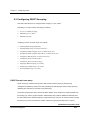
Chapter 5, “Configuring VDSL Feature,” describes how to configure the vdsl feature of each line. It also
explains how to upgrade modem image by using automatic and manual methods.
Chapter 6, “Configuring Switch Port Characteristics,” defines the type of Layer 2 and Layer 3 interfaces
on the system. It describes the interface command and provides procedures for configuring physical
interfaces.
Chapter 7, “Configuring VLAN,” describes how to create and maintain VLANs. It includes information
about the VLAN database, VLAN configuration modes. And it describes also how to add interfaces to a
VLAN and delete a interface from VLANs.
Chapter 8, “Configuring STP,” describes how to configure the Spanning Tree Protocol (STP) on your
system.
Chapter 9, “Configuring DHCP,” describes how to configure the Dynamic Host Configuration Protocol
VX-MD3024 Configuration Guide
Versa Technology, Inc.
xii
Preface
(DHCP) server and relay agent. It describes also how to configure DHCP snooping features those are
used for protected service.
Chapter 10, “Configuring Layer 2 Multicasting,” describes how to configure Internet Group Management
Protocol (IGMP) snooping. It includes information about IGMP Snoop Proxy.
Chapter 11, “Configuring IP Multicast Routing,” describes how to configure IP multicast routing. It
describes how to use and configure the Internet Group Management Protocol (IGMP) and IGMP Proxy.
Chapter 12, “Configuring filter with ACL,” describes how to configure filters on your system by creating IP
access control lists (ACLs).
Chapter 13, “Configuring QoS,” describes how to configure standard quality of service (QoS) on your
system. With this feature, you can preferential treatment to certain types traffic.
Chapter 14, “Configuring SNMP,” describes how to configure the Simple Network Management Protocol
(SNMP). It describes how to configure community strings, enable trap managers and traps.
Chapter 15, “Configuring System Message Logging,” describes how to configure system message
logging. It describes how to change the message display destination device, limit the type of messages
sent.
VX-MD3024 Configuration Guide
Versa Technology, Inc.
xiii
Preface
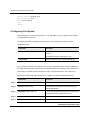
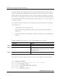
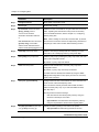
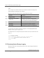
Conventions
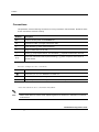
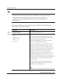
This publication uses the following conventions to convey instructions and information. Please be aware
of each command to use them correctly.
Notation
Description
abc
Command and keywords are in boldface text.
abc
Arguments for which you supply values are in italic.
[]
Square brackets ([ ]) mean optional elements.
<>
Range of number that you can use.
{}
Braces ({ }) group required choices, and vertical bar ( | ) separate the alternative elements.
[{ | }]
Braces and vertical bars within square brackets ([ { | } ]) mean a required choice within an
optional element.
Interactive examples use these conventions:
abc
Information you enter is in boldface screen font.
abc
Terminal sessions and system displays are in screen font.
<>
Nonprinting characters, such as passwords or tabs, are in angle brackets (< >).
Notes and cautions use these conventions and symbols:
Note
Means reader take note. Notes contain helpful suggestions or references to materials not contained
in this manual.
VX-MD3024 Configuration Guide
Versa Technology, Inc.
xiv
Preface
Caution
Means reader be careful. In this situation, you might do something that could result equipment
damage or loss of data.
VX-MD3024 Configuration Guide
Versa Technology, Inc.
xv
Chapter 1
Overview
This chapter describes the feature of VX-MD3024 system. It contains the following sections.
Features
Network Configuration Examples
Versa Technology, Inc.
VX-MD3024 Configuration Guide
1-1
Chapter 1
Overview
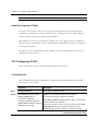
1.1 Features
This section describes the features supported in the VX-MD3024.
Performance
9
Auto-sensing of port speed and auto-negotiation of duplex mode on all switch ports for optimizing
bandwidth
9
IEEE 802.3X flow control on all Ethernet ports
9
Per-Port storm control for preventing broadcast, multicast, and unicast storms
Manageability
9
DHCP (Dynamic Host Configuration Protocol), which automatically assigns IP address to clients,
accessed to network. You can effectively utilize limited IP source and lower cost to manage
network because DHCP server manages all IP addresses from center.
9
DHCP relay agent information (option 82) for subscriber identification and IP address
management
9
Support FTP and TFTP for administering software upgrades and configuration information
management.
9
Network Time Protocol (NTP) for providing a consistent timestamp to all systems from an external
source
9
In-band management access through up to five simultaneous Telnet connections for multiple
command-line interface (CLI)-based sessions over the network.
9
In-band management access for up to five simultaneous, encrypted Secure Shell (SSH)
connections for multiple CLI-based sessions over the network.
9
In-band management access through Simple Network Management Protocol (SNMP) version 1
and 2c get and set requests.
9
Out-of-band management access through system console port to a directly attached terminal or to
a Console Server port which connected with the neighbor system.
9
Port entry guarantees for every subscribers connected with EX-5124B to get the same IP address
always. This feature makes you manage your subscribers more efficiently.
Redundancy
Versa Technology, Inc.
VX-MD3024 Configuration Guide
1-2
Chapter 1
Overview
9
IEEE 802.1D Spanning Tree Protocol (STP) for redundant backbone connections and loop-free
network. STP has these features:
−
Per-VLAN Spanning Tree (PVST) for balancing load across VLANs
−
UplinkFast for fast convergence after a spanning-tree topology change and for achieving load
balancing between redundant uplinks.
VLAN (Virtual Local Area Network)
9
Support for up to 1024 VLANs
9
Support for VLAN Ids in the full 1 to 4094 range allowed by the IEEE 802.1Q standard
Security
9
Password protected access to management interfaces for protection against unauthorized
configuration changes
9
Access host feature provides limited access from only allowed hosts those are configured with IP
address for Telnet, SNMP and SSH.
9
Bridge Protocol Data Unit (BPDU) guard for shutting down a Port Fast-configured port when an
invalid configuration occurs.
9
DHCP snooping for limiting and identifying MAC addresses and IP addresses of the stations
allowed to access the port.
9
ARP snooping protection for filtering invalid ARP packets those are sent from station which does
not have a valid IP address from the DHCP server with valid method.
Quality of Service (QoS) and Class of Service (CoS)
9
Classification
−
IP type-of-service/Differentiated Services Code Point (IP TOS/DSCP) and 802.1P CoS
marking priorities on a per-port basis for protecting the performance of mission critical
applications
−
TOS/DSCP and 802.1P COS marking based on flow-based packet classification
(classification based on information in the MAC, IP, and TCP/UDP headers) for highperformance quality of service at the network edge, allowing for differentiated service levels
for different types of network traffic and for prioritizing missioin-critical traffic in the network
Versa Technology, Inc.
VX-MD3024 Configuration Guide
1-3
Chapter 1
Overview
9
Policing
−
−
Policing on a physical interface
Traffic-policing policies on the switch port for managing how much of the port bandwidth
should be allocated to a specific traffic flow
−
Egress Policing and Scheduling of Egress Queues. Four egress queues on all switch ports.
These queues can either be configured with the Weighted Round Robin (WRR) scheduling
algorithm or configured with one queue as strict priority queue and the other three queues for
WRR. The strict priority queue must be empty before the other three queues are serviced.
You can use the strict priority queue for mission-critical and time-sensitive traffic
Layer 3 Support
9
IP routing between VLANs (inter-VLAN routing) for full Layer 3 routing between two or more
VLANs, allowing each VLAN to maintain its own autonomous data-link domain
9
Fallback bridging for forwarding non-IP traffic between two or more VLANs
9
Static IP routing for manually building a routing table of network path information
9
Equal-Cost routing for load balancing and redundancy
9
Protocol-Independent Multicast sparse mode (PIM-SM) for multicast routing within the network.
Monitoring
9
9
System LEDs that provide port and system level status
Syslog facility for logging system messages about authentication or authorization errors, resource
issues, and time-out events
9
9
Traffic counters those monitor the ingress or egress packet counters about various packet types.
VDSL event reporter and error counters those monitor the status of the line between CO and
CPEs and link status
Versa Technology, Inc.
VX-MD3024 Configuration Guide
1-4
Chapter 1
Overview
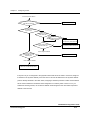
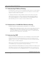
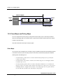
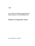
1.2 Network Configuration Examples
VX-MD3024 system using VDSL (Very-high-data rate Digital Subscriber Line) technology for
subscribers to be able to use PSTN service and Internet service simultaneously through already
distributed telephone lines. It is efficient for network providers or service providers to use EX-5124B by
reason of constructing network without new wiring. VX-MD3024 is suitable for hotel, apartment , or
building to provide upgraded network service.
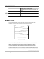
The following picture is an example of network construction using VX-MD3024. It is able to provide data
service and telephone service.
[ Example Configuration]
Versa Technology, Inc.
VX-MD3024 Configuration Guide
1-5
Chapter 2
Using the Command-Line Interface
This chapter describes CLI (Command Line Interface) that you can use to configure your systems. It
contains these sections:
Command Modes
Getting Help
Abbreviating Commands
Using Command History
Searching and Filtering Output of show Commands
Versa Technology, Inc.
VX-MD3024 Configuration Guide
2-1
Chapter 2 Using the Command-Line Interface
2.1 Command Modes
VX-MD3024 system’s user interface is divided into many different modes. The commands available to
you depend on which mode you are currently in. Enter a question mark (?) at the system prompt to
obtain a list of commands available for each command mode.
When you login successfully, you begin in user mode, often called user EXEC mode. Only a limited
subset of the commands are available in user EXEC mode.
To have access to all commands, you must enter Enable mode, often called privileged EXEC mode.
Normally, you must enter a password to enter Enable mode. From this mode, you can enter any
Enable mode commands or enter global configuration mode.
You can configure system functions for general system management and SNMP before configuring
specific protocol or specific function. From global configuration mode, you can enter interface
configuration mode and line configuration mode.
Using the configuration modes (global, interface, and line), you can make changes to the running
configuration. If you save the configuration, these commands are stored and used when the system
reboots.
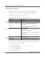
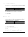
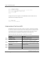
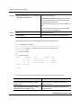
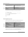
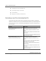
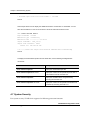
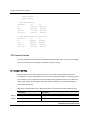
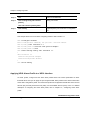
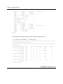
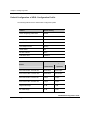
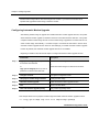
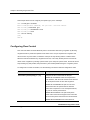
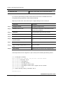
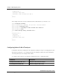
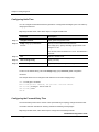
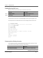
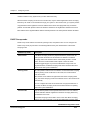
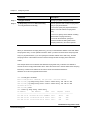
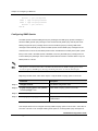
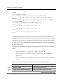
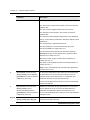
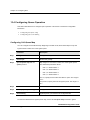
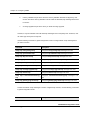
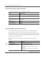
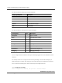
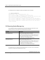
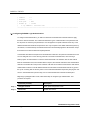
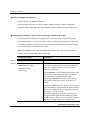
The following table describes the main command modes, how to access each one, and the prompt
you see in that mode.The examples in the table use the host name VX-MD3024.
[Table: Command Mode Summary]
Mode
Access Method
Prompt
User EXEC
Begin a session with your system
VX-MD3024>
While in user EXEC mode, enter the
VX-MD3024#
Enable
enable command
Global Configuration
While in Enable mode, enter the
VX-MD3024 (config)
configure command
VLAN Configuration
While in global configuration mode, enter
VX-MD3024 (config-vlan)
the vlan database command
Interface Configuration
While in global configuration mode, enter
VX-MD3024 (config-if)
the interface command (with a specific
interface)
Versa Technology, Inc.
VX-MD3024 Configuration Guide
2-2
Chapter 2 Using the Command-Line Interface
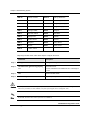
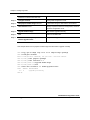
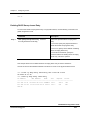
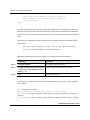
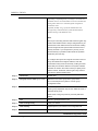
Line Configuration
While in global configuration mode,
VX-MD3024 (config-line)
specify a line with line vty or line console
command
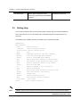
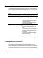
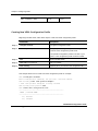
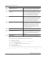
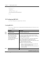
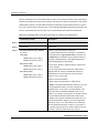
2.2
Getting Help
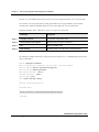
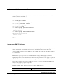
You can enter a question mark (?) at the system prompt to display a list of commands available for
each command mode. You can also obtain a list of associated keywords and arguments for any
command.
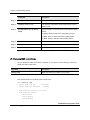
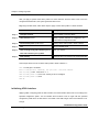
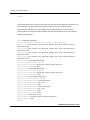
The following is the available commands on Enable mode of VX-MD3024 system.
VX-MD3024# ?
Exec commands:
clear
configure
Reset functions
Enter configuration mode
console-server execute console server
copy
Copy
debug
Debugging functions (see also 'undebug')
disable
Turn off privileged mode command
enable
Turn on privileged mode command
exit
End current mode and down to previous mode
help
Description of the interactive help system
kill
Kill(or terminate) Telnet or SSH Session
logout
Negate a command or set its defaults
ping
Send echo messages
quit
Exit current mode and down to previous mode
reload
Halt and perform a cold restart
remove
Remove file
restart
show
start-shell
telnet
(
Note
Exit from the EXEC
no
Restart routing protocol
Show running system information
Start shell
Open a telnet connection
)
Question mark (?) will not be seen in the screen and you do not need to press Enter key to display
Versa Technology, Inc.
VX-MD3024 Configuration Guide
2-3
Chapter 2 Using the Command-Line Interface
commands list. The displayed contents may vary depending on OS version.
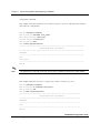
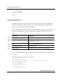
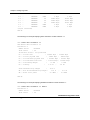
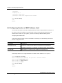
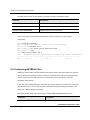
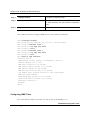
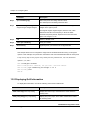
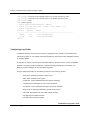
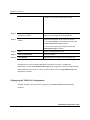
You can find out commands starting with specific character string. Input the specific string and
question mark without space. The following is an example of finding out commands starting with co in
Enable mode of VX-MD3024 system.
DUT-1# co?
configure
Enter configuration mode
console-server execute console server
copy
Copy
Also, it is possible to view variables you should input following after commands. After inputting the
command you need, make one space and input question mark. The following is an example of viewing
variables after the command copy. Please note that you must make one space after inputting.
DUT-1# copy ?
config
Configuration file
cpe-os-image CPE's OS Image
os-image
OS Image
2.3 Abbreviating Commands
You have to enter only enough characters for the system to recognize the command as unique. This
example shows how to enter the show running-config command in Enable mode.
DUT-1# sh run
2.4 Using Command History
In VX-MD3024 system, you do not have to enter repeated command again. When you need to use
Versa Technology, Inc.
VX-MD3024 Configuration Guide
2-4
Chapter 2 Using the Command-Line Interface
command history, you use up and down arrow key (↑ or ↓). When you press the up arrow key (↑),
the latest command you used will be seen one by one.
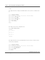
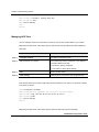
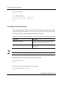
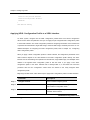
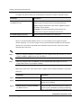
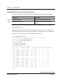
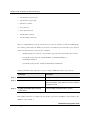
The following is an example of calling command history after using several commands. After using
these commands in order: show clock Æ configure terminal Æ interface fe1.1 Æ exit, press the up
arrow key (↑) and then you will see the commands from lastest one: exit Æ interface fe1.1 Æ
configure terminal Æ show clock.
DUT-1# show clock
2005-11-23 02:02:19 GMT+0900
DUT-1# configure terminal
Enter configuration commands, one per line. End with CNTL/Z.
DUT-1(config)# interface fe1.1
DUT-1(config-if)# exit
DUT-1# (press the up arrow key, ↑)
↓
DUT-1# exit (arrow key, ↑)
↓
DUT-1# interface fe1.1 (arrow key, ↑)
↓
Each time you press the up arrow
key, only the command is changed
on the same line.
DUT-1# configure terminal (arrow key, ↑)
↓
DUT-1# show clock
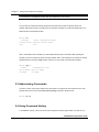
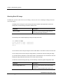
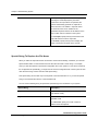
2.5 Searching and Filtering Output of show Commands
You can search and filter the output for show commands. This is useful when you need to select
through large amounts of output or if you want to exclude output that you don not need to see.
To use this functionality, enter a show or more command followed by the pipe character (|), one of the
keywords, begin, include, or exclude, and an expression that you want to search for or filter out:
command | {begin | include | exclude} regular-expression
Expressions are case sensitive. For example, if you enter | exclude output, the lines that contain
output are not displayed, but the lines that contain Output are displayed.
Versa Technology, Inc.
VX-MD3024 Configuration Guide
2-5
Chapter 2 Using the Command-Line Interface
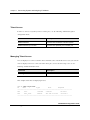
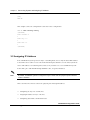
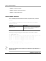
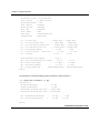
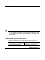
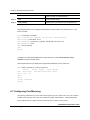
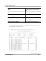
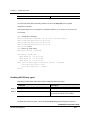
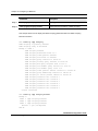
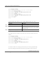
This example shows how to include in the output display only lines where the expression state
appears:
DUT-1# show spanning-tree | include state
%
fe1.1: designated port id 8003 - state Forwarding - priority 128
%
fe1.2: designated port id 8004 - state Forwarding - priority 128
%
fe1.3: designated port id 8005 - state Forwarding - priority 128
%
fe1.4: designated port id 8006 - state Forwarding - priority 128
%
fe1.5: designated port id 8007 - state Forwarding - priority 128
%
fe1.6: designated port id 8008 - state Forwarding - priority 128
%
fe1.7: designated port id 8009 - state Forwarding - priority 128
%
fe1.8: designated port id 800a - state Forwarding - priority 128
%
fe2.1: designated port id 800b - state Forwarding - priority 128
%
fe2.2: designated port id 800c - state Forwarding - priority 128
%
fe2.3: designated port id 800d - state Forwarding - priority 128
%
fe2.4: designated port id 800e - state Forwarding - priority 128
(output truncated)
Versa Technology, Inc.
VX-MD3024 Configuration Guide
2-6
Chapter 3
Connecting System and Assigning IP
Address
This chapter explains how to configure password for system connection and IP address for network
communication. You can connect to your system and use network service connected to equipments
by assigning IP address to interface and activating the interface.
It contains the following sections.
System Connection
Assigning IP Address
Versa Technology, Inc.
VX-MD3024 Configuration Guide
3-1
Chapter 3 Connecting System and Assigning IP Address
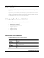
3.1 System Connection
This section describes how to configure your PC’s serial port, and change password for system
connection, connect to system through telnet as following order.
9
Configuring Serial Port on your terminal
9
System Login
9
Changing Password
9
Setting the Enable Mode Password
9
Password Encryption
9
Configuring Session Timeouts
9
User Management
9
Telnet Access
9
Managing Telnet Access
9
Displaying Access History
9
Configuring the number of connectable Telnet and SSH session
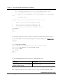
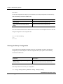
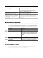
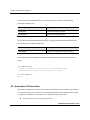
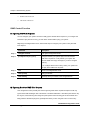
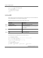
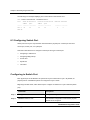
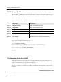
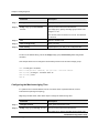
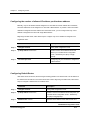
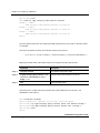
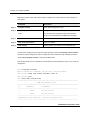
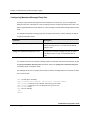
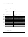
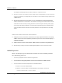
Configuring Serial Port on your terminal
After installing system, you can connect to the system through the console port. You must follow this
configuration in order to connect your PC’s seial port to system console port.
Feature
Setting
Baud rate
9600 bps
Data
8 bit
Parity check
None
Stop bit
1 bit
Versa Technology, Inc.
VX-MD3024 Configuration Guide
3-2
Chapter 3 Connecting System and Assigning IP Address
Flow control
none
System Login
After installing the VX-MD3024 system, ensure each port is correctly connected to PC for
network and management. And then, turn on the power and boot the system as follow.
When you turn on the system, booting will be automatically started and login prompt will be
displayed.
U-Boot 1.1.3 (Sep 3 2005 - 16:12:47)
CPU:
AMCC PowerPC 405EP Rev. B at 266.666 MHz (PLB=133, OPB=66, EBC=33
MHz)
IIC Boot EEPROM enabled
PCI async ext clock used, internal PCI arbiter enabled
16 kB I-Cache 16 kB D-Cache
Board: ASH405/EX21xxBD
I2C:
ready
DRAM: 256 MB
FLASH: 32.5 MB
Autobooting in 3 seconds, press "?????" to stop
Loading flash2...
Verifying Checksum ... OK
Uncompressing Multi-File Image ... OK
Loading Ramdisk to 0e21e000, end 0efff17b ... OK
Kernel loading... done.
System initializing... \Done
User Access Verification
username:
When you enter login ID at the login prompt, password prompt will be displayed. And enter
password to move into Enable mode. By default setting, login ID is configured as “root” and the
password is configured as “1234 ”
Versa Technology, Inc.
VX-MD3024 Configuration Guide
3-3
Chapter 3 Connecting System and Assigning IP Address
username: root
password: <1234>
DUT-1>
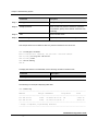
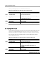
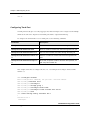
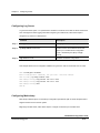
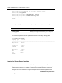
Changing Password
Administrators who can configure and manages can change system password. For thorough security,
you would better to change the password whenever necessary.
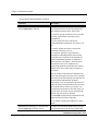
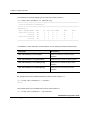
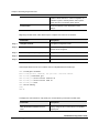
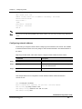
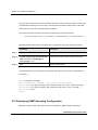
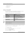
Beginning in Enable mode, follow these steps to set or change a static enable password.
Command
Description
Step 1
configure terminal
Enter global configuration mode.
Step 2
password
Change an existing password
Step 3
Enter the password
Enter the current password and new password to
change.
Step 4
exit
Return to Enable mode.
Step 5
write memory
(Optional) Save your entries in the configuration file.
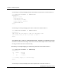
This example shows how to change password from 1234 to vdsl.
DUT-1# configure terminal
Enter configuration commands, one per line. End with CNTL/Z.
DUT-1(config)# password
Enter Current Password: <1234>
Enter New Password: <vdsl>
Confirm Password: <vdsl>
DUT-1(config)# exit
DUT-1#
Note
You can make password from at least 1 characters up to 31 characters. Please avoid similar one
withlogin ID.
Versa Technology, Inc.
VX-MD3024 Configuration Guide
3-4
Chapter 3 Connecting System and Assigning IP Address
Note
The password you enter will not be seen in the terminal, so please be careful. You need to enter the
password twice not to make mistake.
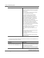
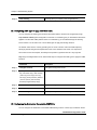
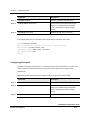
Setting the Enable Mode Password
You can set the Enable mode password that controls access to Enable mode. By default, EX-5124B
does not require the Enable mode password for entering the Enable mode.
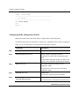
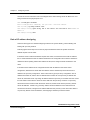
Beginning in Enable mode, follow these steps to configure enable password.
Command
Description
Step 1
configure terminal
Enter global configuration mode.
Step 2
enable password
Define a new password or change an existing password for
access to Enable mode.
Step 3
Enter the enable mode password
Enter new password and confirm it.
Step 4
exit
Return to Enable mode.
Step 5
write memory
(Optional) Save your entries in the configuration file.
This example shows how to change the Enable mode password to “vdsltest”.
DUT-1# configure terminal
Enter configuration commands, one per line. End with CNTL/Z.
DUT-1(config)# enable password
Enter New Password: <vdsltest>
Confirm Password: <vdsltest>
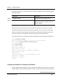
Password Encryption
All passwords on the system can be viewed by using the write terminal Enable mode command. If
Versa Technology, Inc.
VX-MD3024 Configuration Guide
3-5
Chapter 3 Connecting System and Assigning IP Address
you have access to Enable mode on the system, you can view all passwords in clear text by default.
You can hide clear-text passwords by storing passwords in an encrypted manner so that anyone
entering write terminal commands will not be able to determine the clear-text password.
Beginning in Enable mode, follow these steps to encrypt a user password.
Command
Description
Step 1
configure terminal
Enter global configuration mode.
Step 2
service password-encryption
Start password encryption mechanism
Step 3
exit
Return to Enable mode.
Step 4
write memory
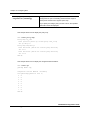
(Optional) Save your entries in the configuration file.
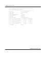
The following example shows how to start password encryption service and displaying the password
on the terminal line.
DUT-1# configure terminal
Enter configuration commands, one per line. End with CNTL/Z.
DUT-1(config)# service password-encryption
DUT-1(config)# enable password
Enter New Password: <test1>
Confirm Password: <test1>
DUT-1(config)#end
DUT-1#show running-config
!
service password-encryption
!
hostname DUT-1
!
enable password 7 $1$tup5$HdStUVH7YgBpm7dJoqhly1
!
(omitted)
Versa Technology, Inc.
VX-MD3024 Configuration Guide
3-6
Chapter 3 Connecting System and Assigning IP Address
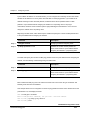
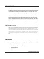
Configuring Session Timeouts
The timeout for an unattended telnet session or console session provides an additional security
measure. If the telnet line is left unattended in Enable mode, any user can modify the system
configuration. You can configure the timeout for console and telnet session separately.
The default timeout for an unattended telnet session is 10 minutes.
Beginning in Enable mode, follow these steps to change the login timeout.
Command
Description
Step 1
configure terminal
Enter global configuration mode.
Step 2
line console line-num
Enter the console-line configuration mode. You must set
or
line-num to 0, because the system supports only one
line vty line-num
Console session.
Enter the VTY-line configuration mode. Select line-num to
configure telnet session.
Step 3
exec-timeout minutes seconds
Set the login timeout.
The range of minutes is from 0 to 35791. The range of
seconds is from 0 to 2147483
If you set the login timeout to 0 0, automatic logout function
will be disabled.
If you want to disable automatic logout, enter exec-timeout
0 0 command.
Step 4
end
Return to Enable mode
Step 5
write memory
(Optional) Save your entries in the configuration file.
This example shows how to configure disabling automatic logout function for console, and change
the timeout for telnet session 0 to 4 to 20 minutes.
DUT-1# configure terminal
Enter configuration commands, one per line. End with CNTL/Z.
DUT-1(config)#line console 0
DUT-1(config-line)#exec-timeout 0 0
DUT-1(config-line)#exit
DUT-1(config)#line vty 0 4
Versa Technology, Inc.
VX-MD3024 Configuration Guide
3-7
Chapter 3 Connecting System and Assigning IP Address
DUT-1(config-line)#exec-timeout 20 0
DUT-1(config-line)#end
DUT-1#write memory
[OK]
DUT-1#
Note
You can access system through up to 3 telnet sessions simultaneously by default. You can change
the maximum number of allowed telnet sessions up to 5.
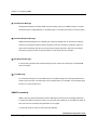
User Management
You can add a new user and remove an existing user. You must configure username and password pairs
to add new user. All users start with EXEC mode after login and must pass the authorization
procedures with the Enable mode password to move Enable mode.
Beginning in Enable mode, follow these steps to establish a username-based authentication system
that requests a login username and password:
Command
Description
Step 1
configure terminal
Enter global configuration mode.
Step 2
username name
Enter the user name
For name, specify the user ID for entering system.
Step 3
Enter Password
Specify the password for the user and confirm
Step 4
end
Return to Enable mode.
Step 5
show registered-user
Verify your entries.
Step 6
write memory
(Optional) Save your entries in the configuration file.
To disable username authentication for a specific user, use the no userna mename global
Versa Technology, Inc.
VX-MD3024 Configuration Guide
3-8
Chapter 3 Connecting System and Assigning IP Address
configuration command.
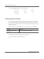
This example shows how to add a new user whose user ID is ‘test_user1’ and password is ‘tellion1’
and verifies the configuration:
DUT-1# configure terminal
DUT-1(config)# username test_user1
Enter New Password:<tellion1>
Confirm Password:<tellion1>
DUT-1(config)# exit
DUT-1#show registered-user
***********************************************************************
Registered User Information
***********************************************************************
Username
----------------------------------------------------------------------root
test_user1
----------------------------------------------------------------------DUT-1#
Note
The password you enter will not be seen in the screen, so please be careful not to make mistake.
This example shows how to remove a registered user whose user ID is ‘test_user1’.
DUT-1# configure terminal
DUT-1(config)# no username test_user1
DUT-1(config)# end
DUT-1# show registered-user
*******************************************************************
Registered User Information
*******************************************************************
Username
------------------------------------------------------------------root
------------------------------------------------------------------DUT-1#
Versa Technology, Inc.
VX-MD3024 Configuration Guide
3-9
Chapter 3 Connecting System and Assigning IP Address
Telnet Access
In order to connect to system by telnet at remote place, use the following commands in global
configuration mode.
Command
Description
telnet destination
Connects with IP address of another system.
telnet destination port-number
Connects with specified port of another port
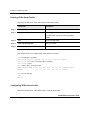
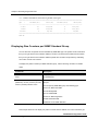
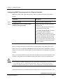
Managing Telnet Access
You can display users connected from remote and make some of them disconnected, as you want. In
order to display telnet users connected from remote place, before disconnecting a user, use the
following command in Enable mode.
Command
Description
show login-user
Show users connected.
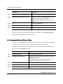
This example shows how to display login users.
DUT-1# show login-user
ID
User
Type
Host
Elapsed
------------------------------------------------------------------695
root
Console
console
01:15:27
826
test_user
Telnet
210.121.174.215
00:00:14
-------------------------------------------------------------------
Versa Technology, Inc.
VX-MD3024 Configuration Guide
3-10
Chapter 3 Connecting System and Assigning IP Address
You can disconnect a user connected from a remote location by using session ID which can be find with
show login-user command in Enable mode.
In order to disconnect a user connected with telnet, use the following command in Enable mode.
Command
Description
kill session session-id
Disconnect a user with session-id.
This example shows how to disconnect the remote connect user whose session ID is 826.
DUT-1# kill session 826
DUT-1#
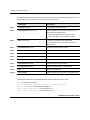
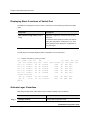
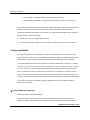
Displaying Access History
You can show the history about accessing your system. Use the following command to display history
of system access in Enable mode. In order to display the system access history, you must configure
system message logging to store the system access history information. You can refer to Chapter 15,
“Configuring System Message Logging” for more detailed information.
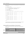
Command
Description
show log buffer login-history
Show the login history information
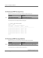
This example shows how to display the login history information.
DUT-1# show log buffer user-session
max-entry-size : 1000, current-entry-count : 607
Nov 23 11:21:47 <6> NSM: [CLI][LOGOUT]: user : root, remote-host : 210.121.174.215,
type : vty
Nov 23 11:21:42 <6> NSM: [CLI][LOGOUT]: user : test_user, remote-host:
210.121.174.215, type : vty
Nov 23 11:21:26 <6> NSM: [CLI][LOGIN]: user : test_user, remotehost :210.121.174.215, type : vty
Versa Technology, Inc.
VX-MD3024 Configuration Guide
3-11
Chapter 3 Connecting System and Assigning IP Address
Nov 23 11:20:54 <6> NSM: [CLI][LOGIN]: user : root, remote-host : 210.121.174.215,
type : vty
Note
You can show the login history only, when you configure the logging process to store the information
first.
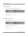
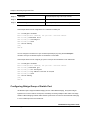
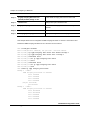
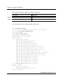
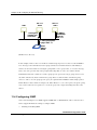
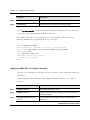
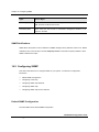
Configuring the number of connectable Telnet and SSH session
You can configure the maximum number of telnet sessions. By default, the maximum number of
telnet session is three, thus the only VTY-line 0 to 2 are active, and VTY-line 3 and VTY-line 4 are
disable. And all of SSH-line are disable.
Beginning in Enable mode, follow these steps to configure the number of maximum connectable
Telnet sessions and SSH sessions.
Command
Descriptioin
Step 1
configure terminal
Enter global configuration mode.
Step 2
line vty start-line end-line
Enter the VTY-line configuration mode. Specify the range of
or
line number with start-line and end-line
line ssh start-line end-line
Enter the SSH-line configuration mode. Specify the range of
line number with start-line and end-line
Step 3
end
Return to Enable mode.
Step 4
write memory
(Optional) Save your entries in the configuration file.
If you enter line vty 0 3 line configuration command, VTY-line 0 to 3 will be activate. And enter line
ssh 0 2 line configuration command to activate SSH-line 0 to 2. After enter above commands, you
can connect with four telnet (VTY-line 0 to 3) and three SSH (SSH-line 0 to 2) sessions
simultaneously.
You can disable the already activated line with no line vty 2 3 command or no line ssh 2 line
configuration command, if you want to reduce the maximum number of connectable Telnet or SSH
Versa Technology, Inc.
VX-MD3024 Configuration Guide
3-12
Chapter 3 Connecting System and Assigning IP Address
sessions.
This example shows how to configure the maximum number of telnet sessions to 5, and SSH sessions
to 3.
DUT-1# configure terminal
Enter configuration commands, one per line. End with CNTL/Z.
DUT-1(config)# line vty 0 4
DUT-1(config-line)# exit
DUT-1(config)# line ssh 0 2
DUT-1(config-line)# end
DUT-1# write memory
[OK]
DUT-1#
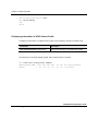
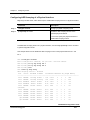
This example verifies the above configuration result.
DUT-1# show running-config
(omitted)
line console 0
!
line vty 0 4
!
line ssh 0 2
!
(omitted)
This example shows how to reduce the maximum number of telnet sessions to 3 and ssh sessions to
2 from the above configuration.
DUT-1# configure terminal
Enter configuration commands, one per line. End with CNTL/Z.
DUT-1(config)#no line vty 3 4
DUT-1(config)#no line ssh 2
DUT-1(config)#exit
DUT-1#write
Versa Technology, Inc.
VX-MD3024 Configuration Guide
3-13
Chapter 3 Connecting System and Assigning IP Address
[OK]
DUT-1#
This example verifies the configuration results after above configuration.
DUT-1# show running-config
(omitted)
line console 0
!
line vty 0 2
!
line ssh 0 1
!
(omitted)
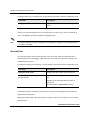
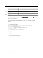
3.2 Assigning IP Address
If the VX-MD3024 system operates in Layer 2 switching mode, it uses only the data’s MAC address
to determine where traffic need to come from and which ports should receive the data. Systems do
not need IP addresses to transmit packets. However if you want to access to VX-MD3024 system
from remote place with TCP/IP through SNMP or telnet, it requires IP address.
Note
By default, VX-MD3024 system is configured to Layer 2 mode and all of physical ports included in
VLAN1.1 interface.
This section describes how to activate the physical port and assign IP address.
9
Configuring the Layer of each Interface
9
Assigning IP address to Layer 3 interface
9
Configuring Static Routes and Default router
Versa Technology, Inc.
VX-MD3024 Configuration Guide
3-14
Chapter 3 Connecting System and Assigning IP Address
Configuring the Layer of each Interfaces
As a default setting, all physical ports of VX-MD3024 system are configured Layer 2 mode. And all
physical ports are included in VLAN1.1 Layer 3 interface. If you want to use VX-MD3024 system to
Layer 2 mode, you just assign IP address to VLAN1.1 Layer 3 interface.
But, if you want to use VX-MD3024 system to Layer 3 mode, you must create new VLAN and assign
some physical ports to the new VDSL. And assign a IP address to the created VLAN.
If you want to more detailed information about configuring VLAN, you can refer chapter 7,
“Configuring VLAN”.
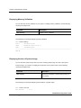
Assign IP address of Layer 3 Interface
Beginning in Enable mode, follow these steps to assign IP address to Layer 3 interface.
Command
Description
Step 1
configure terminal
Enter global configuration mode.
Step 2
interface if-name
Enter interface configuration mode. Specify the layer 3
interface to assign IP address.
Step 3
ip address ip-address/subnet-mask
Assign IP address and subnet mask to the layer 3
interface.
Step 4
end
Return to Enable mode.
Step 5
show ip interface brief
Verify your entries.
Step 6
write memory
(Optional) Save your entries in the configuration file.
This example shows how to assign IP address 192.168.100.10 to the VLAN1.1 interface and verify.
Versa Technology, Inc.
VX-MD3024 Configuration Guide
3-15
Chapter 3 Connecting System and Assigning IP Address
DUT-1# configure terminal
Enter configuration commands, one per line. End with CNTL/Z.
DUT-1(config)#interface vlan1.10
DUT-1(config-if)#ip address 192.168.100.10/24
DUT-1(config-if)#end
DUT-1#show ip interface brief
Interface
IP-Address
Status
Protocol
lo
127.0.0.1
up
up
vlan1.1
192.168.100.10 up
up
DUT-1#write memory
[OK]
DUT-1#
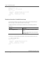
DHCP Client
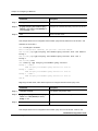
You can assign an IP address of a Layer 3 interface manually. You can use the DHCP client function
to assign an IP address to the specified Layer 3 interface.
Beginning in Privileged EXEC mode, follow these steps to configure a Layer 3 interface to be
assigned IP address using DHCP client.
Command
Description
Step 1
configure terminal
Enter the global configuration mode.
Step 2
interface interface-id
Enter interface configuration mode, and enter the Layer
3 interface to configure. The interface must be a Layer 3
interface.
Step 3
ip address dhcp
Configure the Layer 3 interface gets IP address
automatically with DHCP client function.
Step 4
end
Return to privileged EXEC mode.
Step 5
write memory
(Optional) Save your entries in the configuration file.
Versa Technology, Inc.
VX-MD3024 Configuration Guide
3-16
Chapter 3 Connecting System and Assigning IP Address
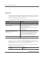
Configuring Static Routes and Default router
IP routing provided by VX-MD3024 system allows you to exchange traffic between different
networks and VLAN groups.
Specially, when you want to interconnect a bridged network with a routed network or another
bridged network, the layer 3 switching feature enables the switch to act as a true router. Configuring
static routes enables your system to route traffic over the network. Static routes are user-defined
routes that cause packets moving between a source and a destination to take a specified path. Static
route entries consists of the destination IP network address, the IP address of the next hop router.
Beginning in Enable mode, follow these steps to configure static routes.
Command
Description
Step 1
configure terminal
Enter global configuration mode.
Step 2
ip route ip-address/subnet-mask {ip-address
Establish static route. Specify IP address range of the
| interface-name}
remote network and the interface or IP address of the
next-hop router.
Step 3
Step 4
end
Return to Enable mode.
show ip route {ip-address | ip-address/M |
Verify your entries.
bgp | connected | database | isis | kernel |
ospf | rip | static}
Step 5
write memory
(Optional) Save your entries in the configuration file.
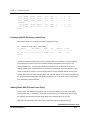
This example shows how to configure static routes on the system for the two nodes those are not
directly connected to.
DUT-1#configure terminal
Enter configuration commands, one per line. End with CNTL/Z.
DUT-1(config)#ip route 100.1.1.0/24 192.168.40.254
DUT-1(config)#ip route 100.2.2.0/24 192.168.40.254
DUT-1(config)#end
DUT-1#show ip route
Codes: K - kernel, C - connected, S - static, R - RIP, B - BGP
O - OSPF, IA - OSPF inter area
Versa Technology, Inc.
VX-MD3024 Configuration Guide
3-17
Chapter 3 Connecting System and Assigning IP Address
N1 - OSPF NSSA external type 1, N2 - OSPF NSSA external type 2
E1 - OSPF external type 1, E2 - OSPF external type 2
i - IS-IS, L1 - IS-IS level-1, L2 - IS-IS level-2, ia - IS-IS inter
area
* - candidate default
Gateway of last resort is 192.168.40.254 to network 0.0.0.0
S
100.1.1.0/24 [1/0] via 192.168.40.254, ge1
S
100.2.2.0/24 [1/0] via 192.168.40.254, ge1
C
192.168.40.0/24 is directly connected, ge1
C
192.168.101.0/24 is directly connected, vlan1.1
DUT-1#write
[OK]
DUT-1#
The following example shows how to configure the default network 0.0.0.0/0 through a default
gateway 192.168.40.254. The default route appears in the gateway display of the show ip route
command.
DUT-1#configure terminal
Enter configuration commands, one per line. End with CNTL/Z.
DUT-1(config)#ip route 0.0.0.0/0 192.168.40.254
DUT-1(config)#end
DUT-1#write
[OK]
DUT-1#
Use this command in Enable mode to remove the configured static route.
Command
Description
no ip route {ip-address | ip-address/M} [{ip-
Remove static route.
address | interface-name}]
This example shows how to remove the static route. You can specify only destination IP address
Versa Technology, Inc.
VX-MD3024 Configuration Guide
3-18
Chapter 3 Connecting System and Assigning IP Address
range to remove the static route.
DUT-1#configure terminal
Enter configuration commands, one per line. End with CNTL/Z.
DUT-1(config)#no ip route 100.1.1.0/24 192.168.40.254
DUT-1(config)#no ip route 100.2.2.0/24
DUT-1(config)#end
DUT-1#write
[OK]
DUT-1#
Versa Technology, Inc.
VX-MD3024 Configuration Guide
3-19
Chapter 4 Administrating System
This chapter describes how to configure system environment such as configuring host name and
setting date and time and so on. This chapter contains following sections
Configuring System Environment
Managing Configurations
Displaying System Information
Configuring Ping Monitoring Function
Restart System
Versa Technology, Inc.
VX-MD3024 Configuration Guide
4-1
Chapter 4 Administrating System
4.1 Configuration System Environment
This section describes the following items:
9
Configuring Date and Time
9
Configuring NTP (Network Time Protocol)
9
Configuring Time-Zone
9
Configuring Host Name
9
Configuring Default TTL
9
Managing the Output Redirection File
Configuring Date and Time
You can configure date and time on your system.
Beginning in Enable mode, follow these steps to configure date and time on your system.
Command
Descriptioin
Step 1
configure terminal
Enter global configuration mode.
Step 2
clock year month day hh mm ss
Configure date and time.
For year, specify the year. The range is 1999 to 2999.
For month, specify the month. The range is 1 to 12.
For day, specify the day. The range is 1 to 31.
For hh, specify the hour. The range is 0 to 23.
For mm, specify the minute. The range is 0 to 59
For ss, specify the second. The range is 0 to 59.
Step 3
exit
Return to enable mode.
Step 4
write memory
(Optional) Save your entries in the configuration file.
This example shows how to set the system clock to 1:41 p.m. on November 24, 2005:
Versa Technology, Inc.
VX-MD3024 Configuration Guide
4-2
Chapter 4 Administrating System
DUT-1# configure terminal
Enter configuration commands, one per line. End with CNTL/Z.
DUT-1(config)# clock 2005 11 24 13 41 00
DUT-1(config)# exit
DUT-1#
To display the time and date configuration, use the show clock command in Enable mode. This
example shows how to display the system clock.
DUT-1# show clock
2005-11-24 13:46:10 GMT+0900
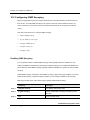
Configuring Network Time Protocol (NTP)
NTP (Network Time Protocol) can be used to configure your systems to 1/1000 second to guarantee
the exact time on networks. The System and NTP server constantly transmit the message each other
to converge the correct time. It is very important to configure exact time to the system so that the
system operates properly. The details about NTP will be given at STD and RFC 1119.
Beginning in Enable mode, follow these steps to configure NTP on your system.
Command
Description
Step 1
configure terminal
Enter global configuration mode.
Step 2
ntp server ip-address
Specify NTP server’s IP address. You can configure
several NTP server by repeating this command.
Step 3
ntp query-interval <1-43200>
Configure the period try to send NTP packet to the NTP
server. The range is 1 to 43200, and the unit is minutes.
Step 4
service ntp
Enable NTP function.
Step 5
exit
Return to enable mode.
Step 6
write memory
(Optional) Save your entries in the configuration file.
Versa Technology, Inc.
VX-MD3024 Configuration Guide
4-3
Chapter 4 Administrating System
This example shows how to configure the system to synchronize its system clock with the clock of the
NTP server at IP address 203.255.112.96 and configure the period to synchronize to 10 minutes. And
enable NTP function.
DUT-1#configure terminal
Enter configuration commands, one per line. End with CNTL/Z.
DUT-1(config)#ntp server 203.255.112.96
DUT-1(config)#ntp query-interval 10
DUT-1(config)#service ntp
DUT-1(config)#exit
DUT-1#write memory
[OK]
DUT-1#
To display the NTP configuration on your system, use the show ntp command in Enable mode. This
example shows how to display NTP server configuration.
DUT-1#show ntp
+ NTP Service
: Enabled
+ NTP Query Interval : 10 minutes
+ NTP Server List
:
203.255.112.96
DUT-1#
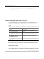
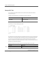
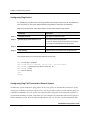
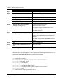
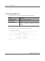
Configuring Time-Zone
You can configure Time-zone to your system. You must check Time-zone that you can configure..
The following table shows the kinds of Time-zone, which can configure to the system and a main
country or area, belong to the Time-zone.
Time Zone
Country
Time Zone
Country
GMT-12
Eniwetok
GMT+12
Wellington
GMT-11
Samoa
GMT+11
Okhotsk
Versa Technology, Inc.
VX-MD3024 Configuration Guide
4-4
Chapter 4 Administrating System
GMT-10
Hawaii, Honolulu
GMT+10
Sydney, Melbourne
GMT-9
Alaska
GMT+9
Seoul, Tokyo
GMT-8
LA, Seattle
GMT+8
Hong Kong, Peking
GMT-7
Denver
GMT+7
Bangkok, Singapore
GMT-6
Chicago, Dallas
GMT+6
Rangoon
GMT-5
New York, Miami
GMT+5
New Dehli
GMT-4
George Town
GMT+4
Teheran
GMT-3
Rio De Janeiro
GMT+3
Moscow
GMT-2
Maryland
GMT+2
Cairo, Athens
GMT-1
Azones
GMT+1
Berlin, Rome
GMT+0
London, Lisbon
Beginning in Enable mode, follow these steps to configure Time-zone.
Command
Description
Step 1
configure terminal
Enter global configuration mode.
Step 2
clock time-zone {gmt-minus|gmt-plus}
Set the time zone.
hour
For hour, enters the hour offset from UTC. The range is
0 to 12.
Step 3
exit
Return to Enable mode.
Step 4
write memory
(Optional) Save your entries in the configuration file.
Caution
When you set the time zone on your system, the time and date of the system will be changed also.
Therefore you must set time and date on your system again, after setting time zone.
Note
By default, the time zone of the system is set to GMT+9.
Versa Technology, Inc.
VX-MD3024 Configuration Guide
4-5
Chapter 4 Administrating System
This example shows how to configure time zone as Seoul and displaying the system clock.
DUT-1#configure terminal
Enter configuration commands, one per line. End with CNTL/Z.
DUT-1(config)#clock time-zone gmt-plus 9
DUT-1(config)#exit
DUT-1#write memory
[OK]
DUT-1#show clock
2005-11-24 14:37:21 GMT+0900
DUT-1#
Configuring Host Name
Host name displayed on prompt is necessary to distinguish each device connected to network. In
order to configure or change host name of switch, use the hostname command in global configuration
mode.
Beginning in Enable mode, follow these steps to set the hostname of your system.
Command
Description
Step 1
configure terminal
Enter global configuration mode.
Step 2
hostname name
Manually configure your system name.
The default setting is VX-MD3024.
Step 3
exit
Return to Enable mode.
Step 4
write memory
(Optional) Save your entries in the configuration file.
When you set the system name, it is also used as the system prompt. To return to the default
hostname, use the no hostname command in global configuration mode.
This example shows how to set host name to DSLAM.
DUT-1#configure terminal
Enter configuration commands, one per line. End with CNTL/Z.
DUT-1(config)#hostname DSLAM
Versa Technology, Inc.
VX-MD3024 Configuration Guide
4-6
Chapter 4 Administrating System
DSLAM(config)#exit
DSLAM#write memory
[OK]
DSLAM#
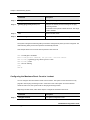
Configuring Default TTL
The default TTL value of the system is 64 generally. Thus the TTL value of the IP packets sent from
your system is 64 when you use ping or telnet on your system. But sometimes you should set the
larger TTL value according to the network configuration.
After you set the default TTL value to 128, the TTL of all packets sent from your system is set to 128.
Beginning in privileged EXEC mode, follow these steps to configure the default TTL value of your
system.
Command
Description
Step 1
configure terminal
Enter global configuration mode.
Step 2
ip ttl ttl-value
Specify the TTL value to configure. The default value is 64
and the range is 1 to 255.
Step 3
end
Return to Privileged EXEC mode.
Step 4
show running-config
Verify your entries.
Step 5
write memory
(Optional) Save your entries in the configuration file.
You can use the show ip ttl command in Privileged EXEC mode to display the TTL value configured in
your system.
This example shows how to set the TTL value to 128.
DUT-1#configure terminal
Enter configuration commands, one per line. End with CNTL/Z.
DUT-1(config)#ip ttl 128
DUT-1(config)#end
DUT-1#show running-config
(output truncated)
clock time-zone gmt-plus 9
Versa Technology, Inc.
VX-MD3024 Configuration Guide
4-7
Chapter 4 Administrating System
!
ip ttl 128
!
(output truncated)
DUT-1#write memory
[OK]
DUT-1#
Managing the Output Redirection File
You can use the redirection keyword to store the output to the specified file when you enter a
command. You can display the output files generated by using redirection function and remove the
files. And you can transfer the redirection files to the FTP or TFTP server using the copy command.
Use the following Privileged EXEC commands to display, remove and copy the output file generated
by using redirection.
Command
Description
show redirect-output
Display the redirection file lists stored in your system.
show redirect-output file-name
Display the contents of the specified redirection file.
remove redirect-output file-name
Delete the specified redirection file.
copy redirect-output src-file-name tftp ip-
Transfer the specified redirection file to the TFTP
address dest-file-name
server.
copy redirect-output src-file-name tftp ip-
Transfer the specified redirection file to the FTP
address user-id passwd dest-path
server.
4.2 Managing Configurations
You can check whether the configuration settings you entered are valid or not, and save them in the
configuration file. This section contains the following functions.
9
Checking the Running Configuration
Versa Technology, Inc.
VX-MD3024 Configuration Guide
4-8
Chapter 4 Administrating System
9
Saving the Running Configuration
9
Clearing the Startup Configuration
9
Save the Configuration to the Backup Configuration
9
Managing the Backup Configuration File
9
Copying Configuration Files by Using TFTP and FTP
Checking the Running Configuration
You can check the configuration settings you entered or changes you made by entering Enable mode.
This example shows the running configuration.
DUT-1#show running-config
!
service password-encryption
!
hostname DUT-1
!
username root password 8 4D1rxNdkiu1Eg
(output truncated)
line console 0
exec-timeout 0 0
line vty 0 2
exec-timeout 0 0
line ssh 0 1
!
end
Saving the Running Configuration
After you change system configuration, you must store it to the startup configuration in Flash memory.
If you do not store the changed configuration, the changed configuration will be lost when you restart
Versa Technology, Inc.
VX-MD3024 Configuration Guide
4-9
Chapter 4 Administrating System
your system.
To store the configuration or changes you have made to your startup configuration in Flash memory,
enter the following command in Enable mode.
Command
Description
write memory
Save your entries in the configuration file.
copy config running-config startup-
Save your entries in the configuration file.
config
Two commands described the above table do the same function. This example shows how to save the
changed configuration in the configuration file.
TELLION#write memory
[OK]
TELLION#
Clearing the Startup Configuration
You can remove the configuration changes one by one. Occasionally, you want to clear all of the
configuration you have changed. To clear the configuration file of your system, use the following
command in Enable mode.
Command
Description
copy config factory-default-config
clear the configuration file and make new
startup-config
configuration file with the factory default mode.
This example shows how to clear your configuration.
DUT-1#copy config factory-default-config startup-config
Versa Technology, Inc.
VX-MD3024 Configuration Guide
4-10
Chapter 4 Administrating System
OK..
startup-config would be applied AFTER system reboot.
DUT-1 #
Note
After you clear the startup configuration file, to operate with the cleared configuration, you must
reboot your system.
You may also want to keep the configuration information that is requested for communication with
system, even though you clear the configuration information on your system. VX-MD3024 system
supports the default configuration whose contents are same with the one of the factory default
configuration except the IP address assigned to Layer 3 interfaces, VLAN and static routing
information.
To clear the configuration except IP address, VLAN, and routing information, use the following
command in Enable mode.
Command
Description
copy config default-config startup-config
Clear the configuration except the IP addresses,
VLAN and static routing information.
This example shows how to clear the configuration except IP address assigned to the interfaces,
VLAN, and routing information on the system.
DUT-1#copy config default-config startup-config
OK..
startup-config would be applied AFTER system reboot.
DUT-1 #
Note
After you copy the default-config file to the startup-config file, you must restart your system for the
cleared configuration to be applied on your system.
Versa Technology, Inc.
VX-MD3024 Configuration Guide
4-11
Chapter 4 Administrating System
Save the Configuration to the Backup Configuration
You can save the running configuration to the backup configuration file. You can also use the backup
configuration file to recover system, when the configuration of your system is corrupted. Also you can
use the backup configuration file to configure other system easily.
To save the running configuration to the backup configuration file, use the following command in
Enable mode.
Command
Description
copy config running-config backup-
Save the running configuration to a backup
config name
configuration file.
For name, Enter the name of the backup
configuration file you save.
This example shows how to save your configuration to the backup configuration file.
DUT-1#copy config running-config backup-config tellion.conf
DUT-1 #
You can recover the configuration by using the backup configuration file that was saved already. To
recover the configuration file with the backup configuration, use the following command in Enable
mode.
Command
Description
copy config backup-config name startup-
Restore the configuration with the backup
config
configuration file whose file name is name.
This example shows how to store the configuration to the backup configuration file named tellion.conf.
Versa Technology, Inc.
VX-MD3024 Configuration Guide
4-12
Chapter 4 Administrating System
DUT-1#copy config backup-config tellion.conf startup-config
OK..
startup-config would be applied AFTER system reboot.
DUT-1 #
Managing the Backup Configuration File
You can copy, erase and display the stored backup configuration files.
To copy the backup configuration file to another backup file, use the following command in Enable
mode.
Command
Description
copy config backup-config name1
Copy the backup configuration file name1 to name
backup-config name2
2.
To delete the backup configuration file, use the following command in Enable mode.
Command
Description
remove backup-config name
Erase the backup configuration file named name.
To display the backup configuration files, use the following command in Enable mode.
Command
Description
show backup-config
Display the backup configuration file list.
This example shows how to copy, delete and display the backup configuration file. The first statement
copy the backup configuration file named tellion.conf to the other backup configuration file named
test.conf. The second statement displays the backup configuration file lists and the third statement
deletes the backup configuration file named test.conf.
Versa Technology, Inc.
VX-MD3024 Configuration Guide
4-13
Chapter 4 Administrating System
DUT-1#copy config backup-config tellion.conf backup-config test.conf
DUT-1#show backup-config
Filename
CreationTime
Filesize
--------------------------------------------------------------------------test.conf
2006-08-23 09:54:02
2914
tellion.conf
2006-08-23 09:54:16
2914
DUT-1#remove backup-config test.conf
DUT-1#
Copying Configuration Files by Using FTP and TFTP
You can configure the system by using configuration files you create or download from a TFTP or a
FTP server. You can upload the backup configuration files to a TFTP server or a FTP server for
storage.
To download or upload a configuration file by using TFTP, use the following command in Enable mode.
Command
Description
copy config backup-config name1 ftp ip-
Uploads the backup configuration file to a FTP
address user-id passwd name2
server.
copy config backup-config name1 tftp ip-
Uploads the backup configuration file to a TFTP
address name2
server.
copy config ftp ip-address user-id passwd
Downloads a configuration file from a FTP server.
name1 backup-config name2
copy config tftp ip-address name1 backup-
Downloads a configuration file from a TFTP server.
config name2
Before you begin to download or upload the backup configuration file using FTP or TFTP, you must
check the FTP server or TFTP server is properly configured. You must check the system has a
route to the TFTP or FTP server.
This example shows how to upload the backup configuration file named tellion.conf to the TFTP server
whose IP address is 192.168.100.51 and download the backup configuration file named test.conf from
Versa Technology, Inc.
VX-MD3024 Configuration Guide
4-14
Chapter 4 Administrating System
the FTP server whose IP address is 192.168.100.51.
DUT-1#copy config backup-config tellion.conf tftp 192.168.100.51
tellion.conf
DUT-1#copy config ftp 192.168.100.51 tellion tellion test.conf backupconfig test.conf
DUT-1#
Note
When you download or upload a configuration file by using TFTP or FTP, you can use only backup
configuration file. You cannot copy the download configuration to the running configuration file or
the startup configuration file.
4.3 Checking System
When there is any problem in system, the issue and its solution must be determined immediately.
Always check the system to prevent issues from occuring. Administrators should not only be aware of
the system status but should also check if configurations are correctly changed. This section includes the
following functions with command.
9
Checking Network Connection
9
Tracing Packet Route
9
Dump Packet
9
Managing MAC Table
9
Configuring Ageing Time
9
Managing ARP Table
9
Displaying System Uptime
9
Displaying Average CPU Utilization
9
Displaying Memory Utilization
Versa Technology, Inc.
VX-MD3024 Configuration Guide
4-15
Chapter 4 Administrating System
9
Displaying Version of System Image
9
Displaying Information of Installed System Image
9
Displaying System Environment Status
Checking Network Connection
You can use the ping command in Enable mode to check if your system is correctly connected to
the network.
In order to do ping test for checking network connection to the peer system, use the following
command in Enable mode.
Command
Description
ping [ip-address]
Sends an ICMP echo message to a designated IP
address for testing connectivity.
The following is an example of a ping test to check the network connection with 192.168.10.2.
DUT-1#ping 192.168.10.2
PING 192.168.10.2 (192.168.10.2) from 192.168.40.201 : 56(84) bytes of data.
64 bytes from 192.168.10.2: icmp_seq=1 ttl=254 time=0.902 ms
64 bytes from 192.168.10.2: icmp_seq=2 ttl=254 time=0.770 ms
64 bytes from 192.168.10.2: icmp_seq=3 ttl=254 time=0.777 ms
64 bytes from 192.168.10.2: icmp_seq=4 ttl=254 time=0.786 ms
--- 192.168.10.2 ping statistics --4 packets transmitted, 4 received, 0% loss, time 3022ms
rtt min/avg/max/mdev = 0.770/0.808/0.902/0.064 ms
Note
If you use ping command, the system send ping message continuously. To stop the ping test, you
must enter Ctrl-C Key.
Versa Technology, Inc.
VX-MD3024 Configuration Guide
4-16
Chapter 4 Administrating System
Extended Ping
When you enter the ping command, your system tries to send the ICMP Echo messages continuously
until you enter the Ctrl + C Key in the previous TOS version. You should not use the ping
command in the input file to be used to execute automatic CLI from this weak point.
When you enter the ping command in TOS 2.0.8, your system tries to send ICMP Echo messages just
4 times and finishes the command basically. You can configure also the count to try to send ICMP
Echo messages and configure the size of the ICMP Echo messages to be sent.
When you use the ping command to confirm the connection status between your system and the
other system, use the following command options in Privileged EXEC mode.
Command
Description
ping ip-address
Try to send ICMP Echo messages 4 times to the specified
IP address.
ping ip-address count count
Try to send ICMP Echo messages the number of specified
times.
For count, specify the number of times to try to send.
ping ip-address size size
Try to send ICMP messages of which length is specified 4
times.
For size, specify the length of the ICMP Echo message to
be sent. If you do not specify the size, the length of the
ICMP Echo message would be 56 by default. The range is
0 to 65507.
ping ip-address count count size size
Specify the number of times to try to send and the size of
the ICMP Echo messages
For count, specify the number of times to try to send.
For size, specify the length of the ICMP Echo message to
be sent. If you do not specify the size, the length of the
ICMP Echo message would be 56 by default. The range is
0 to 65507.
Versa Technology, Inc.
VX-MD3024 Configuration Guide
4-17
Chapter 4 Administrating System
Tracing Packet Route
You can discover the routes that packets will actually take when traveling to their destinations. To do
this, the traceroute command sends probe packets and displays the round-trip time for each node. If
the timer goes off before a response comes in, an asterisk (*) is printed on the screen.
To trace the route, use the following command in Enable mode.
Command
Description
traceroute ip-address
Traces packet routes through the network with
input IP address.
The following is an example of tracing packet route sent to 192.168.10.2.
DUT-1#traceroute 192.168.10.2
traceroute to 192.168.10.2 (192.168.10.2), 30 hops max, 40 byte packets
1 192.168.40.254 (192.168.40.254) 1.019 ms 1.788 ms 0.964 ms
2 192.168.10.2 (192.168.10.2) 1.34 ms * 1.128 ms
DUT-1#
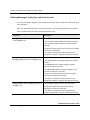
Dump Packet
(1) Dump the Header of Packets
You can dump the header of packets sent from your system and received on your system using the
dump-packet command in Privileged EXEC mode. Use the following Privileged EXEC commands to
dump the packets on interfaces of your system.
Command
Description
dump-packet {interface-name | any}
Dump the packets received on the specified interface or sent
to the interface.
For interface-name, specify the interface dumping packets.
You can specify Layer 2 interface or Layer 3 interface. If you
use any keyword instead of interface name, you can dump all
packets on every interfaces.
Versa Technology, Inc.
VX-MD3024 Configuration Guide
4-18
Chapter 4 Administrating System
dump-packet {interface-name | any} ethernet
Dump the packets of which the source MAC address is same
{mac-address | any }
with specified MAC address on the specified interface.
If you set any keyword instead of a specific MAC address, it
means the MAC address field is don’t care.
dump-packet {interface-name | any} ethernet
Dump the packets of which the source MAC address is same
{src-mac-address | any } {dest-mac-address |
with src-mac-address and the destination MAC address is
any }
same with dest-mac-address also on the specified interface.
If you set any keyword instead of a specific MAC address, it
means the MAC address field is don’t care.
dump-packet {interface-name | any} {arp |
Dump the ARP, DHCP, ICMP, IGMP or IP packets of which the
dhcp | icmp | igmp | ip | multicast} {src-ip-
source IP address is same with src-ip-address on the specified
address | any }
If you set any keyword instead of a specific IP address, it
means the IP address field is don’t care.interface.
dump-packet {interface-name | any} {arp |
Dump the ARP, DHCP, ICMP, IGMP or IP packets of which the
dhcp | icmp | igmp | ip | multicast} {src-ip-
source IP address is same with src-ip-address and the
address | any } {dest-ip-address | any }
destination IP address is same with dest-ip-address on the
specified interface.
If you set any keyword instead of a specific IP address, it
means the IP address field is don’t care.
dump-packet {interface-name | any} {tcp |
Dump the TCP or UDP packets of which the source IP address
udp} ip { src-ip-address | any }
is same with src-ip-address on specified interface.
If you set any keyword instead of a specific IP address, it
means the IP address field is don’t care.
dump-packet {interface-name | any} {tcp |
Dump the TCP or UDP packets of which the source IP address
udp} ip { src-ip-address | any } { dest-ip-
is same with src-ip-address and the destination IP address is
address | any }
same with dest-ip-address on specified interface.
If you set any keyword instead of a specific IP address, it
means the IP address field is don’t care.
dump-packet {interface-name | any} {tcp |
Dump the TCP or UDP packets of which the source IP address
udp} ip { src-ip-address | any } { dest-ip-
and the destination IP address is same with specified IP
address | any } portnum {port-number | any }
addresses and the source port number is same with specified
one.
If you set any keyword instead of a specific IP address, it
means the IP address field is don’t care.
dump-packet {interface-name | any} {tcp |
Dump the TCP or UDP packets of which the source IP address
udp} ip { src-ip-address | any } { dest-ip-
and the destination IP address is same with specified IP
Versa Technology, Inc.
VX-MD3024 Configuration Guide
4-19
Chapter 4 Administrating System
address | any } portnum {port-number | any }
addresses and the source port number and the destination
{port-number | any }
number are same with specified numbers.
If you set any keyword instead of a specific IP address, it
means the IP address field is don’t care.
dump-packet {interface-name | any} {tcp |
Dump the UDP or TCP packets of which the source port
udp} portnum {port-number | any }
number is same with the specified one.
dump-packet {interface-name | any} {tcp |
Dump the UDP or TCP packets of which the source port
udp} portnum {port-number | any } {port-
number and the destination number port are same with the
number | any }
specified ports.
(2) Control the Display ing E thernet Header
Before you use the dump-packet command to dump the packets matched in the condition you specified,
you can configure that the Ethernet header of the packets to dump could be displayed. Beginning in
Privileged EXEC mode, follow these steps to display the Ethernet header of the dumping packets also
Command
Description
Step 1
configure terminal
Enter global configuration.
Step 2
dump-packet include-ethernet-header
Configure the option of the dump-packet command to
display Ethernet header of dumping packets. You can
not show the Ethernet header of packets to dump by
default.
Step 3
end
Return to Privileged EXEC.
Step 4
show dump-packet
Verify your entries.
Step 5
write memory
(Optional) Save your entries in the configuration file.
(3) Control the Display ing o f Raw D ata
You can dump the packets with the raw packet data. Beginning the Privileged EXEC mode, follow
these steps to configure whether the raw data will be displayed or not
Versa Technology, Inc.
VX-MD3024 Configuration Guide
4-20
Chapter 4 Administrating System
Command
Description
Step 1
configure terminal
Enter global configuration.
Step 2
dump-packet raw-data display-length
Configure the option of the dump-packet command to
display raw data of the dumping packets.
For display-length, specify the length of raw data to
display.
Step 3
end
Return to Privileged EXEC.
Step 4
show dump-packet
Verify your entries.
Step 5
write memory
(Optional) Save your entries in the configuration file.
If you don’t want to show the raw data of the packets to be dumped, use the no dump-packet rawdata command to disable dumping raw data function.
(4) Configuring the Number of Packets to Dump
When you run the dump-packet command, the system dumps the number of packets configured and
it would print out a prompt and return to waiting status to process the next command.
Beginning in Privileged EXEC mode, follow these steps to configure the number of packets to dump
when you run the dump-packet command.
Command
Description
Step 1
configure terminal
Enter global configuration mode.
Step 2
dump-packet count number
Configure the number of packets to dump when you run the
dump-packet command.
For number, specify the number of packets to dump. The
default value is 1024 and the range is 1 to 8192.
Step 3
end
Return to privileged EXEC mode.
Step 4
show dump-packet
Verify your entries.
Step 5
write memory
(Optional) Save your entries in the configuration file.
Versa Technology, Inc.
VX-MD3024 Configuration Guide
4-21
Chapter 4 Administrating System
Managing MAC Table
You can display the MAC table information to find a system that has a specific MAC address is
connected to which port.
To display the MAC address table, use the following command in Enable mode.
Command
Description
show bridge
Displays MAC table.
The following is an example of displaying MAC table.
DUT-1#show bridge
bridge
VLAN port
MAC
Discard
Type
1
10
ge1
0000.f076.ccc0
N
Dynamic
1
10
ge1
0001.0257.2a49
N
Dynamic
1
10
ge1
0001.028c.5ee9
N
Dynamic
1
10
ge1
0001.0297.6915
N
Dynamic
1
10
ge1
0002.4427.1af9
N
Dynamic
(output truncated)
DUT-1#
MAC addresses are recorded in MAC table can be divided to kinds of type. One type is dynamic MAC
address which is recorded in MAC address automatically by using source MAC address passing the
port. And the other is static MAC address that is recorded in MAC table manually. A static MAC
address is not deleted until you delete the MAC address manually. The static MAC address remains in
MAC table on your system after rebooting it.
Beginning in Enable mode, follow these steps to add a static MAC address on your system.
Step 1
Command
Description
configure terminal
Enter global configuration command
Versa Technology, Inc.
VX-MD3024 Configuration Guide
4-22
Chapter 4 Administrating System
Step 2
bridge 1 address MAC-Address {forward
Add a static MAC address.
| discard} port [vlan vlan-id]
For {forward | discard}, specify filtering type. discard
means the packet whose source MAC address is the
MAC address will be discarded.
For MAC-Address, specify the source MAC address to
add
For vlan, specify the VLAN ID. If you don’t enter vlan
vlan-id, the vlan-id is the default vlan.
Step 3
exit
Return to Enable mode.
Step 4
write memory
(Optional) Save your entries in the configuration file.
This example shows how to add a static MAC address, and display MAC table.
DUT-1#configure terminal
Enter configuration commands, one per line. End with CNTL/Z.
DUT-1(config)#bridge 1 address 000e.dc31.0011 forward fe1.1
DUT-1(config)#exit
DUT-1#write memory
[OK]
DUT-1#show bridge
bridge
VLAN port
MAC
Discard
Type
1
1
fe1.1
000e.dc31.0011
N
Static
1
10
ge1
0000.f076.ccc0
N
Dynamic
1
10
ge1
0001.0257.2a49
N
Dynamic
(output truncated!)
DUT-1#
To remove a MAC address in the MAC table, use the following command in Enable mode.
Command
Description
clear mac address-table {dynamic | static}
Delete all dynamic or static MAC addresses in a
bridge bridge-id
specified bridge-id.
clear mac address-table {dynamic | static}
Delete all dynamic or static MAC addresses in a
interface interface-id bridge bridge-id
specified interface.
Versa Technology, Inc.
VX-MD3024 Configuration Guide
4-23
Chapter 4 Administrating System
clear mac address-table {dynamic | static}
Delete all dynamic or static MAC addresses in a
vlan vlan-id bridge bridge-id
specified VLAN.
clear mac address-table {dynamic | multicast |
Delete a specified MAC address.
static} address MAC-address bridge bridge-id
This example shows how to delete MAC addresses in MAC table.
DUT-1#clear mac address-table static address 000e.dc31.0011 bridge 1
DUT-1#clear mac address-table dynamic interface fe1.1 bridge 1
DUT-1#clear mac address-table static vlan 10 bridge 1
DUT-1#clear mac address-table dynamic bridge 1
DUT-1#
Configuring Ageing Time
The system records MAC table to prevent broadcast packets from transmitting. And unnecessary MAC
address that does not response during specified time is deleted from the MAC table automatically. The
specified time is called aging time.
Beginning in Enable mode, follow these steps to configure aging time.
Command
Description
Step 1
configure terminal
Enter global configuration mode.
Step 2
bridge 1 ageing-time seconds
Specify the aging time. The default value is 300
seconds. The range is 10 to 1000000.
Step 3
exit
Return to Enable mode.
Step 4
write memory
(Optional) Save your entries in the configuration file.
This example shows how to configure the ageing time to 800 seconds.
DUT-1#configure terminal
Enter configuration commands, one per line. End with CNTL/Z.
Versa Technology, Inc.
VX-MD3024 Configuration Guide
4-24
Chapter 4 Administrating System
DUT-1(config)# bridge 1 ageing-time 800
DUT-1(config)# exit
DUT-1#write memory
[OK]
DUT-1#
Managing ARP Table
You can add ARP entries to the ARP table, and remove a entry from the ARP table on your system.
Beginning in Enable mode, follow these steps to add an ARP entry (IP address and MAC address) to
ARP table.
Command
Description
Step 1
configure terminal
Enter global configuration mode.
Step 2
arp ip-address mac-address
Add an ARP entry which is composed of a IP Address
and a MAC address manually.
For ip-address, specify IP address.
For mac-address, specify MAC address.
Step 3
exit
Return to Enable mode.
Step 4
write memory
(Optional) Save your entries in the configuration file.
This example shows how to add an ARP entry whose IP address is 192.168.40.101 and MAC address
is 00:0E:DC:31:00:AA.
DUT-1#configure terminal
Enter configuration commands, one per line. End with CNTL/Z.
DUT-1(config)#arp 192.168.40.101 00:0e:dc:31:00:aa
DUT-1(config)#exit
DUT-1#write memory
DUT-1#
Beginning in Enable mode, follow these steps to delete an ARP entry from the ARP table.
Versa Technology, Inc.
VX-MD3024 Configuration Guide
4-25
Chapter 4 Administrating System
Command
Description
Step 1
configure terminal
Enter global configuration mode.
Step 2
no arp ip-address
Delete an ARP entry whose IP address is ip-address.
For ip-address, specify the IP address of the ARP entry
for deleting.
Step 3
exit
Return to Enable mode.
Step 4
write memory
(Optional) Save your entries in the configuration file.
This example shows how to delete an ARP entry whose IP Address is 192.168.40.101.
DUT-1#configure terminal
Enter configuration commands, one per line. End with CNTL/Z.
DUT-1(config)#no arp 192.168.40.101
DUT-1(config)#exit
DUT-1#write memory
DUT-1#
To display ARP entries in the ARP table, use the following command in Enable mode.
Command
Description
show arp
Display ARP Table.
The following is an example of displaying ARP table.
DUT-1#show arp
--------------------------------------------------------------------------Address
HWtype HWaddress
Flags Mask
Iface
--------------------------------------------------------------------------192.168.40.101
ether
00:0E:DC:31:00:12
CM
vlan1.10
192.168.40.254
ether
00:01:02:57:2A:49
C
vlan1.10
--------------------------------------------------------------------------* Flags: C=complete, P=published, M=manual
---------------------------------------------------------------------------
Versa Technology, Inc.
VX-MD3024 Configuration Guide
4-26
Chapter 4 Administrating System
Displaying System Uptime
You can show the time how long your system has been running after booting.
To display running time of your system, use the following command in Enable mode.
Command
Description
show uptime
Display running time of your system after booting.
The following is an example of displaying system uptime.
DUT-1#show uptime
8 Hour(s) 5 Minute(s) 48 Second(s) Elapsed
DUT-1#
Displaying Average CPU Utilization
You can show the average CPU utilization of your system. To display CPU utilization, use the following
command in Enable mode.
Command
Description
show cpu-load
Display average CPU utilization.
The following is an example displaying average CPU utilization.
DUT-1#show cpu-load
MeasureTime
CPU-Load
------------------------------------------------------------------------5 Sec
1.60 %
1 Min
1.06 %
10 Min
0.89 %
DUT-1#
Versa Technology, Inc.
VX-MD3024 Configuration Guide
4-27
Chapter 4 Administrating System
Displaying Memory Utilization
You can show the memory utilization of your system. To display memory utilization, use the following
command in Enable mode.
Command
Description
show memory
Display memory utilization.
The following is an example displaying memory utilization.
DUT-1#show memory
Total
: 246730752 bytes
Used
: 181493760 bytes(73.56 %)
Free
:
65236992 bytes
--------------------------------------------------------------------------DUT-1#
Displaying Version of System Image
You can show the system image version, the time creating system image, and size of the system
Image running in your system. To display the information of the system image, use the following
command in Enable mode.
Command
Description
show version
Displaying information of system image running on
your system.
The following is an example displaying the information of system image.
DUT-1#show version
TOS version
Versa Technology, Inc.
: 2.1.7
VX-MD3024 Configuration Guide
4-28
Chapter 4 Administrating System
Hardware version : 1.2
LOT number
: 2006/04(YYYY/MM)
Image at flash1:
Image Name:
PPC405EP-EX2124PLUS v06.06.08-2251K
Created:
2006-06-08
13:52:09 UTC
Data Size:
13944981 Bytes = 13.3 MB
DUT-1#
Displaying Information of Installed System Image
You can store two OS image on your system, and you can select a booting OS image. Before you
select an OS image, you must verify the information of each OS image.
To display the information of each OS image in the flash memory, use the following command in
Enable mode.
Command
Description
show os-image flash flash-id
Display the information of OS images in the flash
memory.
For flash-id, specify the flash memory area number.
The range is 1 to 2.
The following is an example displaying the information of the OS image in the flash memory area 1.
DUT-1#show os-image flash 1
Image at flash1:
Image Name:
Created:
PPC405EP-EX2124P v06.06.08-2251
2006-06-08
13:52:09 UTC
Data Size: 13944981 Bytes = 13.3 MB
DUT-1#
Versa Technology, Inc.
VX-MD3024 Configuration Guide
4-29
Chapter 4 Administrating System
Displaying System Environment Status
You can show the internal temperature of the system and the status of the FAN. To display the system
environment status, use the following command in Enable mode.
Command
Description
show environment temperature
Displaying the internal temperature of the system.
show environment external
Displaying the status of external FAN or the
door status of the cabinet that contains VXMD3024 system
The following is an example displaying the FAN status, internal temperature, and the external FAN and
door status of the external cabinet.
DUT-1#show environment door
External installation's status informations
| External door
| Opened
DUT-1#show environment temperature
********************************************************************
System Temperature
********************************************************************
temperature : 41.50 Grad Celsius
-------------------------------------------------------------------DUT-1#
DUT-1#show environment power
Power unit status
| PSB Equipment
| Communication Status
| Power unit type
| EQUIPED
| Normal
| AC-type
| Operating power type
| AC
| Power change status
| Battery -> AC at 2006-09-29
| AC/DC Output Voltage
| 37.10 V
04:46:37
Versa Technology, Inc.
VX-MD3024 Configuration Guide
4-30
Chapter 4 Administrating System
| AC/DC Output current
| DC/DC 12V Output Voltage
| 1.50 A
| 12.19 V
| DC/DC 3.3V Output Voltage
| Temperature
| 3.29 V
| 47.00 Degrees Celsius
Battery status
| Output Voltage
| 7.00 V
| Over discharge
| Over discharge
| Charge status
| Charging Off
| Charging Temperature Range
| Temperature
| -10 ~ 60 Degrees Celsius
| -50.00 Degrees Celsius
DUT-1#
4.4 Configuring Ping Monitoring Function
You usually use ping packets to check the live status of systems consists of your network. If you
cannot communicate with your system by a problem happens in your system itself or other reason. If
the reason that you cannot communicate with a system is the system problem, you must go near the
system and fix the problem or reboot system. To solve this problem in VX-MD3024 system, it sends
ping packets to the default router periodically and monitors the response. When the continuous fail
count of ping test is over the threshold you have configured, the system reboot automatically.
This section describes the following functions:
9
Configuring Ping Period
9
Configuring Ping Fail Threshold to Restart System
9
Configuring Lockout Period of Ping Monitoring Function
9
Configuring the Maximum Reset Count to Lockout
9
Enable Ping Monitoring Function
9
Displaying Ping Monitoring Status
Versa Technology, Inc.
VX-MD3024 Configuration Guide
4-31
Chapter 4 Administrating System
Configuring Ping Period
It is possible that a system tries to send ping packets continuously increase too much the utilization of
CPU. Therefore you can set the interval between ping packets to reduce the CPU utilization.
Beginning in Enable mode, follow these steps to set the interval between ping packets.
Command
Description
Step 1
configure terminal
Enter global configuration mode.
Step 2
gateway-ping-check interval interval
Set the interval between ping tests
For interval, specify the ping test interval. The range is
10 to 86400. The default interval is 30 seconds.
Step 3
exit
Return to Enable mode.
Step 4
write memory
(Optional) Save your entries in the configuration file.
This example shows how to set the ping interval to 60 seconds.
DUT-1#configure terminal
Enter configuration commands, one per line. End with CNTL/Z.
DUT-1(config)#gateway-ping-check interval 60
DUT-1(config)#exit
DUT-1#write memory
[OK]
DUT-1#
Configuring Ping Fail Threshold to Restart System
VX-MD3024 system sends three ping packets in the every ping test, and decides whether the result
of ping test is failed or not. If you cannot receive any ping response packets, you decide this ping test
is failed. But sometimes you can get the fail result by traffic congestion of the network. To protect a
system from rebooting by traffic congestion, you can configure the continuous fail count of ping test
before rebooting system. Thus the system only reboot in the case that the system continuously fails
Versa Technology, Inc.
VX-MD3024 Configuration Guide
4-32
Chapter 4 Administrating System
the threshold count you have set.
Beginning in Enable mode, follow these steps to set the ping fail threshold count.
Command
Description
Step 1
configure terminal
Enter global configuration command.
Step 2
gateway-ping-check check-count count
Configure the ping fail threshold count to restart system.
For count, specify the ping fail threshold count to restart
system. The range is 10 to 86400. The default value is
5
Step 3
exit
Return to Enable mode.
Step 4
write memory
(Optional) Save your entries in the configuration file.
This example shows how to configure the ping fail threshold count to 3.
DUT-1#configure terminal
Enter configuration commands, one per line. End with CNTL/Z.
DUT-1(config)#gateway-ping-check check-count 3
DUT-1(config)#exit
DUT-1#write memory
[OK]
DUT-1#
Configuring Lockout Period of Ping Monitoring Function
If you configure to reboot whenever the system detect continuous ping fail count is over than you
configured threshold count, when the uplink port of the system is down, the system will reset
endlessly repeated. To solve this problem VX-MD3024 system lockout the ping monitoring function
when the reboot count by ping fail is over than the maximum reset count during the configured
period.
Beginning in Enable mode, follow these steps to configure the lockout period.
Versa Technology, Inc.
VX-MD3024 Configuration Guide
4-33
Chapter 4 Administrating System
Command
Description
Step 1
configure terminal
Enter global configuration mode.
Step 2
gateway-ping-check period period
Configure the lockout period for locking out the ping
monitoring function.
The default lockout period is 86400 seconds. The range
is 100 to 259200.
Step 3
exit
Return to Enable mode.
Step 4
write memory
(Optional) Save your entries in the configuration file.
The system manages the rebooting history information during lockout period you have configured. The
older rebooting history than lockout period is automatically removed.
This example shows how to set the lockout period to 7200 seconds.
DUT-1#configure terminal
Enter configuration commands, one per line. End with CNTL/Z.
DUT-1(config)#gateway-ping-check period 7200
DUT-1(config)#exit
DUT-1#write memory
[OK]
DUT-1#
Configuring the Maximum Reset Count to Lockout
You can configure also the maximum reset count to lockout. The system counts the reset count by
ping fail to lockout ping monitoring function. If the reset count of the system is over the allowed
maximum reset count, the system locks out the ping monitoring function.
Beginning in Enable mode, follow these steps to configure the maximum reset count.
Step 1
Command
Description
configure terminal
Enter global configuration mode.
Versa Technology, Inc.
VX-MD3024 Configuration Guide
4-34
Chapter 4 Administrating System
Step 2
gateway-ping-check max-reset count
Configure the maximum reset count.
The default maximum reset count is 5. The range is 1 to
15.
Step 3
exit
Return to Enable mode.
Step 4
write memory
(Optional) Save your entries in the configuration file.
This example shows how to set the maximum reset count during lockout period to 3.
DUT-1#configure terminal
Enter configuration commands, one per line. End with CNTL/Z.
DUT-1(config)#gateway-ping-check max-reset 3
DUT-1(config)#exit
DUT-1#write memory
[OK]
DUT-1#
Enable Ping Monitoring Function
The default the ping monitoring status is disabled. You can enable the ping monitoring function.
Beginning in Enable mode, follow these steps to enable the ping monitoring function.
Command
Description
Step 1
configure terminal
Enter global configuration mode.
Step 2
service gateway-ping-check
Enable the ping monitoring function.
Step 3
exit
Return to Enable mode.
Step 4
write memory
(Optional) Save your entries in the configuration file.
To disable the ping monitoring function, use the no service gateway-ping-check command in global
configuration mode. This example shows how to enable the ping monitoring function.
Versa Technology, Inc.
VX-MD3024 Configuration Guide
4-35
Chapter 4 Administrating System
DUT-1#configure terminal
Enter configuration commands, one per line. End with CNTL/Z.
DUT-1(config)#service gateway-ping-check
DUT-1(config)#exit
DUT-1#write memory
[OK]
DUT-1#
After being locked out the ping monitoring function, you should enable the ping monitoring function
again manually by using CLI command to make the ping monitoring function enable.
Displaying Ping Monitoring Status
You can show the ping monitoring status of your system. To display the ping monitoring status, use the
following command in Enable mode.
Command
Description
show gateway-ping-check
Display the ping monitoring status.
The following shows the example displaying the ping monitoring status.
DUT-1#show gateway-ping-check
+ Gateway ping check : ENABLED
- Ping Interval(*)
: 100 seconds
- Checking count(*)
: 3
- Maximum Reset Count(*) : 3
- Checking Period(*)
: 7200 seconds
c.f.) (*) means non-default values
+ Gateway information
- Default gateway #1 IP : 192.168.40.254
-> the last pinging is success
+ System reset by gateway ping check information
- System reset is unlocked
system reset due to gateway ping fail(2005/10/27 11:12:09)
DUT-1#
Versa Technology, Inc.
VX-MD3024 Configuration Guide
4-36
Chapter 4 Administrating System
4.5 Restart System
Upgrading OS image and other various reason cause the need for rebooting a system. This section
describes the following items about rebooting system.
9
Rebooting System
9
Selecting Boot OS Image
9
Scheduling a Rebooting System
Rebooting System
To reboot system, use the following command in Enable mode.
Command
Description
reload
Restart system
If you reboot system without saving the changed configuration, it will be lost. So you have to save the
changed configuration in the configuration file before rebooting. Not to make a mistake, VX-MD3024
system is supposed to inform to you the following message to ask if you really want to reboot
without saving configuration. If you want to save the configuration, press “y” key, if you want to
reboot without saving the configuration, press “n” key.
The following is an example reloading system.
DUT-1#reload
configuration is changed..
save configuration? (y/N): y
[OK]
reboot system? (y/n): n
DUT-1#
Versa Technology, Inc.
VX-MD3024 Configuration Guide
4-37
Chapter 4 Administrating System
Selecting Boot OS Image
VX-MD3024 system is able to have two OS Image, and you can select a booting OS Image from two
stored OS images.
To display which OS image is current booting OS image and which OS image will be used at next
booting time, use the following command in Enable mode.
Command
Description
show os-image
Display the current booting OS image and next
time booting OS image information.
The following is the example displaying booting OS image information.
DUT-1#show os-image
Current Booted OS Image : FLASH Bank 1
Next-time-Boot OS Image : FLASH Bank 1
DUT-1#
You can find the current using OS image is stored in Flash Bank 1 and it will be used for next time also.
You can change the next time booting OS image. Before you select the next time booting OS image,
you should check the information of OS images stored in each flash bank. You can select the next time
booting OS image with flash bank number or the name of the OS image.
To select the next time booting OS image, use the following command in global configuration mode.
Command
Description
boot-os-image flash flash-id
Select the next time booting OS image with flash
bank number.
For flash-id, specify the flash bank number. The
Versa Technology, Inc.
VX-MD3024 Configuration Guide
4-38
Chapter 4 Administrating System
range is 1 to 2.
boot-os-image image-name image-name
Select the next time booting OS image with the
name of the OS image.
For image-name, specify the name of the OS
image
This example shows how to select the next time boot OS image to the flash bank 2.
DUT-1#configure terminal
Enter configuration commands, one per line. End with CNTL/Z.
DUT-1(config)#boot-os-image flash 2
DUT-1(config)#exit
DUT-1#write memory
[OK]
DUT-1#show os-image
*******************************************************************
OS Image Information
*******************************************************************
Current Booted OS Image : FLASH Bank 1
Next-time-Boot OS Image : FLASH Bank 2
------------------------------------------------------------------DUT-1#
This example shows how to select the next time boot OS image with the name of the OS image.
DUT-1#show os-image flash 1
Image at flash1:
Image Name:
Created:
PPC405EP-EX2124P v06.06.08-2251
2006-06-08
13:52:09 UTC
Data Size: 13944981 Bytes = 13.3 MB
DUT-1#configure terminal
Enter configuration commands, one per line. End with CNTL/Z.
DUT-1(config)#boot-os-image image-name PPC405EP-EX2124P v06.06.08-2251
DUT-1(config)#exit
Versa Technology, Inc.
VX-MD3024 Configuration Guide
4-39
Chapter 4 Administrating System
DUT-1#write memory
[OK]
DUT-1#show os-image
Current Booted OS Image : FLASH Bank 1
Next-time-Boot OS Image : FLASH Bank 1
DUT-1#
Scheduling a Rebooting System
You can schedule a rebooting system to occur on the system at a later time (for example, late at night
or during the weekend when the system is used less), or you can synchronize a reboot network-wide
(for example, to perform a software upgrade on all systems in the network).
To configure you system to reboot at a later time, use one of the following commands in Enable mode.
Command
Description
reload in hours minutes
Schedule a rebooting system to take affect in the
specified minutes or hours and minutes
reload at year month day hour minute
Schedule a rebooting system to take affect at the
specified time.
Note
A scheduled reboot must take place within approximately 24 hours.
This example shows how to reboot the system in 2 hours 30 minutes
DUT-1#reload in 2 30
DUT-1#
This example shows how to reboot the system at a future time.
DUT-1#reload at 2006 11 25 3 30
DUT-1#
Versa Technology, Inc.
VX-MD3024 Configuration Guide
4-40
Chapter 4 Administrating System
You can cancel the scheduled rebooting. To cancel the rebooting schedule, use the following
commands in Enable mode.
Commands
Description
no reload in
Cancel the rebooting schedule.
no reload at
Cancel the rebooting schedule.
You can show the scheduled rebooting information. To display the scheduled rebooting information,
use the following command in Enable mode.
Command
Description
show reload
Display the scheduled rebooting information.
This example shows how to display the scheduled rebooting information and cancel a scheduled
reboot.
DUT-1#show reload
+ System is reloaded at 2006-11-30 11:20:00(YYYY-MM-DD HH:MM)
+ executed after 98 days 21 hours 11 minutes 57 seconds
DUT-1#no reload at
DUT-1#
4.6 Automatic CLI Execution
Sometimes you might want to execute some commands periodically. You can configure the automatic
CLI execution function to run a sequence of commands periodically or at the specified time every day.
To configure the automatic CLI execution function, supports the following functions.
Downloading Input File and Uploading Result File
Versa Technology, Inc.
VX-MD3024 Configuration Guide
4-41
Chapter 4 Administrating System
Scheduling the Execution of Automatic CLI
Special String To Replace the File Name
Special Command
Displaying the Information of Automatic CLI
Downloading an Input File and Uploading Result File
You must write an input file in which a series of commands to execute are written, to configure the
automatic CLI execution function. And you should download the input file to your system using FTP or
TFTP protocol from the server. Use the following Privileged EXEC commands to download the input
file to your system.
Command
Description
copy autocmd-input tftp ip-address src-file-
Download the input file from a TFTP server.
name dest-file-name
For ip-address, specify the IP address of a TFTP
server.
For src-file-name, specify the input file name in the
TFTP server.
For dest-file-name, specify the destination file name
will be stored in the system.
copy autocmd-input ftp ip-address user-id
Download the input file from a FTP server.
password src-file-name dest-file-name
For ip-address, specify the IP address of a FTP
server.
For user-id, specify an user-id that will be used for
downloading from the FTP server.
For password, specify the password of the user on
the FTP server.
For src-file-name, specify the input file name in the
FTP server.
For dest-file-name, specify the destination file name
stored in your system.
Versa Technology, Inc.
VX-MD3024 Configuration Guide
4-42
Chapter 4 Administrating System
You need the result file that includes the results created by execution the commands specified in the
input file to monitor your system status or the results of executed commands. Thus you can configure
your system to upload the result file to the FTP or TFTP server. Use the following Privileged EXEC
commands to configure your system to upload the result file after executing the commands specified in
input file.
Command
Description
copy autocmd-output src-file-name tftp ip-
Uploads the result file to a TFTP server.
address dest-file-name
For ip-address, specify the IP address of a TFTP
server.
For src-file-name, specify the output file name to
upload to the TFTP server.
For dest -path, specify the destination directory
name to store it on the TFTP server.
copy autocmd-output src-file-name ftp ip-
Uploads the result file to a FTP server.
address user-id password dest-path
For ip-address, specify the IP address of a FTP
server.
For user-id, specify an user-id that will be used for
uploading to the FTP server.
For password, specify the password of the user on
the FTP server.
For src-file-name, specify the output file name to
upload to the FTP server.
For dest-path, specify the destination directory
name to store it on the FTP server.
Scheduling the Execution of Automatic CLI
After downloading the input file to your system, you can configure the commands specified in the input
file to be executed once a day at the specified time or once at the specified time. And you can
schedule that the commands are executed every specific interval and execute the commands directly.
To configure the commands specified in the input file to be executed once a day at the specified time,
Versa Technology, Inc.
VX-MD3024 Configuration Guide
4-43
Chapter 4 Administrating System
use the following Privileged EXEC commands.
Command
Description
autocmd input-file every hour minute [output-
Configure the commands in the specified input file
file| no-output] [tftp ip-address]
to be executed once a day at every specific time
and upload the result file to the TFTP server.
For input-file, specify the file name of the input file
including commands list to execute at every
specified time.
For hour, specify the hour to execute the
commands listed in the input-file. The range is 0 to
23.
For minute, specify the minute to execute the
commands. The range is 0 to 59.
For output-file, specify the output file name
including the results displayed by the executed
commands. If the output-file is not specified, the
system automatically generate an output-file of
which the name is IP address + input file name +
the execution time. The IP address of the
automatically generated output file name is the IP
address of the vlan of which vlan ID is lowest on
the system.
You can send the output file to the specified TFTP
server after finishing the execution of the command
list in the input file automatically. The output file will
be removed automatically after sending it
successfully. If you don’t specify the tftp server, the
output file would not be uploaded to the server and
the output file will be stored in your system. You
can upload the output file the other time when you
want to send it to a server. And the output file will
be kept until your system is reloaded.
For no-output, specify this keyword instead of the
output file name to make no output file.
For ip-address, specify the IP address of a TFTP
server.
autocmd input-file every hour minute [output-
Configure the commands specified in the input file
file| no-output] [ftp ip-address user-id
to be executed once a day at every specific time
Versa Technology, Inc.
VX-MD3024 Configuration Guide
4-44
Chapter 4 Administrating System
password path]
and upload the result file to the FTP server.
For input-file, specify the file name of the input file
including command list to execute at the specified
time every day.
For hour and minute, specify the time to execute
the command listed in the input-file.
For output-file, specify the output file name
including the results displayed by executed
command. If the output-file is not specified, the
system automatically generate an output-file of
which the name is IP address + input file name +
the execution time. The IP address of the
generated output file name is the IP address of the
vlan of which vlan ID is lowest on the system.
You can send the output file to the specified FTP
server after finishing the execution of the command
list in the input file automatically.
For no-output, specify this keyword instead of the
output file name to make no output file.
For ip-address, specify the IP address of a FTP
server.
For user-id, specify an user-id that will be used for
downloading in the FTP server.
For password, specify the password of the user in
the FTP server.
For path, specify the directory name in which the
output file is stored.
To configure the commands specified in the input file to be executed once at the specified time, use
the following Privileged EXEC commands.
Command
Description
autocmd input-file at year month day hour
Configure the commands specified in the input file
minute [output-file| no-output] [tftp ip-address]
to be executed once at the specific time and upload
the result file to the TFTP server.
For input-file, specify the file name of the input file
including commands list to execute at the specified
Versa Technology, Inc.
VX-MD3024 Configuration Guide
4-45
Chapter 4 Administrating System
time.
For year, specify the year to execute the
commands listed in the input file. The range is 2000
to 2035.
For month, specify the month to execute the
commands. The range is 1 to 12.
For day, specify the day to execute the commands.
The range is 1 to 31.
For hour, specify the hour to execute the
commands. The range is 0 to 23.
For minute, specify the minute to execute the
commands. The range is 0 to 59.
For output-file, specify the output file name
including the results displayed by executed
commands. If the output-file is not specified, the
system automatically generate an output-file of
which the name is IP address + input file name +
the execution time. The IP address of the
generated output file name is the IP address of the
vlan of which vlan ID is lowest on the system.
You can send the output file to the specified TFTP
server after finishing the execution of the command
list in the input file automatically. The output file will
be removed automatically after sending it
successfully. If you don’t specify the tftp server, the
output file would not be uploaded to the server and
the output file will be stored in your system. You
can upload the output file the other time when you
want to send it to a server. And the output file will
be kept until your system is reloaded.
For no-output, specify this keyword instead of the
output file name to make no output file.
For ip-address, specify the IP address of a TFTP
server.
autocmd input-file file at year month day hour
Configure the commands specified in the input file
minute [output-file| no-output] [ftp ip-address
to be executed once at the specific time and upload
user-id password path]
the result file to the FTP server. If you don’t specify
the FTP server, the result file would not transfer to
the FTP server.
Versa Technology, Inc.
VX-MD3024 Configuration Guide
4-46
Chapter 4 Administrating System
For input-file, specify the file name of the input file
including command list to execute at the specified
time every day.
For year, specify the year to execute the
commands listed in the input file. The range is 2000
to 2035.
For month, specify the month to execute the
commands. The range is 1 to 12.
For day, specify the day to execute the commands.
The range is 1 to 31.
For hour and minute, specify the time to execute
the command listed in the input-file.
For output-file, specify the output file name
including the results displayed by executed
command. If the output-file is not specified, the
system automatically generate an output-file of
which the name is IP address + input file name +
the execution time. The IP address of the
generated output file name is the IP address of the
vlan of which vlan ID is lowest on the system.
You can send the output file to the specified FTP
server after finishing the execution of the command
list in the input file automatically.
For no-output, specify this keyword instead of the
output file name to make no output file.
For ip-address, specify the IP address of a FTP
server.
For user-id, specify an user-id that will be used for
downloading in the FTP server.
For password, specify the password of the user in
the FTP server.
For path, specify the directory name in which the
output file is stored.
To configure the commands specified in the input file to be executed every interval periodically, use the
following Privileged EXEC commands.
Versa Technology, Inc.
VX-MD3024 Configuration Guide
4-47
Chapter 4 Administrating System
Command
Description
autocmd input-file interval hour minute
Configure the commands specified in the input file
[output-file| no-output] [tftp ip-address]
to be executed every interval periodically and
upload the result file to the TFTP server after
execution. If you don’t specify the TFTP server, the
result file would not transfer to the TFTP server.
For input-file, specify the file name of the input file
including commands list to execute every interval
time.
For hour, specify the hour of the interval to execute
the commands. The range is 0 to 23.
For minute, specify the minute of the interval to
execute the commands. The range is 0 to 59.
For output-file, specify the output file name
including the results displayed by executed
commands. If the output-file is not specified, the
system automatically generate an output-file of
which the name is IP address + input file name +
the execution time. The IP address of the
generated output file name is the IP address of the
vlan of which vlan ID is lowest on the system.
You can send the output file to the specified TFTP
server after finishing the execution of the command
list in the input file automatically. The output file will
be removed automatically after sending it
successfully. If you don’t specify the tftp server, the
output file would not be uploaded to the server and
the output file will be stored in your system. You
can upload the output file the other time when you
want to send it to a server. And the output file will
be kept until your system is reloaded.
For no-output, specify this keyword instead of the
output file name to make no output file.
For ip-address, specify the IP address of a TFTP
server.
autocmd input-file interval hour minute
Configure the commands specified in the input file
[output-file| no-output] [ftp ip-address user-id
to be executed every interval periodically and
password path]
upload the result file to the FTP server after
execution. If you don’t specify the FTP server, the
Versa Technology, Inc.
VX-MD3024 Configuration Guide
4-48
Chapter 4 Administrating System
result file would not transfer to the FTP server.
For input-file, specify the file name of the input file
including command list to execute every interval
time.
For hour and minute, specify the interval to execute
the commands listed in the input-file.
For output-file, specify the output file name
including the results displayed by executed
command. If the output-file is not specified, the
system automatically generate an output-file of
which the name is IP address + input file name +
the execution time. The IP address of the
generated output file name is the IP address of the
vlan of which vlan ID is lowest on the system.
You can send the output file to the specified FTP
server after finishing the execution of the command
list in the input file automatically.
For no-output, specify this keyword instead of the
output file name to make no output file.
For ip-address, specify the IP address of a FTP
server.
For user-id, specify an user-id that will be used for
downloading in the FTP server.
For password, specify the password of the user in
the FTP server.
For path, specify the directory name in which the
output file is stored.
You can also configure the commands specified in the input file to be executed directly. To configure
the commands specified in the input file to be executed immediately, use the following Privileged
EXEC commands.
Command
Description
autocmd input-file [output-file | terminal | no-
Execute the commands specified in the input file
output]
immediately.
For input-file, specify the file name of the input file
including commands list to execute.
Versa Technology, Inc.
VX-MD3024 Configuration Guide
4-49
Chapter 4 Administrating System
For output-file, specify the name of the output file
including the results displayed by executed
command. If the output-file is not specified, the
system automatically generate an output-file of
which the name is IP address + input file name +
the execution time. The IP address of the
generated output file name is the IP address of the
vlan of which vlan ID is lowest on the system.
For no-output, specify this keyword instead of the
output file name to make no output file.
For terminal, specify this keyword to display the
result of executed commands to the console.
Special String To Replace the File Name
When you make the input file with the commands to execute automatically, sometimes you need the
special method make a command that use each other file name with a same string. For example,
when you write the input file to upload the configuration file of your system to a FTP server to backup
the configuration file periodically, you might want to store the configuration file of each system to each
other file name using a same command with special string.
This special string can be used only in the input file to execute automatic CLI. If you use the special
string in normal terminal mode, the command will be fail.
You can use the following string to replace the special string to the IP address of your system.
Special String
Description
$ipaddr$
Replaces this string to the IP address of VLAN1.1
(The default VLAN).
$ipaddr:vlan-name$
Replaces this string to the IP address of the
specified VLAN.
For vlan-name, specify the VLAN of which IP
address would be replaced
Versa Technology, Inc.
VX-MD3024 Configuration Guide
4-50
Chapter 4 Administrating System
These examples show how to replace the special string to the file names applying replacement rule in
the system which the IP address of VLAN1.1 is 192.168.0.100 and the IP address of VLAN1.10 is
192.168.10.11 in.
Used File Name
Applied File Name
Config_$ipaddr$_Test
Config_192.168.0.100_Test
Config_$ipaddr:vlan1.10$_Test
Config_192.168.10.11_Test
If the specified VLAN is not assigned IP address, the command including a special string would be
failed automatically.
Special Commands
Sometimes when you make your input file to be used to execute automatic CLI, you need a special
command to wait for the duration without any action before executes the next command. You can use
the following Privileged EXEC command to specify the delay time in the input file.
Command
Description
sleep delay
Wait for the specified duration without any action.
For delay, specify the time delay to wait to execute
the next command. The unit of the delay is
seconds. And the range is 0 to 86400.
This command can be used on all command
modes.
When you make the input file, you should not use the interactive command that requests the
additional input from the operator in the input file. But VX-MD3024 always requests the
confirmation from you when you try to reload your system.
When you make the input file including the command to reload your system, you should not use the
reload command. Thus you need the other reload command to use that command in the input file. The
following is the new command to reload your system without your confirmation and this command can
Versa Technology, Inc.
VX-MD3024 Configuration Guide
4-51
Chapter 4 Administrating System
be used in the input file to reload your system.
Command
Description
reload force
Reload a system by force without your
confirmation.
Displaying the Information of Automatic CLI Execution
You can display the information related with the automatic CLI execution to manage the automatic CLI.
And you can show the information of downloaded input files to be used for automatic CLI execution
and the result files created by automatic CLI execution.
To display the scheduled automatic CLI execution, use the following Privileged EXEC command.
Command
Description
show autocmd
Display the information of scheduled automatic CLI
executions on your system
show autocmd detail
Display the detailed information of scheduled
automatic CLI executions on your system.
This example shows how to display the information of automatic CLI. You can find the input file name,
the scheduling type, scheduled execution time and the output file name. The scheduling type
describes whether the automatic CLI executes once a day at every specified time or once. And you
can see whether the output file is already sent to the FTP or TFTP server.
DUT-1#show autocmd
Input filename
Type
Execution time
Output filename
--------------------------------------------------------------------------autoIn
Intervally ----/--/-- 00:10:00 test_out(*)
c.f.) (*) means output file transferring to remote.
To show detail information use 'show autocmd detail' command
--------------------------------------------------------------------------+ IP address for default output filename : 192.168.31.120
Versa Technology, Inc.
VX-MD3024 Configuration Guide
4-52
Chapter 4 Administrating System
+ Autocmd ouptut file total size limits : 1024 KB
DUT-1#
This example shows how to display the detailed information of automatic CLI scheduled. You can
show the information of a FTP or TFTP server in which the result file would be stored.
DUT-1#show autocmd detail
Input filename : autoIn
Execution type : Intervally
Execution time : ----/--/-- 00:10:00
Output filename : test_out(*)
Output file transfer : TFTP
server IP = 192.168.40.116
c.f.> (*) means the output file would be removed after transferring
DUT-1#
To display the downloaded input files and the result files, use the following Privileged EXEC
commands.
Command
Description
show autocmd input-file
Display the downloaded input files
show autocmd input-file file-name
Display the contents of the specified input file that is
downloaded to execute automatic CLI.
show autocmd output-file
Display the result files those are generated by
executing the automatic CLI.
show autocmd output-file file-name
Display the contents of the specified result file that is
generated by executing automatic CLI.
4.7 System Security
For system security, VX-MD3024 supports the following protection functions
Versa Technology, Inc.
VX-MD3024 Configuration Guide
4-53
Chapter 4 Administrating System
9
ICMP Control Function
9
TCP Control Function
ICMP Control Function
(1) Ignoring ICMP Echo Requests
You can configure your system chooses to totally ignore all ICMP Echo requests. If you configure the
ICMP Echo reply function to deny, you and others will be unable to ping your system.
Beginning in Privileged EXEC mode, follow these steps to configure your system to deny all ICMP
Echo request.
Command
Description
Step 1
configure terminal
Enter global configuration mode.
Step 2
ip icmp echo all [deny|allow]
Configure whether your system reply to the all received
ICMP Echo requests or not. By default, your system will
send the ICMP Echo reply messages, if you don’t configure
anything.
If you configure this function to deny mode, your system will
not reply to the ICMP Echo requests.
Step 3
end
Return to Privileged EXEC mode.
Step 4
show ip icmp
Verify your entries.
Step 5
write memory
(Optional) Save your entries in the configuration file.
(2) Ignoring Broadcast ICMP Echo Requests
This configuration works precisely the same as ignoring ICMP Echo requests except that it will only
ignore those ICMP messages sent to broadcast or multicast addresses. It should be quite obvious why
this is good, it would among other things stop this specific host from being part of smurf attacks and
likely problems. Broadcast pings are generally bad unless you are using this to find out how many
Versa Technology, Inc.
VX-MD3024 Configuration Guide
4-54
Chapter 4 Administrating System
hosts on your network(s) are up or not. This function is default turn off.
Beginning in Privileged EXEC mode, follow these steps to enable this function.
Step 1
Step 2
Command
Description
configure terminal
Enter global configuration mode.
ip icmp echo broadcast
Configure your system to ignore those ICMP messages sent
[deny|allow]
to broadcast or multicast addresses.
By default, this function turns off.
Step 3
end
Return to Privileged EXEC mode.
Step 4
show ip icmp
Verify your entries.
Step 5
write memory
(Optional) Save your entries in the configuration file.
(3) Configuring ICMP Rate Limit
The ICMP rate limit is the maximum rate at which your system generates ICMP messages of the types
specified by the ip icmp ratelimit field global configuration command. The configured value is the
interval that your system has to wait between sending two such messages. Therefore zero means no
limit. And The unit of this value is ms (millisecond) and if you set the ICMP rate limit to 1000ms, it
sends 1 ICMP packet per second.
Beginning in Privileged EXEC mode, follow these steps to configure the ICMP rate limit.
Command
Description
Step 1
configure terminal
Enter global configuration mode.
Step 2
ip icmp ratelimit interval interval
Configure the interval that your system has to wait between
sending two ICMP messages.
The default value is 1000ms and the range is 1 to
2147483647.
Step 3
end
Return to Privileged EXEC mode.
Step 4
show ip icmp
Verify your entries.
Versa Technology, Inc.
VX-MD3024 Configuration Guide
4-55
Chapter 4 Administrating System
Step 5
write memory
(Optional) Save your entries in the configuration file.
(4) Configuring ICMP Type to apply ICMP Rate Limit.
You can configure the ICMP types should be rate limited with the value that is configured by the ip
icmp ratelimit interval global configuration command. For all ICMP types you selected the rate limit is
applied. Thus the other ICMP packets which is not selected by you are allowed though the sending
rate is exceed. You can select one or more ICMP types to apply the sending rate limit.
An attacker could cause a correctly operating host or router to flood a victim with ICMP replies by
sending it packets that generate replies back to the source address of the victim. It is important in
some cases to send such replies, but hardly ever important to generate them at a very high rate.
Beginning in Privileged EXEC mode, follow these steps to configure the ICMP types to apply the ICMP
rate limit.
Command
Description
Step 1
configure terminal
Enter global configuration mode.
Step 2
ip icmp ratelimit field {add-mask-
Configure the ICMP types to apply the ICMP rate limit.
req | add-mask-resp | dest-unreach
| echo-req | echo-resp | info-req |
info-resp | param-problem | redirect
| source-quench | time-exceed |
timestamp-req|timestamp-resp}
Step 3
end
Return to Privileged EXEC mode.
Step 4
show ip icmp
Verify your entries.
Step 5
write memory
(Optional) Save your entries in the configuration file.
(5) Configuring the Destination Unreachable ICMP Filter
You can configure the destination unreachable ICMP filtering function of each Layer 3 interface. When
Versa Technology, Inc.
VX-MD3024 Configuration Guide
4-56
Chapter 4 Administrating System
you disable sending function of the destination unreachable ICMP packets, the system can not send
the destination unreachable ICMP packets through the Layer 3 interface. And when you disable
receiving function of the destination unreachable ICMP packets, those packets received from the
specified Layer 3 interface are automatically discarded. The default configuration is enable sending
and receiving the destination unreachable ICMP packets of all Layer 3 interfaces.
Beginning in Privileged EXEC mode, follow these steps to configure whether you allow a Layer 3
interface to send or receive the destination unreachable ICMP packets.
Command
Description
Step 1
configure terminal
Enter global configuration mode.
Step 2
interface interface-name
Enter interface configuration mode.
ip icmp dest-unreachable {rx | tx}
Configure sending or receiving function of the destination
{deny | allow}
unreachable ICMP packets
Step 3
For {tx|rx}, select the direction to apply filtering function.
For deny, specify to discard the destination unreachable
ICMP packets.
For allow, specify to allow the destination unreachable
ICMP packets.
Step 4
end
Return to Privileged EXEC mode.
Step 5
show ip icmp
Verify your entries.
Step 6
write memory
(Optional) Save your entries in the configuration file
(6) Configuring the Redirect ICMP Filtering
You can configure whether you accept the redirect ICMP packets from a Layer 3 interface or not. And
also you can configure whether the system sends the redirect ICMP packets to a Layer 3 interface or
not. The default configuration is enable sending and receiving the redirect ICMP packets of all Layer 3
interfaces.
Beginning in Privileged EXEC mode, follow these steps to configure whether you allow a Layer 3
interface to send or receive the redirect ICMP packets.
Versa Technology, Inc.
VX-MD3024 Configuration Guide
4-57
Chapter 4 Administrating System
Command
Description
Step 1
configure terminal
Enter global configuration mode.
Step 2
interface interface-name
Enter interface configuration mode and specify the Layer 3
interface name.
Step 3
ip icmp redirect {rx | tx} {deny |
Configure sending or receiving function of the redirect ICMP
allow}
packets.
For {tx|rx}, select the direction to apply filtering function.
For deny, specify to discard the redirect ICMP packets.
For allow, specify to allow the redirect ICMP packets.
Step 4
end
Return to Privileged EXEC mode.
Step 5
show ip icmp
Verify your entries.
Step 6
write memory
(Optional) Save your entries in the configuration file
(7) Displaying ICMP control Status
You can display the ICMP control status configured on your system. Use the following command to
display the ICMP control status.
Command
Description
show ip icmp
Display the ICMP control status of your system.
This example shows how to display ICMP control status.
DUT-1#show ip icmp
+ Ignore ICMP Echo All
: Disabled
+ Ignore ICMP Echo Broadcast : Enabled
+ ICMP Ratelimit Interval: 1000 msec
+ ICMP Ratelimit Fields :
dest-unreach
source-quench
time-exceeded
Versa Technology, Inc.
VX-MD3024 Configuration Guide
4-58
Chapter 4 Administrating System
param-problem
addr-mask-req
+ Allow ICMP Redirect
Interface
Rx
Tx
lo
Enabled
Enabled
eth0
Enabled
Enabled
vlan1.10
Disabled
Enabled
vlan1.101
Enabled
Enabled
+ Allow ICMP Destination-unreachable
Interface
Rx
Tx
lo
Enabled
Enabled
eth0
Enabled
Enabled
vlan1.10
Enabled
Enabled
vlan1.101
Enabled
Enabled
TCP Control Function
The TCP (Transmission Control Protocol) Header includes URG, ACK, PSH, RST, SYN, and FIN flags.
You can control RST and SYN Flag of TCP packets for system security.
(1) Configure RST Flag
The RST flag informs the peer systems those try to connect with your system about the fact the
requested port is not open. But hackers use the function to search the IP address of operating system
in the network. You can configure the function sending RST flag packets to prevent your system from
sending reply packets set RST flags to the hacker system. By default, your system allows sending
TCP packets set RST flag.
Beginning in Privileged EXEC mode, follow these steps to configure the RST Flag sending function.
Command
Description
Step 1
configure terminal
Enter global configuration mode.
Step 2
ip tcp rst tx {permit | discard}
Configure whether you allow sending RST packets.
Versa Technology, Inc.
VX-MD3024 Configuration Guide
4-59
Chapter 4 Administrating System
For permit, specify to send RST packets.
For discard, specify to block RST packets. The default value
is permit.
Step 3
end
Return to Privileged EXEC mode.
Step 4
show ip tcp
Verify your entries.
Step 5
write memory
(Optional) Save your entries in the configuration file
(2) SYN Attack Protection
The TCP protocol use reliable connection unlike UDP. Thus the TCP protocol needs “3 Way
Handshaking” procedure to start communication between a server and a client.
Host A
Host B
SYN (1000)
SYN (4000), ACK(1001)
ACK (4001)
Now Connection Established
[3 Way Handshaking]
A client sends SYN packet requesting connection to the server. The server received SYN packet
sends SYN packet and ACK packet to allow the connection request. After the client receive those
packets, it send ACK packet to the server and the connection is established finally. After the
connection is established with 3 Way Handshaking procedures, the data can be exchanged.
The above procedure is basic flow of TCP connection. But A hacker (Host A) sends SYN packet and
receives response (SYN + ACK) from the server (Host B), it does not send the ACK packet. Then the
Versa Technology, Inc.
VX-MD3024 Configuration Guide
4-60
Chapter 4 Administrating System
server sent SYN and ACK packets waits the response from the client (Host A) and keeps the
connection with “Half Open“ Status. The server initialize the connection in a period (75 seconds). But
the connection is kept in the Incomplete Connection Queue during the period.
Generally, a Hacker sends SYN packet with randomly selected source IP address continuously and
the server received these packets add a connection created by the SYN packet to the Incomplete
Connection Queue and sends the response packet. But the hacker does not send any reply packets.
The size of the server’s Incomplete Connection Queue increase continuously, finally the server cannot
support more TCP connection. The server cannot reply to the normal connection requests in this
status and cannot service.
EX-2108BD contains the mechanism to protect it from SYN flooding attack. The system sends SYN
and Cookies instead of a sequence number when the protection mechanism enables. Then it only
allow the connection after it receives the sent Cookies.
Beginning in Privileged EXEC mode, follow these steps to configure the SYN Cookies function.
Command
Description
Step 1
configure terminal
Enter global configuration mode.
Step 2
ip tcp syncookie
Enable SYN Cookies function. The default configuration is
disable.
Step 3
end
Return to Privileged EXEC mode.
Step 4
show ip tcp
Verify your entries.
Step 5
write memory
(Optional) Save your entries in the configuration file
To disable the SYN Cookies function, use the no ip tcp syncookie command in global configuration
mode.
Versa Technology, Inc.
VX-MD3024 Configuration Guide
4-61
Chapter 5
Configuring VDSL
This chapter describes how to configure VDSL on your system and how to inquire to it’s configure and
status.
This chapter consists of these sections:
Configuring VDSL Interface
Displaying Information of VDSL Interface
Configuring VDSL Configuration Profile
Configuring VDSL Alarm Profile
Upgrading VDSL Modem Image
Configuring VDSL System Environments
Versa Technology, Inc.
VX-MD3024 Configuration Guide
5-1
Chapter 5 Configuring VDSL
5.1 Configuring VDSL Interface
These sections describe how to configure VDSL Interface:
9
Default VDSL Interface Configuration
9
Configuring Status of VDSL Interface
9
Applying VDSL Configuration Profile to a VDSL Interface
9
Applying VDSL Alarm Profile to a VDSL Interface
9
Initializing VDSL Interface
Default VDSL Interface Configuration
The following table shows the default VDSL interface configuration.
Feature
Default Setting
Interface status
Enabled
VDSL configuring profile
default
VDSL alarming profile
default
Configuring Status of VDSL Interface
If you do not use VDSL Interface, configure administrative status of VDSL Interface to disable. If you set
the administrative state of a VDSL interface to disable, the VDSL interface does not try to make a
connection with a modem. If the link status of the interface is already connected, the link would be
Versa Technology, Inc.
VX-MD3024 Configuration Guide
5-2
Chapter 5 Configuring VDSL
broken after setting the status to disable.
To reuse the disabled VDSL Interface, you can change the administrative status of the interface to
enable status.
Beginning in Enable mode, follow these steps to configure the administrative status of a VDSL
interface.
Commands
Descriptions
Step 1
configure terminal
Enter to Global Configuring Mode
Step 2
vdsl interface ifname
Identify a specific interface for configuration, and
enter interface configuration mode.
Step 3
shutdown / no shutdown
Configure the administrative status of VDSL
Interface
Step 4
end
Return to Enable Mode.
Step 5
show running-config vdsl interface [ifname]
Verify your entries.
show vdsl interface [ifname] brief
show vdsl interface [ifname]
show vdsl interface [ifname] detail
Step 6
write memory
(Optional) Save your entries in the configuration
file.
This example shows how to set the administrative status of the VDSL interface 1.1 to disable.
DUT-1#configure terminal
Enter configuration commands, one per line. End with CNTL/Z.
DUT-1(config)#vdsl interface 1.1
DUT-1(config-vdsl-if)#shutdown
DUT-1(config-vdsl-if)#end
DUT-1#show running-config vdsl interface 1.1
!
vdsl interface 1.1
Versa Technology, Inc.
VX-MD3024 Configuration Guide
5-3
Chapter 5 Configuring VDSL
service-conf-profile default
service-alarm-profile default
shutdown
!
DUT-1#write memory
Applying VDSL Configuration Profile to a VDSL Interface
On VDSL system, configure first the VDSL configuration profiles those have various configuration
values of each VDSL line parameter. And you can apply the pre-configured VDSL configuration profile
to each VDSL interface. The VDSL configuration profile has configuring information on the transmit rate
of upstream and downstream, target SNR margin, minimum SNR margin, and band-plan and so on. For
detailed description of configuring the VDSL configuration profile, refer to Chapter 5.3, “Configuring
VDSL configuration profile.”
When you apply a VDSL configuration profile to a VDSL Interface, the configuration parameters of the
VDSL interface depend on the value defined in the VDSL configuration profile. Namely, the VDSL
interface use the transmitting rate upstream and downstream, target SNR margin, and bandplan value
defined in the applied VDSL configuration profile to link with CPE. If you apply a new VDSL
configuration profile to the VDSL interface that is already linked on, it will restart link connection
procedure with the new configuration values those are defined in the newly assigned VDSL
configuration profile.
Beginning in Enable mode, follow these steps to apply VDSL configuration profile to a VDSL interface.
Commands
Descriptions
Step 1
configure terminal
Enter to Global Configuring Mode
Step 2
vdsl interface ifname
Identify a specific interface for configuration, and
enter interface configuration mode.
Step 3
service-conf-profile profile-name
Apply the VDSL configuration profile to a
particular VDSL interface
Versa Technology, Inc.
VX-MD3024 Configuration Guide
5-4
Chapter 5 Configuring VDSL
Step 4
end
Return to Enable Mode.
Step 5
show running-config vdsl interface
Verify your entries.
[ifname]
show vdsl interface [ifname] detail
Step 6
write memory
(Optional) Save your entries in the configuration
file.
This example shows how to set VDSL configuring Profile to VDSL Interface 1.1.
DUT-1#configure terminal
Enter configuration commands, one per line. End with CNTL/Z.
DUT-1(config)#vdsl interface 1.1
DUT-1(config-vdsl-if)#service-conf-profile example
DUT-1(config-vdsl-if)#end
DUT-1#show running-config vdsl interface 1.1
!
vdsl interface 1.1
service-conf-profile example
service-alarm-profile default
!
DUT-1#write memory
Applying VDSL Alarm Profile to a VDSL Interface
On VDSL system, configure first the VDSL alarm profiles those have various parameters for alarm
threshold values. And you can apply the pre-configured VDSL alarm profile to each VDSL interface like
as the VDSL configuration profile. The VDSL alarm profile has configured threshold value of the Errored
Second (ES), Severely Errored Second (SES), and UnAvailable Second (UAS) count. For detailed
description of configuring the VDSL alarm profile, refer to Chapter 5.4, “Configuring VDSL alarm
profile.”
Versa Technology, Inc.
VX-MD3024 Configuration Guide
5-5
Chapter 5 Configuring VDSL
After you apply a specific VDSL alarm profile to a VDSL interface, when the alarm count is over the
configured threshold value, the system generates alarm event.
Beginning in Enable mode, follow these steps to apply a VDSL alarm profile to a VDSL interface.
Commands
Descriptions
Step 1
configure terminal
Enter to Global Configuring Mode
Step 2
vdsl interface ifname
Identify a specific interface for configuration, and
enter interface configuration mode.
Step 3
service-alarm-profile profile-name
Applying VDSL alarm profile to VDSL interface
Step 4
end
Return to Enable mode.
Step 5
show running-config vdsl interface [ifname]
Verify your entries.
show vdsl interface [ifname] detail
Step 6
write memory
(Optional) Save your entries in the configuration file.
This example shows how to set VDSL alarm profile to VDSL interface 1.1..
DUT-1#configure terminal
Enter configuration commands, one per line. End with CNTL/Z.
DUT-1(config)#vdsl interface 1.1
DUT-1(config-vdsl-if)#service-alarm-profile example
DUT-1(config-vdsl-if)#end
DUT-1#
Initializing VDSL Interface
Applying VDSL configuring profile to VDSL Interface, the VDSL interface tries to link on according to the
specified configuration profile. You can initialize the link status to link on again with the specified
configuration profile when the link status is not stable or the SNR margin value of the interface is not
enough.
Versa Technology, Inc.
VX-MD3024 Configuration Guide
5-6
Chapter 5 Configuring VDSL
Beginning in Enable mode, follow these steps to initialize a VDSL Interface:
Command
Description
Step 1
configure terminal
Enter to Global Configuring Mode
Step 2
vdsl interface ifname
Identify a specific interface for configuration,
and enter interface configuration mode.
Step 3
init
Initialize the particular VDSL Interface
Step 4
end
Return to Enable mode.
Step 5
show vdsl interface [ifname] brief
Verify your entries.
Step 6
write memory
(Optional) Save your entries in the
configuration file.
This example shows how to initialize VDSL Interface 1.1.
DUT-1#configure terminal
Enter configuration commands, one per line. End with CNTL/Z.
DUT-1(config)#vdsl interface 1.1
DUT-1(config-vdsl-if)#init
DUT-1(config-vdsl-if)#end
DUT-1#show vdsl interface 1.1 brief
PORT
1.1
PROTECTION
-
ADMIN
ENABLED
LINK
TRAINING
DS PAYLOAD RATE
0 kbps
US PAYLOAD RATE
0 kbps
In this example, the link status of the VDSL Interface 1.1 is training status as above. In a second the link
status will be finished after training process.
Versa Technology, Inc.
VX-MD3024 Configuration Guide
5-7
Chapter 5 Configuring VDSL
5.2 Displaying Information of VDSL Interface
This chapter describes how to display the information of VDSL interface.
9
Displaying VDSL Line Information
9
Displaying Counter Information of VDSL Interface.
9
Displaying Modem Information of VDSL Interface.
Displaying VDSL Line Information
To display the VDSL line information, use the following commands in Enable mode.
Commands
Descriptions
show vdsl interface [ifname] brief
Display brief information of VDSL Interface
show vdsl interface [ifname]
Display basic information of VDSL Interface
show vdsl interface [ifname] detail
Display detailed information of VDSL Interface
show vdsl interface [ifname] phy
Display physical layer information of VDSL
interface.
show vdsl interface [ifname] {rx-bitloading |
Display Bit-Loading information on RX / TX
tx-bitloading} start-tone-index stop-tone-index
The following is an example of displaying brief information of VDSL Interface 1.1.
DUT-1#show vdsl interface brief
PORT
PROTECTION
ADMIN
LINK
DS PAYLOAD RATE
US PAYLOAD RATE
1.1
-
ENABLED
DOWN
0 kbps
1.2
-
ENABLED
UP
99968 kbps
40256 kbps
1.3
-
ENABLED
UP
99968 kbps
40256 kbps
1.4
-
ENABLED
UP
99968 kbps
40256 kbps
Versa Technology, Inc.
0 kbps
VX-MD3024 Configuration Guide
5-8
Chapter 5 Configuring VDSL
1.5
-
ENABLED
DOWN
0 kbps
1.6
-
ENABLED
UP
99968 kbps
40256 kbps
0 kbps
1.7
-
ENABLED
UP
99968 kbps
40256 kbps
1.8
-
ENABLED
UP
99968 kbps
40256 kbps
2.1
-
ENABLED
DOWN
0 kbps
0 kbps
2.2
-
ENABLED
DOWN
0 kbps
0 kbps
(output truncated)
DUT-1#
The following is an example displaying basic information of VDSL Interface 1.1.
DUT-1#show vdsl interface 1.1
DUT-1#show vdsl interface 1.1
Interface 1.1
Admin Status
: Enabled
Link Status
: UP
Protection Status : not protected
DS / US line rate
: 113408 kbps / 113408 kbps
DS / US Slow payload rate
:
99968 kbps /
99968 kbps
DS / US attainable payload rate
: 103680 kbps / 103040 kbps
DS / US attainable line rate
: 123136 kbps / 116864 kbps
DS / US Training Margin
DS / US delay
:
:
VDSL Estimated Loop Length
:
NE / FE G.Hs Estimated Loop Length :
NE / FE Tx total power
7.5 dB
1.8 ms
:
/
7.8 dB
/
1.8 ms
19.8 m
37.8 m
8.4 dBm /
/
97.9 m
6.0 dBm
DUT-1#
The following is an example displaying detailed Information of VDSL Interface 1.1.
DUT-1#show vdsl interface 1.1 detail
Interface 1.1
Admin Status
: Enabled
Link Status
: UP
Versa Technology, Inc.
VX-MD3024 Configuration Guide
5-9
Chapter 5 Configuring VDSL
Protection Status : not protected
Link Up Time
: 0 days 00:02:05
Retraining Reason : init
Line Profile
: example
Alarm Profile
Port trap
: example
: Disabled
Line Coding
: MCM
Line Type
: Interleaved Only
Framing mode
: HDLC mode
DS / US line rate
: 113408 kbps / 113408 kbps
DS / US Slow payload rate
:
99968 kbps /
99968 kbps
DS / US attainable payload rate
: 103680 kbps / 103040 kbps
DS / US attainable line rate
: 123136 kbps / 116864 kbps
DS / US Training Margin
:
7.5 dB
DS / US Line Protect. (Slow Path) :
DS / US delay
:
VDSL Estimated Loop Length
1.8 ms
:
/
7.8 dB
0.0 Sym. /
/
0.0 Sym.
1.8 ms
19.8 m
NE / FE G.Hs Estimated Loop Length :
37.8 m
/
97.9 m
NE / FE Tx total power
:
8.4 dBm /
6.0 dBm
NE / FE Version Number
:
1.0.5r4 /
7.2.4r12
NE / FE ITU Vendor Id :
0xb500494b4e530000 / 0xb500494b4e530000
DUT-1#
The following is an example displaying PHY Information of VDSL interface 1.1.
DUT-1#show vdsl interface 1.1 phy
Interface 1.1
Minimum SNR margin
:
5.9 dB
Signal Attenuation
:
2.2 dB
Attainable Upstream Line Rate : 111808 kbps
Attainable Upstream Data Rate : 106240 kbps
NE / FE Average SNR margin
:
8.6 dB /
7.9 dB
NE / FE Line Attenuation
:
2.5 dB /
1.6 dB
DUT-1#
Versa Technology, Inc.
VX-MD3024 Configuration Guide
5-10
Chapter 5 Configuring VDSL
The following is an example displaying transmitting Bit-Loading information of VDSL interface 1.1.
DUT-1#show vdsl interface 1.1 tx-bitloading 1000 3500
TX BITLOADING
Frequency : Bits
991875 : 11
1000500 : 11
1009125 : 11
1017750 : 11
1026375 : 11
1035000 : 11
(output truncated)
3450000 : 13
3458625 : 13
3467250 : 13
3475875 : 13
3484500 : 13
3493125 : 13
Note
The display command of Bit-Loading Information need a lot of data exchanges between devices,
which cause in time delay to get. Sometimes, it happens timeout if the time delay is over 30 seconds.
If you set the administrative status of unused VDSL interface to disable, you can get the Bit-Loading
information more fast.
Displaying Counter Information of VDSL Interface
To display the counter information of VDSL Interface, follow these commands in Enable mode.
Commans
Description
show vdsl interface [ifname] counters
Display the Ethernet counter information.
Versa Technology, Inc.
VX-MD3024 Configuration Guide
5-11
Chapter 5 Configuring VDSL
show vdsl interface [ifname] pm-counters
Display the PM counter Information.
show vdsl interface [ifname] 15min-pm-log
Display the 15 minutes PM log information.
show vdsl interface [ifname] 24hrs-pm-log
Display the 1 day PM log information.
The following is an example displaying the Ethernet counter of VDSL interface 1.1.
DUT-1#show vdsl interface 1.1 counters
Interface 1.1
Rx Frames...........:
367
Rx Bytes............:
64828
Rx Dropped Frames...:
0
Rx Alignment Errors.:
0
Rx Oversize.........:
0
Rx Undersize........:
0
Rx CRC Errors.......:
0
Rx Carrier Sense Err:
0
Tx Frames...........:
0
Tx Bytes............:
0
Tx Pause Frames.....:
0
DUT-1#
The following is an example displaying PM counters of VDSL interface 1.1.
DUT-1#show vdsl interface 1.1 pm-counters
Interface 1.1
Current 15 minutes PM Information
Elapsed Time : 00:12:28
Init Count: 1
Init Failure Count: 0
NeLOS :
0, NeSEF :
0, NeLOM :
0
FeLOS :
0, FeRDI :
0, FeLOM :
0, FeLPR :
NeES :
1, NeSES :
0, NeLOSS:
0
FeES :
0, FeSES :
0, FeLOSS:
0
NeFEC :
44889, NeCRC :
FeFEC :
0, FeCRC :
0
1
0
Current 1 day PM Information
Elapsed Time : 10:57:29
Init Count: 2
Init Failure Count: 0
NeLOS :
Versa Technology, Inc.
0, NeSEF :
0, NeLOM :
0
VX-MD3024 Configuration Guide
5-12
Chapter 5 Configuring VDSL
FeLOS :
0, FeRDI :
0, FeLOM :
0, FeLPR :
NeES :
2, NeSES :
0, NeLOSS:
0
FeES :
1, FeSES :
0, FeLOSS:
0
NeFEC :
5742588, NeCRC :
FeFEC :
0
3
52, FeCRC :
1
Total PM Information
Elapsed Time : 17:25:09
Init Count: 3
Init Failure Count: 0
NeLOS :
0, NeSEF :
0, NeLOM :
0
FeLOS :
0, FeRDI :
0, FeLOM :
0, FeLPR :
NeES :
2, NeSES :
0, NeLOSS:
0
FeES :
1, FeSES :
0, FeLOSS:
0
NeFEC :
5742588, NeCRC :
FeFEC :
0
3
61, FeCRC :
1
DUT-1#
The following is an example displaying 15 minutes PM log of VDSL interface 1.1.
DUT-1#show vdsl interface 1.1 15min-pm-log
===========================================================================
15 minutes PM History Information
===========================================================================
Interface 1.1
END / ELAPSED TIME
SIDE
ES
2006/08/24 10:45:00
Ne
0
SES LOSS INITS
0
0
0
FECS
1941444
CRCS
0
00:15:00
Fe
0
0
0
0
0
0
2006/08/24 10:30:00
Ne
1
0
0
0
3043729
2
00:14:59
Fe
0
0
0
0
0
0
2006/08/24 10:15:00
Ne
0
0
0
0
708384
0
00:15:00
Fe
0
0
0
0
0
0
2006/08/24 10:00:00
Ne
0
0
0
0
4072
0
00:15:01
Fe
0
0
0
0
0
0
2006/08/24 09:45:00
Ne
0
0
0
1
70
0
00:15:00
Fe
0
0
0
0
0
0
(output truncated)
Versa Technology, Inc.
VX-MD3024 Configuration Guide
5-13
Chapter 5 Configuring VDSL
The following is an example displaying 24 hours PM log of VDSL interface 1.1.
DUT-1#show vdsl interface 1.1 24hrs-pm-log
===========================================================================
24 hours PM History Information
===========================================================================
Interface 1.1
END / ELAPSED TIME
SIDE
ES
SES LOSS INITS
FECS
CRCS
2006/08/23 00:00:00
Ne
0
0
0
0
0
0
06:27:40
Fe
0
0
0
0
29
0
2006/08/24 00:00:00
Ne
0
0
0
1
0
0
24:00:00
Fe
0
0
0
1
9
0
===========================================================================
To initialize the counter information of VDSL interface, use the following command in Enable mode.
Commands
Descriptions
clear vdsl interface [ifname] counters
Initialize the Ethernet counter of VDSL
Interface.
clear vdsl interface [ifname] pm-counters
Initialize the PM counter of VDSL interface.
clear vdsl interface [ifname] 15min-pm-log
Initialize the 15 minutes PM log of VDSL
interface.
clear vdsl interface [ifname] 24hrs-pm-log
Initialize the 24 hours PM log of VDSL
interface.
This example shows how to initialize the Ethernet counter of VDSL Interface 1.1.
DUT-1#clear vdsl interface 1.1 counters
DUT-1#
This example shows how to initialize PM counter of VDSL Interface 1.1.
DUT-1#clear vdsl interface 1.1 pm-counters
Versa Technology, Inc.
VX-MD3024 Configuration Guide
5-14
Chapter 5 Configuring VDSL
DUT-1#
This example shows how to initialize 15 minutes PM log of VDSL Interface 1.1.
DUT-1#clear vdsl interface 1.1 15min-pm-log
DUT-1#
This example shows how to initialize 24 hours PM log of VDSL Interface 1.1.
DUT-1#clear vdsl interface 1.1 24hrs-pm-log
DUT-1#
Displaying Modem Information of VDSL Interface
To display the modem information of VDSL interface, use the following command in Enable mode.
Commands
Descriptions
show vdsl interface [ifname]
Display the link status between modem and PC. The
modem-status
information contains link status, duplex mode, pause
control status and the number of pause frame received
from PC.
show vdsl interface [ifname]
Display the counter information of modem.
modem-counters
show vdsl interface [ifname]
Display the modem version information.
modem-version
show vdsl interface [ifname]
Display the information for the modem image.
modem-image
show vdsl interface [ifname]
Display the modem upgrade status.
modem-upgrade-status
Versa Technology, Inc.
VX-MD3024 Configuration Guide
5-15
Chapter 5 Configuring VDSL
The following is an example displaying the link status between modem and PC of VDSL interface 1.1.
DUT-1#show vdsl interface 1.1 modem-status
Interface 1.1
Modem-PC Status:
- Link Status: UP
- Full-duplex, 100 Mbps
- Pause control: disabled
- Pause Frame: 64
DUT-1#
The following is an example displaying the modem counters of the interface VDSL 1.1.
DUT-1#show vdsl interface 1.1 modem-counters
Interface 1.1
FEC: 2133, CRC: 345, FLOS: 0, SEF: 137, FEC UnCrr: 8970
TX: 1243760, RX:0, TX CRC: 0, RX CRC: 1, DROP: 0
DUT-1#
The modem is able to contain two modem firmware images. Sometimes, you would like to know the
information of modem firmware images stored in the mode. A modem image’s status is active means
the image would be used at the next time booting.
The following is an example displaying the modem image information of the VDSL interface 1.1.
DUT-1#show vdsl interface 1.1 modem-image
Interface 1.1
ID
STATUS
1
2
VERSION
7.2.4r8
R,A
7.2.4r12
*. R: running image, A: activated image
DUT-1#
The following is an example displaying the modem upgrade status of the VDSL interface 1.1.
Versa Technology, Inc.
VX-MD3024 Configuration Guide
5-16
Chapter 5 Configuring VDSL
DUT-1#show vdsl interface modem-upgrade-status
PORT
STATUS DESCRIPTION
1.1
P
upgrade processing
1.2
R
need reboot
1.3
X
need upgrade
1.4
X
need upgrade
1.5
-
link down
1.6
X
need upgrade
1.7
X
need upgrade
1.8
X
need upgrade
2.1
-
link down
2.2
-
link down
2.3
-
link down
(output truncated)
In the above example, the modem that is connected with VDSL Interface1.1 is on upgrading, and the
other modem that is connected with VDSL Interface1.2 is finished it. But the modem must be restarted
to use the upgraded modem image. The other modems have not been upgraded.
Note
You must load the modem firmware image to the system buffer before you start upgrading modem
image. If it is not loaded, you can show the message that the modem image is not ready and the
modem image upgrade would be stopped.
Beginning in Enable mode, follow these steps to restart modem.
Commans
Descriptions
Step 1
configure terminal
Enter global configuration mode.
Step 2
vdsl interface [ifname]
Identify a specific interface for configuration, and enter
interface configuration mode.
Step 3
restart-modem
Versa Technology, Inc.
Restart the modem.
VX-MD3024 Configuration Guide
5-17
Chapter 5 Configuring VDSL
Step 4
end
Return to Enable mode.
VDSL Modem can have two bank to store modem image. When you upgrade modem image, the
upgraded modem image is stored at the bank selected alternatively. And the new upgraded modem
image is activated automatically. Normally you don’t need specify which modem image is activate. But,
if you want to downgrade modem image, you can set the already stored modem image to be activate
manually.
Beginning in Enable mode, follow these steps to set the specified modem image to be activate.
Commands
Descriptions
Step 1
configure terminal
Enter global configuration mode.
Step 2
vdsl interface ifname
Identify a specific interface for configuration, and enter
interface configuration mode.
Step 3
activate modem-image later
Change the activated modem image. Whenever you enter
or
this command, the activated modem image would be
activate modem-image now
changed alternatively.
For later, means changing only activated image not
restarting modem.
For now, means changing activated image and restarting
modem.
Step 4
Step 5
end
Return to Enable mode.
show vdsl interface [ifname]
Verify modem image information of the specified VDSL
modem-image
interface.
This example shows how to change the activating modem image of VDSL interface 1.1 and verify the
results.
DUT-1#show vdsl interface 1.1 modem-image
Interface 1.1
ID
STATUS
Versa Technology, Inc.
VERSION
VX-MD3024 Configuration Guide
5-18
Chapter 5 Configuring VDSL
1
R,A
2
1.0.4r9
1.0.4r12
*. R: running image, A: activated image
DUT-1#configure terminal
Enter configuration commands, one per line. End with CNTL/Z.
DUT-1(config)#vdsl interface 1.1
DUT-1(config-vdsl-if)#activate modem-image later
DUT-1(config-vdsl-if)#end
DUT-1#show vdsl interface 1.1 modem-image
Interface 1.1
ID
STATUS
VERSION
1
R
1.0.4r9
2
A
1.0.4r12
*. R: running image, A: activated image
DUT-1#
You can find the activate modem image is changed after entering the activate modem-image
command in interface configuration mode.
Versa Technology, Inc.
VX-MD3024 Configuration Guide
5-19
Chapter 5 Configuring VDSL
5.3 Configuring VDSL Configuration Profile
These sections describe how to configure VDSL configuration profile.
9
Concept of VDSL Configuration Profile
9
Default Configuration of VDSL Configuration Profile
9
Creating New VDSL Configuration Profile
9
Deleting VDSL Configuration Profile
9
Configuring VDSL Configuration Profile
9
Displaying the Information of VDSL Configuration Profile
Concept of VDSL Configuration Profile
Provisioning every parameters on every VDSL interface may become burdensome. Moreover most
lines are provisioned identically with the same set of parameters. To simplify the provisioning process,
VX-MD3024 system makes use of VDSL configuration profiles. A profile is a set of parameters that can
be shared by multiple lines using the same configuration.
VDSL configuration profile consists of the transmit rate of upstream and downstream, target SNR
margin, Band Plan, and so on.
On VDSL System, one or more VDSL interfaces may be configured to share parameters of a single
profile by applying a VDSL configuration profile to VDSL interface. If you apply a VDSL configuration
profile to a VDSL interface, the interface refer to the parameters those are defined in VDSL
configuration profile when the interface try to link on. If you apply new VDSL configuration profile to the
interface of which link status is on, the interface retry to link on with new applied parameters.
Versa Technology, Inc.
VX-MD3024 Configuration Guide
5-20
Chapter 5 Configuring VDSL
Default Configuration of VDSL Configuration Profile
The following table shows the default VDSL configuration profile.
Feature
Default Setting
VDSL configuring profile name
default
Band Plan
998-640-30000 100/100
Configuring Mode
ISDN safe Mode
DSL Mode
Slow Only
Rate Adaptive Mode
Startup
UPBO Status
Off
RFI Notch Status
None
PSD Mask Label
ANNEX-F
Default Setting
Feature
Downstream
Upstream
Fast Channel Max. Transmit rate
100032 kbps
100032 kbps
Slow Channel Max. Transmit rate
100032 kbps
100032 kbps
Fast Channel Min. Transmit rate
64 kbps
64 kbps
Slow Channel Min. Transmit rate
64 kbps
64 kbps
Target SNR Margin
6.0 dB
6.0 dB
Min. SNR Margin
5.0 dB
5.0 dB
Versa Technology, Inc.
VX-MD3024 Configuration Guide
5-21
Chapter 5 Configuring VDSL
Max. interleave delay
2.0 ms
2.0 ms
Creating New VDSL Configuration Profile
Beginning in Enable mode, follow these steps to create new VDSL configuration profile.
Commands
Descriptions
Step 1
configure terminal
Enter global configuration mode.
Step 2
vdsl conf-profile profile-name
Identify a specific configuration profile for configuration,
and enter VDSL configuration profile mode.
If the specified configuration profile is not exist in your
system, a new configuration profile would be created.
Step 3
end
Return to Enable mode.
Step 4
show vdsl conf-profile-list
Verify your entries.
Step 5
write memory
(Optional) Save your entries in the configuration file.
This example shows how to create new VDSL configuration profile as “example”.
DUT-1#configure terminal
Enter configuration commands, one per line. End with CNTL/Z.
DUT-1(config)#vdsl conf-profile example
% vdsl conf-profile "example" is newly created
DUT-1(config-conf-profile)#end
DUT-1#show vdsl conf-profile-list
-------+-----------------------------------------INDEX | PROFILE NAME
-------+-----------------------------------------01 | default
02 | example
Versa Technology, Inc.
VX-MD3024 Configuration Guide
5-22
Chapter 5 Configuring VDSL
-------+-----------------------------------------DUT-1#write memory
[OK]
DUT-1#
Note
When you enter VDSL configuration profile mode, you can show the message that inform you that a
new VDSL configuration profile is created. That means the specified configuration profile is not exist
on the system and a new configuration profile is created. No message shown means the specified
configuration profile is exist.
Deleting VDSL Configuration Profile
Beginning in Enable mode, follow these steps to delete VDSL configuration profile.
Commands
Descriptions
Step 1
configure terminal
Enter global configuration mode.
Step 2
no vdsl conf-profile profile-name
Delete the specified VDSL configuration profile
Step 3
end
Return to Enable mode.
Step 4
show vdsl conf-profile-list
Verify your entries.
Step 5
write memory
(Optional) Save your entries in the configuration file.
This example shows how to delete a VDSL configuration profile as “example”
DUT-1#configure terminal
Enter configuration commands, one per line. End with CNTL/Z.
DUT-1(config)#no vdsl conf-profile example
DUT-1(config)#end
DUT-1#show vdsl conf-profile-list
-------+------------------------------------------
Versa Technology, Inc.
VX-MD3024 Configuration Guide
5-23
Chapter 5 Configuring VDSL
INDEX | PROFILE NAME
-------+-----------------------------------------01 | default
-------+-----------------------------------------DUT-1#write memory
[OK]
DUT-1#
Configuring VDSL Configuration Profile
Beginning in Enable mode, follow these steps to configure VDSL configuration profile.
The following steps show the procedure to change every configuration items of VDSL configuration
profile, you can use selectively for only needed items during step 3 to step 12.
Commands
Descriptions
Step 1
configure terminal
Enter global configuration mode.
Step 2
vdsl conf-profile profile-name
Identify a specific configuration profile for
configuration, and enter VDSL configuration profile
mode.
If the specified configuration profile is not exist in your
system, a new configuration profile would be created.
Step 3
base profile-name
Copy VDSL configuration profile from other
configuration profile.
For profile-name, means the name of the source
configuration profile.
Step 4
band-plan plan-name
Set Band-Plan.
For plan-name, specify the type of band plan.
Step 5
band-config { adsl-safe-mode |
Configure band configuration.
isdn-safe-mode | all-tone }
For adsl-safe-mode, means that the line does not use
Versa Technology, Inc.
VX-MD3024 Configuration Guide
5-24
Chapter 5 Configuring VDSL
ADSL band (138kHz to 1.1MHz).
For isdn-safe-mode, means that the line does not use
ISDN frequency band (138kHz to 640kHz).
For all-tone, means that the line use all of frequency
band.
Step 6
Step 7
Step 8
rate-adaptive
Enable rate-adaptive mode.
or
or
no rate-adaptive
Disable rate-adaptive mode..
rfi-notch band-name
Enable RFI notch.
or
For band-name, specify the RFI notch band.
no rfi-notch band-name
Disable RFI notch.
psd-mask-level psd-mask-level
Set PSD mask level.
For psd-mask-level, enter PSD mask level: annex-f,
ansi-m1-cab, ansi-m1-ex, ansi-m2-cab,
ansi-m2-ex, default-psd, etsi-mi-cab, etsi-m2-cab
Step 9
Step 10
upbo
Enable UPBO (Upstream Power Back-Off).
or
or
no upbo
Disable UPBO
data-rate {downstream | upstream}
Configure the maximum data rate and minimum data
{slow-channel | fast-channel}
rate of the slow channel or fast channel.
max-data-rate min-data-rate
For max-data-rate, specify the maximum data rate.
The range is 0 to 200000kbps.
For min-data-rate, specify the minimum data rate. The
range is 0 to 200000kbps
Step 11
snr-margin {downstream | upstream}
Configure target SNR margin and minimum SNR
target-snr-margin min-snr-margin
margin of each direction of the VDSL line.
For target-snr-margin, specify target SNR margin. The
range is 0 to 31.0 dB
For min-snr-margin, specify minimum SNR margin.
The range is 0 to 31.0 dB
Step 12
interleave-delay {downstream | upstream}
Versa Technology, Inc.
Configure interleave delay of each direction of VDSL
VX-MD3024 Configuration Guide
5-25
Chapter 5 Configuring VDSL
delay
interface.
For delay, specify the interleaving delay. The range is
0 to 50.0ms.
Step 13
end
Return to Enable mode.
Step 14
show vdsl conf-profile profile-name
Verify your entries.
Step 15
write memory
(Optional) Save your entries in the configuration file.
This example shows how to configure the VDSL configuration file. In this example, sets the maximum
data rate of downstream slow-channel to 50000 kbps, and the minimum data rate to 64 kbps. And
configures the target SNR margin to 5dB and the minimum SNR margin to 3dB.
DUT-1#configure terminal
Enter configuration commands, one per line. End with CNTL/Z.
DUT-1(config)#vdsl conf-profile example
DUT-1(config-conf-profile)#data-rate downstream slow-channel 50048 64
DUT-1(config-conf-profile)#data-rate upstream slow-channel 50048 64
DUT-1(config-conf-profile)#snr-margin downstream 5 3
DUT-1(config-conf-profile)#snr-margin upstream 5 3
DUT-1(config-conf-profile)#end
DUT-1#show vdsl conf-profile example
===========================================================
VDSL CONF PROFILE: [02] example
----------------------------------------------------------BAND PLAN
: 998-640-30000 100/100
BAND CONFIG
: ISDN Safe Mode
UPBO MODE
: OFF
RATE ADAPTATION MODE
: Startup
PSD MASK LEVEL
DSL Mode
: ANNEX-F
: Slow Only
xDSL Line Type
: xDSL-AUTO-DETECT
DS / US Slow Max Data Rate
: 50048 kbps / 50048 kbps
DS / US Slow Min Data Rate
:
64 kbps /
64 kbps
DS / US Target Noise Margin :
5.0 dB
/
5.0 dB
DS / US Min Noise Margin
3.0 dB
/
3.0 dB
:
DS / US Max Interleave Delay :
Versa Technology, Inc.
2.0 ms
/
2.0 ms
VX-MD3024 Configuration Guide
5-26
Chapter 5 Configuring VDSL
DS / US Min Protection
RFI NOTCH
:
0.0 usec /
0.0 usec
: NONE
DUT-1#write memory
[OK]
DUT-1#
Displaying Information of VDSL Configuration Profile
To display the information of VDSL configuration profile, use the following commands in Enable mode.
Commands
Descriptions
show vdsl conf-profile-list
Display the VDSL configuration profile list.
show vdsl conf-profile [profile-name]
Display parameter values of the specified VDSL
configuration profile.
This example shows how to display the VDSL configuration profile list.
DUT-1#show vdsl conf-profile-list
-------+-----------------------------------------INDEX | PROFILE NAME
-------+-----------------------------------------01 | default
02 | example
03 | maximum
-------+------------------------------------------
This example shows how to display parameter values of the VDSL configuration profile named as
“example”.
DUT-1#show vdsl conf-profile example
Versa Technology, Inc.
VX-MD3024 Configuration Guide
5-27
Chapter 5 Configuring VDSL
===========================================================
VDSL CONF PROFILE: [02] example
----------------------------------------------------------BAND PLAN
: 998-640-30000 100/100
BAND CONFIG
: ISDN Safe Mode
UPBO MODE
: OFF
RATE ADAPTATION MODE
: Startup
PSD MASK LEVEL
DSL Mode
: ANNEX-F
: Slow Only
xDSL Line Type
: xDSL-AUTO-DETECT
DS / US Slow Max Data Rate
: 50048 kbps / 50048 kbps
DS / US Slow Min Data Rate
:
64 kbps /
64 kbps
DS / US Target Noise Margin :
5.0 dB
/
5.0 dB
DS / US Min Noise Margin
3.0 dB
/
3.0 dB
:
DS / US Max Interleave Delay :
DS / US Min Protection
RFI NOTCH
Versa Technology, Inc.
:
2.0 ms
/
0.0 usec /
2.0 ms
0.0 usec
: NONE
VX-MD3024 Configuration Guide
5-28
Chapter 5 Configuring VDSL
5.4 Configuring VDSL Alarm Profile
This section describes how to configure VDSL alarm profile.
9
Understanding VDSL Alarm Profile
9
Default Alarm Profile Configuration
9
Creating VDSL Alarm Profile
9
Deleting VDSL Alarm Profile
9
Configuring VDSL Alarm Profile
9
Displaying Information of VDSL Alarm Profile
Understanding VDSL Alarm Profile
You can configure VDSL alarm profile and apply it to each VDSL interface as VDSL configuration profile.
Threshold values of the following PM monitoring counters are defined in VDSL alarm profile. The
system monitors each PM counters every seconds. When a PM counter exceeds the defined threshold
value, it creates alarm event.
−
LOFS (Loss Of Frame Seconds)
−
LOSS (Loss Of Signal Seconds)
−
LOLS (Loss Of Link Seconds)
−
LPRS (Loss Of Power Seconds)
−
ES (Errored Seconds)
−
SES (Severely Errored Seconds)
−
UAS (UnAvailable Seconds)
−
Init Counter
Versa Technology, Inc.
VX-MD3024 Configuration Guide
5-29
Chapter 5 Configuring VDSL
Default VDSL Alarm Profile Configuration
By default, there is one alarm profile named as “default” in the system. The following table shows the
default VDSL alarm profile configuration. The parameters of “default” alarm profile are set to the
following default values. If you create a new alarm profile, the parameter values of that alarm profile are
set also following default values.
Feature
Default Setting
alarm profile name
default
LOFS threshold
700
LOSS threshold
700
LOLS threshold
700
LPRS threshold
700
ES threshold
700
SES threshold
700
UAS threshold
700
Init counter threshold
700
Creating VDSL Alarm Profile
Beginning in Enable mode, follow these steps to create a VDSL alarm profile.
Comands
Versa Technology, Inc.
Description
VX-MD3024 Configuration Guide
5-30
Chapter 5 Configuring VDSL
Step 1
configure terminal
Enter global configuration mode.
Step 2
vdsl alarm-profile profile-name
Identify a specific alarm profile for configuration, and
enter VDSL alarm profile mode.
If the specified alarm profile is not exist in your system, a
new alarm profile would be created.
Step 3
end
Return to Enable mode.
Step 4
show vdsl alarm-profile
Verify your entries.
Step 5
write memory
(Optional) Save your entries in the configuration file.
This example shows how to create new VDSL alarm profile as “example”.
DUT-1#configure terminal
Enter configuration commands, one per line. End with CNTL/Z.
DUT-1(config)#vdsl alarm-profile example
% vdsl alarm-profile "example" is newly created
DUT-1(config-alarm-profile)#end
DUT-1#show vdsl alarm-profile
ALARM PROFILE NAME | LOFS LOSS LOLS LPRS
ES SES UAS InitFailureNoti
default
| 700 700 700 700
700 700 700 Disable
example
| 700 700 700 700
700 700 700 Disable
DUT-1#write memory
[OK]
DUT-1#
Note
If new alarm profile is created, a message of new profile created is shown. No message shown means
already the specified alarm profile is exist.
Versa Technology, Inc.
VX-MD3024 Configuration Guide
5-31
Chapter 5 Configuring VDSL
Deleting VDSL Alarm Profile
Beginning in Enable mode, follow these steps to delete alarm profile.
Commands
Discriptions
Step 1
configure terminal
Enter global configuration mode.
Step 2
no vdsl alarm-profile profile-name
Delete a specified alarm profile.
For profile-name, specify the name of profile for
deleting.
Step 3
end
Return to Enable mode.
Step 4
show vdsl alarm-profile
Verify your entries.
Step 5
write memory
(Optional) Save your entries in the configuration file.
This example shows how to delete alarm profile named as “example”.
DUT-1#configure terminal
Enter configuration commands, one per line. End with CNTL/Z.
DUT-1(config)#no vdsl alarm-profile example
DUT-1(config)#end
DUT-1#show vdsl alarm-profile
ALARM PROFILE NAME | LOFS LOSS LOLS LPRS
default
| 700 700 700 700
ES SES UAS InitFailureNoti
700 700 700 Disable
DUT-1#write memory
[OK]
DUT-1#
Configuring VDSL Alarm Profile
Beginning in Enable mode, follow these steps to configure alarm profile.
Versa Technology, Inc.
VX-MD3024 Configuration Guide
5-32
Chapter 5 Configuring VDSL
The following steps show the procedure to configure every PM counters of VDSL alarm profile. You can
use selectively for only needed PM counters during step 3 to step 10.
Commands
Descriptions
Step 1
configure terminal
Enter global configuration mode.
Step 2
vdsl alarm-profile profile-name
Identify a specific alarm profile for configuring, and
enter VDSL alarm profile mode.
If the specified alarm profile is not exist in your
system, a new alarm profile would be created.
Step 3
base profile-name
Copy alarm profile from other alarm profile.
For profile-name, means the name of the source
alarm profile.
Step 4
lofs-threshold threshold
Configure threshold value of LOFS.
Step 5
loss-threshold threshold
Configure threshold value of LOSS.
Step 6
lols-threshold threshold
Configure threshold value of LOLS.
Step 7
lprs-threshold threshold
Configure threshold value of LPRS.
Step 8
es-threshold threshold
Configure threshold value of ES.
Step 9
ses-threshold threshold
Configure threshold value of SES.
Step 10
init-threshold threshold
Configure threshold value of Init Counters.
Step 11
end
Return to Enable mode.
Step 12
write memory
(Optional) Save your entries in the configuration file.
This example shows how to configure threshold value of ES and SES to 50 for each.
DUT-1#configure terminal
Enter configuration commands, one per line. End with CNTL/Z.
DUT-1(config)#vdsl alarm-profile example
DUT-1(config-alarm-profile)#es-threshold 50
DUT-1(config-alarm-profile)#ses-threshold 50
Versa Technology, Inc.
VX-MD3024 Configuration Guide
5-33
Chapter 5 Configuring VDSL
DUT-1(config-alarm-profile)#end
DUT-1#write memory
[OK]
DUT-1#
Displaying Information of VDSL Alarm Profile
To display the information of configured alarm profile, use the following command in Enable mode.
Commands
Description
show vdsl alarm-profile [profile-name]
Display the information of specified alarm profile.
The following is an example displaying VDSL alarm profile named as “example”.
DUT-1#show vdsl alarm-profile example
ALARM PROFILE NAME | LOFS LOSS LOLS LPRS
default
Versa Technology, Inc.
| 700 700 700 700
ES SES UAS InitFailureNoti
700 700 700 Disable
VX-MD3024 Configuration Guide
5-34
Chapter 5 Configuring VDSL
5.5 Upgrading VDSL Modem Image
This section describes how to upgrade VDSL modem.
9
Understanding Modem Upgrade
9
Configuring Automatic Modem Upgrade
9
Configuring Manual Modem Upgrade
Understanding Modem Upgrade
There will be a demand of upgrading modem image depending on improvement of modem performance or
inter-operability problem that is caused by upgrading VDSL system’s firmware.
Two kind of modem upgrading methods are supported by VX-MD3024 system. The one is automatic
modem upgrade and the other is manual modem upgrade.
To upgrade vdsl modem image, first you should download modem image to system by using FTP or
TFTP from remote server that the modem image is located in.
After downloading the modem image, you must load the downloaded modem image to the vdsl buffer located
in the vdsl device driver. The modem upgrade process is able to use only the modem image stored in vdsl
buffer.
After loading the modem image, you can upgrade the modem image automatically or manually. When you
enable the automatic modem upgrade function, your system automatically starts to upgrade all of
modem sequentially. If you don’t enable automatic modem upgrade function, you should enter the
command for manual modem upgrade.
Note
When the modem image upgrading procedure have finished, the new modem image is stored at one
of two banks in the modem. And the status of new modem image becomes activate status. The
Versa Technology, Inc.
VX-MD3024 Configuration Guide
5-35
Chapter 5 Configuring VDSL
activate modem image will be used at booting time of modem. If you want for the modem to be
operated with upgraded modem image, restart the modem.
Configuring Automatic Modem Upgrade
After loading modem image to upgrade and enable automatic modem upgrade function, the system
starts automatic modem upgrade for modems those are connected with each VDSL line. The system
compares loaded modem image and the current modem image, upgrades the modem that has not
same modem image automatically. If a modem image is not loaded at vdsl buffer in device driver,
automatic modem upgrade function does not start although you enable automatic modem upgrade
function. By default, the automatic modem upgrade function is not enabled.
Beginning in Enable mode, follow these steps to configure automatic modem upgrade function.
Step 1
Commands
Description
copy cpe-os-image tftp server-ip
Download modem image from remote FTP server.
src-filename dest-filename
or
or
Download modem image from remote TFTP server.
copy cpe-os-image ftp server-ip user-id
password src-filename dest-filename
Step 2
configure terminal
Enter global configuration mode.
Step 3
vdsl prepare-modem-image filename
Loading Modem Image
Step 4
vdsl auto-modem-upgrade
Enable automatic modem upgrade function.
Step 5
end
Return to Enable Mode
Step 6
show vdsl modem-upgrade [detail]
Verify modem upgrading status.
This example shows how to prepare modem image and enable automatic modem upgrade function.
DUT-1#copy cpe-os-image tftp 10.10.10.10 sample-image cpeImage
Versa Technology, Inc.
VX-MD3024 Configuration Guide
5-36
Chapter 5 Configuring VDSL
DUT-1#configure terminal
Enter configuration commands, one per line. End with CNTL/Z.
DUT-1(config)#vdsl prepare cpeImage
DUT-1(config)#vdsl auto-modem-upgrade
DUT-1(config)#end
DUT-1#show vdsl modem-upgrade detail
-------------------------------------------------------AUTOMATIC MODEM UPGRADE : ENABLED
MODEM IMAGE VERSION
: 1.0.4r9
-------------------------------------------------------PORT
STATUS DESCRIPTION
1.1
O
upgrade done
1.2
X
need upgrade
1.3
X
need upgrade
1.4
X
need upgrade
1.5
-
link down
1.6
X
need upgrade
(Output Truncated)
3.5
X
need upgrade
3.6
X
need upgrade
3.7
X
need upgrade
3.8
O
upgrade done
-------------------------------------------------------DUT-1#
Configuring Manual Modem Upgrade
Beginning in Enable mode, follow these steps to start modem upgrade function manually.
Step 1
Commands
Descriptions
copy cpe-os-image tftp server-ip
Download modem image from remote FTP server.
src-filename dest-filename
or
or
Download modem image from remote TFTP server.
copy cpe-os-image ftp server-ip user-id
Versa Technology, Inc.
VX-MD3024 Configuration Guide
5-37
Chapter 5 Configuring VDSL
password src-filename dest-filename
Step 2
configure terminal
Enter global configuration mode.
Step 3
vdsl prepare-modem-image filename
Load modem image to vdsl buffer in device driver.
Step 4
vdsl interface ifname
Identify a specific interface for configuration, and enter
interface configuration mode.
Step 5
upgrade-modem-image
Start modem upgrade manually.
Step 6
end
Return to Enable mode
Step 7
show vdsl interface [ifname]
Verify modem upgrade status.
modem-upgrade-status
This example shows how to prepare modem image and start modem upgrade manually.
DUT-1#copy cpe-os-image tftp 10.10.10.10 sample-image cpeImage
DUT-1#configure terminal
Enter configuration commands, one per line. End with CNTL/Z.
DUT-1(config)#vdsl prepare cpeImage
DUT-1(config)#vdsl interface 1.1
DUT-1(config-vdsl-if)#upgrade-modem-image
DUT-1(config-vdsl-if)#end
DUT-1#show vdsl interface 1.1 modem-upgrade-status
PORT
3.8
STATUS DESCRIPTION
P
upgrade processing
DUT-1#
Versa Technology, Inc.
VX-MD3024 Configuration Guide
5-38
Chapter 5 Configuring VDSL
5.6 Configuring VDSL System Environments
This section describes how to configure VDSL system environments.
9
Configuring Unit of EWL (Electrical Wire Length)
9
Initializing BME
Configuring Unit of EWL (Electrical Wire Length)
EWL means the distance calculated by using electrical characteristics between system and VDSL
modem. Thus this value can be differences from real distance depending on the electrical quality of
lines. You can show EWL information in output displayed by the show vdsl interface command in
Enable mode. You can configure the unit of EWL to meter or feet. By default, the default EWL unit is
meter.
Beginning in Enable mode, follow these steps to configure the unit of EWL.
Commands
Descriptions
Step 1
configure terminal
Enter to global configuration mode.
Step 2
vdsl ewl-display unit
Configure the unit of EWL.
Step 3
end
Return to Enable mode.
Step 4
show vdsl ewl-display
Verify your entries.
Step 5
write memory
(Optional) Save your entries in the configuration file.
This example shows how to configure the unit of EWL as feet.
DUT-1#configure terminal
Enter configuration commands, one per line. End with CNTL/Z.
Versa Technology, Inc.
VX-MD3024 Configuration Guide
5-39
Chapter 5 Configuring VDSL
DUT-1(config)#vdsl ewl-display feet
DUT-1(config)#end
DUT-1#show vdsl ewl-display
- EWL display unit is feet
DUT-1#
Initializing BME
When a VDSL line card put into mal-functional error by software trouble, you can recover the VDSL line
card by initializing BME in the line card without restarting system.
Beginning in Enable mode, follow these steps to initialize VDSL line card.
Commands
Descriptions
Step 1
configure terminal
Enter to global configuration mode.
Step 2
vdsl init-unit unit-number
Initialize a VDSL line card.
For unit-number, specify the number of the VDSL line
card to inialize.
Step 3
show vdsl unit-status
Display the status of BME in the specified VDSL line
card.
Step 4
end
Return to Enable mode.
This example shows how to initialize VDSL line card whose number is 3.
DUT-1#configure terminal
Enter configuration commands, one per line. End with CNTL/Z.
DUT-1(config)#vdsl init-unit 3
Are you sure to initialize VLB #3? (y/n):y
% VLB #3 is being initialized.
DUT-1(config)#end
DUT-1#show vdsl unit-status
VLB NUMBER
ADMIN STATUS
ATTACH STATUS
RUNNING STATUS
1
UP
O
RUN
Versa Technology, Inc.
VX-MD3024 Configuration Guide
5-40
Chapter 5 Configuring VDSL
2
UP
X
DOWN
3
UP
O
RUN
4
UP
X
DOWN
DUT-1#
Note
It takes about 30 seconds to initialize BME. You can verify that the BME initializing procedure is
finished with the show vdsl bme-status command. When you show the status of BME is ‘running’,
the procedure is finished.
Versa Technology, Inc.
VX-MD3024 Configuration Guide
5-41
Chapter 6 Configuring Switch Port
This chapter describes the type of switch port and how to configure basic function of auto-negotiation,
transmit speed, flow control etc., also how to configure maximum allowed MAC address limitation,
maximum allowed number of multicast group limitation, rate limit, mirroring.
This chapter consists of these sections.
Name of Interface
Configuring Basic Function of Switch Port
Configuring Switch Port
Configuring Number of MAC Address Limit
Configuring Number of Multicast Group Limit
Configuring Rate Limit
Configuring Port Mirroring
Configuring Storm Control
Configuring NETBEUI Filter
Displaying and Initializing Statistic Information
Versa Technology, Inc.
VX-MD3024 Configuration Guide
6-1
Chapter 6 0B Configuring Switch Port
6.1 Name of Interface
VX-MD3024 has 2 Gigabit uplink ports and 8 VDSL ports those are connected to switch port inside of
System 1 on 1.
Gigabit ethernet port of VX-MD3204 system marked ge1 and ge2. The eight switch ports connected
with VDSL port are divided into two groups. Each group has four switch ports. Therefore switch ports
are marked as fe1.1, fe1.2, fe1.3, fe1.4, fe2.1, fe2.2, fe2.3 and fe2.4.
6.2 Configuring Basic Function of Switch Port
You can configure basic functions those consist of port status, speed, and so on.
These sections describe how to configure basic function of interface as:
9
Default Switch Port Configuration
9
Displaying Basic Functions of Switch Port
9
Configuring Duplex Mode
9
Configuring Port Speed
9
Configuring Flow Control
Default Switch Port Configuration
The following table shows the switch port default configuration.
Feature
Default Setting
Port Status
Enabled
Flow Control
OFF
VLAN
vlan1.1 (Default VLAN)
Duplex Mode
Auto
Speed
Auto
Versa Technology, Inc.
VX-MD3024 Configuration Guide
6-2
Chapter 6 0B Configuring Switch Port
Displaying Basic Functions of Switch Port
To display the configuration of basic function of switch port, use the following command in Enable
mode.
Commands
Descriptions
show interface config status [interface-
Display the configuration of basic function of every
name]
switch port
For interface-name, specify the switch port name to
display the configuration of switch port. If you don’t
specify interface-name, display the configuration of
every switch port.
The following is an example displaying basic configuration of every switch port.
DUT-1#show interface config status
ena/ speed/ link auto
STP
port link duplex scan neg?
lrn inter
state
max loop
pause discrd ops face frame back
fe1.1 up
100M FD
SW
No
Forward
None
FA
MII 1518
fe1.2 up
100M FD
SW
No
Forward
None
FA
MII 1518
fe1.3 up
100M FD
SW
No
Forward
None
FA
MII 1518
fe1.4 up
100M FD
SW
No
Forward
None
FA
MII 1518
fe1.5 up
100M FD
SW
No
Forward
None
FA
MII 1518
SW
Yes Forward
None
FA
GMII 1518
None
FA
GMII 1518
(Output truncated)
ge1 up
ge2 up
100M FD
1G FD
SW
Yes Forward
DUT-1#
Activate Layer 2 Interface
Beginning in Enable mode, follow these steps to enable or disable a layer 2 interface.
Step 1
configure terminal
Versa Technology, Inc.
Enter global configuration mode.
VX-MD3024 Configuration Guide
6-3
Chapter 6 0B Configuring Switch Port
Step 2
interface interface-name
Enter interface configuration mode and the physical
interface identification.
Step 3
no shutdown
Enable layer 2 interface.
or
or
shutdown
Disable layer 2 interface.
Step 4
end
Return to Enable mode.
Step 5
show running-config [interface-name]
Verify your entries
Step 6
write memory
(Optional) Save your entries in the configuration file.
This example shows how to enable layer 2 interface name as fe1.1.
DUT-1#configure terminal
Enter configuration commands, one per line. End with CNTL/Z.
DUT-1(config)#interface fe1.1
DUT-1(config-if)#no shutdown
DUT-1(config-if)#end
DUT-1#show running-config interface fe1.1
interface fe1.1
switchport
bridge-group 1
switchport mode access
!
DUT-1#write memory
[OK]
DUT-1#
Note
By default, all ports are logically activated.
Configuring Duplex Mode
Only unidirectional communication is possible on half duplex mode and bi-directional communication is
possible on full duplex mode to transmit packet for two ways. By transmitting packet for two ways,
Ethernet bandwidth is enlarged two times- 10Mbps to 20Mbps, 100Mbps to 200Mbps.
To configure duplex mode of Gigabit Ethernet port, use the following command in interface
Versa Technology, Inc.
VX-MD3024 Configuration Guide
6-4
Chapter 6 0B Configuring Switch Port
configuration mode.
Commands
Descriptions
duplex {auto | full | half}
Enter the duplex parameter for the interface.
The default duplex mode is auto.
no duplex
Return the interface to the default duplex setting.
If you configure the duplex mode of a specific interface to auto mode, the auto-negotiation function
would be enabled and the duplex mode and speed of the interface is configured depend on the duplex
mode or speed of the peer interface. To disable the auto-negotiation function, configure the duplex
mode to full or half.
Note
You can configure the duplex mode of only Gigabit Ethernet port on VX-MD3024 system. The other
interfaces (fe1.1 ~ fe2.4) are connected to VDSL interfaces directly. Those operate according to only
pre-configured mode even though you configure the duplex mode of those interfaces.
Beginning in Enable mode, follow these steps to configure duplex mode of Gigabit Ethernet ports.
Commands
Descriptions
Step 1
configure terminal
Enter global configuration mode.
Step 2
interface interface-name
Enter interface configuration mode and the physical
interface identification.
Step 3
duplex {auto | full | half}
Enter the duplex parameter for the interface.
The default duplex mode is auto.
Step 4
end
Return to Enable mode.
Step 5
write memory
(Optional) Save your entries in the configuration file.
This example shows how to configure duplex mode of ge1 port to full.
DUT-1#configure terminal
Enter configuration commands, one per line. End with CNTL/Z.
DUT-1(config)#interface ge1
Versa Technology, Inc.
VX-MD3024 Configuration Guide
6-5
Chapter 6 0B Configuring Switch Port
DUT-1(config-if)#duplex full
DUT-1(config-if)#end
DUT-1#write memory
[OK]
DUT-1#
Configuring Port Speed
Ethernet interfaces on the system operate in 10, 100, 1000 Mbps. You can configure interface speed
on Gigabit Ethernet Interfaces.
To configure port speed of Gigabit Ethernet interface, use the following command in interface
configuration mode.
Commands
Description
bandwidth {10m |100m|1g}
Enter the appropriate speed parameter for the
interface
The default bandwidth configuration is auto.
no bandwidth
Return the interface to the default speed settings.
If you configure the speed of an interface to auto, the auto-negotiation function would be enabled and
the duplex mode and speed of the interface is configured depend on the duplex mode or speed of the
peer interface. To disable the auto-negotiation function, configure the speed to 10M, 100M or 1G.
Beginning in Enable mode, follow these steps to configure port speed of Gigabit Ethernet port.
Commands
Description
Step 1
configure terminal
Enter global configuration mode.
Step 2
interface interface-name
Enter interface configuration mode and the physical
interface identification.
Step 3
bandwidth {10M | 100M | 1G}
Enter the appropriate speed parameter for the interface
The default bandwidth configuration is auto.
Step 4
end
Return to Enable mode.
Step 5
write memory
(Optional) Save your entries in the configuration file.
Versa Technology, Inc.
VX-MD3024 Configuration Guide
6-6
Chapter 6 0B Configuring Switch Port
This example shows how to configure port speed of ge1 port to 100 Mbps.
DUT-1#configure terminal
Enter configuration commands, one per line. End with CNTL/Z.
DUT-1(config)#interface ge1
DUT-1(config-if)#bandwidth 100m
DUT-1(config-if)#end
DUT-1#write memory
[OK]
DUT-1#
Configuring Flow Control
Flow control enables connected Ethernet ports to control traffic rates during congestion by allowing
congested nodes to pause link operation at the other end. If one port experiences congestion and
cannot receive any more traffic, it notifies the other port to stop sending until the condition clears.
When the local device detects any congestion at its end, it can notify the link partner or the remote
device of the congestion by sending a pause frame. Upon receipt of a pause frame, the remote device
stops sending any data packets, that prevents any loss of data packets during the congestion period.
To configure flow control an interface, use the following command in interface configuration mode.
Commands
Descriptions
flowcontrol {receive|send} {on | off}}
Configure the flow control mode for the port.
receive on and send on: Flow control operates in
both directions; both the local and the remote devices
can send pause frames to show link congestion.
receive on and send off: The port can not send
pause frames but can operate with an attached
device that is required to or can send pause frames;
the port can receive pause frames.
receive off and send on: The port sends pause
frames if the remote device supports flow control but
cannot receive pause frames from the remote device.
receive off and send off: Flow control does not
Versa Technology, Inc.
VX-MD3024 Configuration Guide
6-7
Chapter 6 0B Configuring Switch Port
operate in either direction. In case of congestion, no
indication is given to the link partner, and no pause
frames are sent or received by either device.
no flowcontrol
Return the interface to the default flow control
settings.
Beginning in Enable mode, follow these steps to configure flow control on an interface:
Commands
Descriptions
Step 1
configure terminal
Enter global configuration mode.
Step 2
interface interface-name
Enter interface configuration mode and the physical
interface to be configured.
Step 3
flowcontrol {receive | send} {on | off}
Configure the flow control mode for the port.
Step 4
end
Return to Enable mode.
Step 5
write memory
(Optional) Save your entries in the configuration file.
This example shows how to turn on all flow control on Gigabit Ethernet interface ge1.
DUT-1#configure terminal
Enter configuration commands, one per line. End with CNTL/Z.
DUT-1(config)#interface ge1
DUT-1(config-if)#flow control receive on
DUT-1(config-if)#flow control send on
DUT-1(config-if)#end
DUT-1#write memory
[OK]
DUT-1#
To display flow control status on a physical port, use the following command in Enable mode.
Commands
Descriptions
show flowcontrol interface interface-
Display configured flow control status on a specified
name
physical port.
Versa Technology, Inc.
VX-MD3024 Configuration Guide
6-8
Chapter 6 0B Configuring Switch Port
The following is an example displaying flow control status on the interface fe1.1.
DUT-1#show flowcontrol interface fe1.1
Port
Send FlowControl
Receive FlowControl RxPause TxPause
admin
admin
oper
oper
----- ------- --------
------- --------
fe1.1
on
on
on
on
------- ------0
0
DUT-1#
6.3 Configuring Switch Port
Switch ports are Layer 2-only interfaces associated with a physical port. A switch port can be an
access port, a trunk port, or a hybrid port
This section describes how to configure to switch port and type of switch port.
9
Configuring to Switch Port
9
Configuring Bridge Group
9
Access Port
9
Hybrid Port
9
Trunk Port
Configuring to Switch Port
Each physical port of VX-MD3024 can operate as Layer 2 interface and Layer 3. By default, all
physical ports on VX-MD3024 system are configured to Layer 2 mode.
Beginning in Enable mode, follow these steps to configure an interface to Layer 2 interface (switch
port).
Commands
Descriptions
Step 1
configure terminal
Enter global configuration mode.
Step 2
interface interface-name
Enter interface configuration mode and the physical
interface to be configured.
Versa Technology, Inc.
VX-MD3024 Configuration Guide
6-9
Chapter 6 0B Configuring Switch Port
Step 3
switchport
For physical ports only, enter Layer 2 mode.
Step 4
end
Return to Enable mode.
Step 5
write memory
(Optional) Save your entries in the configuration file.
This example shows how to configure the fe1.1 interface to switch port.
DUT-1#configure terminal
Enter configuration commands, one per line. End with CNTL/Z.
DUT-1(config)#interface fe1.1
DUT-1(config-if)#switchport
DUT-1(config-if)#end
DUT-1#write memory
[OK]
DUT-1#
You can configure an interface to Layer 3 interface (Routed port) by using the no switchport
command. All Layer 3 interfaces require an IP address to route traffic.
This example shows how to configure ge1 port to router port and IP address to 192.168.30.200.
DUT-1#configure terminal
Enter configuration commands, one per line. End with CNTL/Z.
DUT-1(config)#interface ge1
DUT-1(config-if)#no switchport
DUT-1(config-if)#ip address 192.168.30.200/24
DUT-1(config-if)#end
DUT-1#write memory
[OK]
DUT-1#
Configuring Bridge Group of Switch Port
VX-MD3024 system supports fallback bridging function. With fallback bridging, the system bridges
together two or more VLANs or routed ports, essentially connecting multiple VLANs within one bridge
domain. Fallback bridging forwards traffic that the system does not route and forwards traffic belonging
to a non-routable protocol such as DECnet.
Versa Technology, Inc.
VX-MD3024 Configuration Guide
6-10
Chapter 6 0B Configuring Switch Port
To assign a switch port to a bridge group, use the following command in interface configuration mode.
Commands
Descriptions
bridge-group bridge-id
Assign the switch port to the specified bridge
group.
A switch port should be assigned to only one bridge group to provide Layer 2 service. By default, all
ports on VX-MD3024 system are assigned to the bridge group 1.
Note
To reduce complexity of system management, it is preferable to configure only one bridge group on
your system, if possible.
Access Port
An access port belongs to and carries the traffic of only one VLAN. Traffic is received and sent in
native formats with no VLAN tagging. Traffic arriving on an access port is assumed to belong to the
VLAN assigned to the port.
To configure a switch port to access port, use the following command in interface configuration mode.
Commands
Descriptions
switchport mode access
Configure the type of switch port to access port.
switchport mode access ingress-filter
Enable or disable filtering function of an access
{enable | disable}
port.
Activating or de-Activating Filtering Function of
Access Port
The default value of ingress-filter is disable.
If the filtering function is enabled on an access port, it forwards only untagged frames and discards
tagged frames automatically.
Beginning in Enable mode, follow these steps to configure a switch port to access port, and configure
filtering function.
Versa Technology, Inc.
VX-MD3024 Configuration Guide
6-11
Chapter 6 0B Configuring Switch Port
Commands
Description
Step 1
configure terminal
Enter global configure mode.
Step 2
interface interface-name
Enter interface configuration mode and the physical
interface to be configured.
Step 3
switchport
For physical ports only, enter Layer 2 mode.
Step 4
bridge-group bridge-id
Assign the switch port to a specified bridge group.
Step 5
switchport mode access
Configure the switch port mode to access port.
Step 6
switchport mode access ingress-filter
Enable or disable ingress filtering function of the access
{enable | disable}
port.
Step 7
end
Return to Enable mode.
Step 8
show running-config interface interface-
Verify your entries.
name
Step 9
write memory
(Optional) Save your entries in the configuration file.
This example shows how to configure fe1.1 interface to access port and enable ingress filtering
function of the interface.
DUT-1#configure terminal
Enter configuration commands, one per line. End with CNTL/Z.
DUT-1(config)#interface fe1.1
DUT-1(config-if)#switchport
DUT-1(config-if)#bridge-group 1
DUT-1(config-if)#switchport mode access
DUT-1(config-if)#switchport mode access ingress-filter enable
DUT-1(config-if)#end
DUT-1#write memory
[OK]
DUT-1#show running-config interface fe1.1
!
interface fe1.1
switchport
bridge-group 1
switchport mode access
switchport mode access ingress-filter enable
!
Versa Technology, Inc.
VX-MD3024 Configuration Guide
6-12
Chapter 6 0B Configuring Switch Port
DUT-1#
Hybrid Port
A Hybrid port can treat both of tagged and untagged frames. A hybrid port carries the traffic of multiple
VLANs. Received frames in a hybrid port are classified based on the VLAN characteristics and then
accepted or discarded based on the specified filtering criteria.
To configure a switch port to hybrid port, use the following command in interface configuration mode.
Commands
Description
switchport mode hybrid
Configure a switch port mode to hybrid port.
switchport mode hybrid acceptable-frame-
Set the switch port acceptable frame types.
type {all | vlan-tagged}
all: Accept all frames received.
vlan-tagged: Accept only classified frames which belong to
the port's member set.
The default value is all.
switchport mode hybrid ingress-filter
Set the ingress filtering for received frames. Received
[{enable | disable}]
frames that cannot be classified in the previous step based
on the acceptable frame type parameter are discarded.
The default configuration of ingress-filter function is
disable.
no switchport hybrid
Reset the mode of switch port to access that is default.
On the above commands, the default value of acceptable-frame-type is all and the default value of
ingress-filter is disable . Thus the result of using only the switchport mode hybrid command is that
the ingress filtering is off, and that all frame types are classified and accepted.
Beginning in Enable mode, follow these steps to configure a switch port to hybrid port, and enable
ingress filtering and configure the allowed frame types.
Commands
Versa Technology, Inc.
Description
VX-MD3024 Configuration Guide
6-13
Chapter 6 0B Configuring Switch Port
Step 1
configure terminal
Enter global configure mode.
Step 2
interface interface-name
Enter interface configuration mode and the physical
interface to be configured.
Step 3
switchport
For physical ports only, enter Layer 2 mode.
Step 4
bridge-group bridge-id
Assign the switch port to a specified bridge group.
Step 5
switchport mode hybrid
Configure the switch port mode to hybrid port.
Step 6
switchport mode hybrid acceptable-
Configure the allowed frame type.
frame-type {vlan-tagged | all}
all: Accept all frames received.
vlan-tagged: Accept only classified frames which
belong to the port's member set.
The default value is all.
Step 7
switchport mode hybrid ingress-filter
Set the ingress filtering for received frames. Received
{enable | disable}
frames that cannot be classified in the previous step
based on the acceptable frame type parameter are
discarded.
The default configuration of ingress-filter function is
disable.
Step 8
Step 9
end
Return to Enable mode.
show running-config interface interface-
Verify your entries.
name
Step 10
write memory
(Optional) Save your entries in the configuration file.
This example shows how to configure fe1.4 port to hybrid port and enable ingress filtering function. On
following example, acceptable-frame-type is configured all automatically.
DUT-1#configure terminal
Enter configuration commands, one per line. End with CNTL/Z.
DUT-1(config)#interface fe2.4
DUT-1(config-if)#switchport
DUT-1(config-if)#bridge-group 1
DUT-1(config-if)#switchport mode hybrid
DUT-1(config-if)#switchport mode hybrid ingress-filter enable
DUT-1(config-if)#end
DUT-1#show running-config interface fe2.4
Versa Technology, Inc.
VX-MD3024 Configuration Guide
6-14
Chapter 6 0B Configuring Switch Port
!
interface fe2.4
switchport
bridge-group 1
switchport mode hybrid
switchport mode hybrid ingress-filter enable
switchport mode hybrid acceptable-frame-type all
!
DUT-1#write memory
[OK]
DUT-1#
Trunk Port
A trunk port carries the traffic of multiple VLANs and supports simultaneous tagged and untagged
traffic. A trunk port is assigned a default Port VLAN ID (PVID), and all untagged traffic travels on the
port default PVID. All untagged traffic and tagged traffic with a NULL VLAN ID are assumed to belong
to the port default PVID. A packet with a VLAN ID equal to the outgoing port default PVID is sent
untagged. All other traffic is sent with a VLAN tag.
To configure switch port mode to trunk port, use the following commands on interface configuration
mode.
Commands
Descriptions
switchport mode trunk
Set the switching characteristics of the switch port as trunk
and specify tagged frames only
switchport mode trunk ingress-filter
Set the ingress filtering for the frames received.
[{enable | disable}]
For enable, set the ingress filtering for received frames.
Received frames that cannot be classified based on the
acceptable frame type parameter are discarded.
For disable, turn off ingress filtering to accept frames that do
not meet the classification criteria.
The default value is disable.
Versa Technology, Inc.
VX-MD3024 Configuration Guide
6-15
Chapter 6 0B Configuring Switch Port
no switchport trunk
Reset the mode of switch port to access that is default.
If you set the ingress filtering to enable, received frames that cannot be classified based on the
acceptable frame type parameter are discarded automatically.
Beginning in Enable mode, follow these steps to configure filtering function of trunk port.
Commands
Description
Step 1
configure terminal
Enter global configure mode.
Step 2
interface interface-name
Enter interface configuration mode and the physical
interface to be configured.
Step 3
switchport
For physical ports only, enter Layer 2 mode.
Step 4
bridge-group bridge-id
Assign the switch port to a specified bridge group.
Step 5
switchport mode trunk
Configure the switch port mode to trunk port.
Step 6
switchport mode trunk ingress-filter
Enable or disable ingress filtering function on the switch
{enable | disable}
port.
end
Return to Enable mode.
show running-config interface interface-
Verify your entries.
Step 7
Step 8
name
Step 9
write memory
(Optional) Save your entries in the configuration file.
This example shows how to configure fe2.4 port to trunk port and enable ingress filtering function.
DUT-1#configure terminal
Enter configuration commands, one per line. End with CNTL/Z.
DUT-1(config)#interface fe2.4
DUT-1(config-if)#switchport
DUT-1(config-if)#bridge-group 1
DUT-1(config-if)#switchport mode trunk
DUT-1(config-if)#switchport mode trunk ingress-filter enable
DUT-1(config-if)#end
DUT-1#show running-config interface fe2.4
!
interface fe2.4
Versa Technology, Inc.
VX-MD3024 Configuration Guide
6-16
Chapter 6 0B Configuring Switch Port
switchport
bridge-group 1
switchport mode trunk
switchport mode trunk ingress-filter enable
!
DUT-1#write memory
[OK]
DUT-1#
6.4 Configuring Number of MAC Address Limit
You can limit the number of users by configuring maximum number of MAC address for each port. In
this case, you need to consider not only the number of PCs in network but also devices such as
switches in the network. For your system, you have to lock the port like MAC filtering before
configuring MAC address limit.
To limit the maximum number of users connectable to a switch port, use the following command on
interface configuration mode.
Commands
Descriptions
mac limit limit-num
Configure the number of MAC address connectable to the specified port.
The default configuration is no limitation of maximum number of MAC address.
no mac limit
Delete limitation of number of MAC address to the specified port.
This example shows how to configure limitation of number of MAC address on fe1.1 port to 4.
DUT-1#configure terminal
Enter configuration commands, one per line. End with CNTL/Z.
DUT-1(config)#interface fe1.1
DUT-1(config-if)#mac limit 4
DUT-1(config-if)#end
DUT-1#write memory
[OK]
DUT-1#
Versa Technology, Inc.
VX-MD3024 Configuration Guide
6-17
Chapter 6 0B Configuring Switch Port
6.5 Configuring Number of Multicast Group Limit
By getting out of order a subscriber’s terminal, it can be joined in many multicast group at the same
line. In this event, traffic from every multicast group being joined in shall be transmitted to the
connected switch port and the other traffic of subscriber can be affected by the multicast traffic. To
solve this issue, you can set the maximum allowed multicast group limit per switch port on your system.
If you set the maximum allowed multicast group limit, the subscriber’s terminal can join only in limited
number of multicast group simultaneously.
To set the maximum number of multicast group limit per switch port, use the following command on
interface configuration mode.
Commands
Descriptions
multicast group-limit limit-num
Set the maximum allowed number of multicast group limit for the
interface. By default, there is no limitation of multicast group on
switch port.
no multicast group-limit
Clear the maximum allowed number of multicast group limit for the
switch port.
This example shows how to set the maximum allowed multicast group limit of interface fe1.1 to 3.
DUT-1#configure terminal
Enter configuration commands, one per line. End with CNTL/Z.
DUT-1(config)#interface fe1.1
DUT-1(config-if)#multicast group-limit 3
DUT-1(config-if)#end
DUT-1#write memory
[OK]
DUT-1#
6.6 Configuring Rate Limit
You can customize port bandwidth according to user’s environment. Through this configuration, you
can prevent a certain port to monopolize whole bandwidth so that all ports can use bandwidth equally.
You can configure egress and ingress bandwidth to be same and to be different.
Versa Technology, Inc.
VX-MD3024 Configuration Guide
6-18
Chapter 6 0B Configuring Switch Port
To configure rate limit of switch port, use the following command on interface configuration mode.
Commands
Descriptions
ratelimit {ingress | egress} bandwidth
Configure the allowed bandwidth for the switch port. You can
rate burst burst-rate
configure ingress and egress direction bandwidth separately.
ingress configures bandwidth to input direction, egress configures
bandwidth to output direction.
bandwidth rate configures allowable average transmit rate.
burst burst-rate configures allowed peak transmit rate.
no ratelimit {ingress | egress}
Clear the configured bandwidth for the switch port.
When you set the bandwidth limitation function, you can configure it for the ingress and egress
direction separately. You can also configure not only maximum allowed bandwidth but also maximum
allowed burst. The maximum bandwidth means allowable average data rate, and the burst means
allowable peak transmit rate.
Note
When you configure bandwidth on VX-MD3024, you can configure rate by bps unit. Also you can use
k (Kbps), m (Mbps), g (Gbps) unit for your convenience
Note
When you configure burst on VX-MD3024, you can configure burst-rate by kbps unit. You can
configure Burst value to only multiples of 32kbps.
Beginning in Enable mode, follow these steps to configure maximum allowed bandwidth of a specified
switch port.
Commands
Descriptions
Step 1
configure terminal
Enter global configure mode.
Step 2
interface interface-name
Enter interface configuration mode and the physical
interface to be configured.
Step 3
ratelimit {ingress | egress} bandwidth
Limiting Bandwidth of concerned Interface. Pointing out
rate burst burst-rate
Ingress or egress, Bandwidth to Sending and Receiving
Traffic can be limited. burst-rate can be configured for th
Versa Technology, Inc.
VX-MD3024 Configuration Guide
6-19
Chapter 6 0B Configuring Switch Port
sudden increase of Traffic happened.
Step 4
end
Return to Enable mode.
Step 5
write memory
(Optional) Save your entries in the configuration file.
This example shows how to configure bandwidth limit of ingress traffic on the switch port fe1.1, and
burst to 32 Kbps.
DUT-1#configure terminal
Enter configuration commands, one per line. End with CNTL/Z.
DUT-1(config)#interface fe1.1
DUT-1(config-if)#ratelimit ingress bandwidth 10m burst 32
DUT-1(config-if)#end
DUT-1#write memory
[OK]
DUT-1#
To display the configured bandwidth limit of every switch port, use the show interface config
ratelimit command on Enable mode.
This example shows how to display the configured bandwidth limit of every switch port.
DUT-1#show interface config ratelimit
Ingress
Port
fe1.1
To-CPU
Kbits Burst
10m
Egress
Pause Resume
PPS Kbits Burst Kbits Kbits
32
fe1.2
fe1.3
(output truncated)
DUT-1#
6.7 Configuring Port Mirroring
Port mirroring means that you can monitor several ports on a port. In this function, one port to monitor
is called “mirror test port” and a port to be monitored is called “monitored port”. Traffics transmitted
from monitored port are copied and sent to mirror test port so that you can monitor it.
Versa Technology, Inc.
VX-MD3024 Configuration Guide
6-20
Chapter 6 0B Configuring Switch Port
To configure port mirroring on VX-MD3024, use the following command on interface configuration
mode of the mirror test port.
Commands
Dscriptions
mirror interface interface-name direction
Configure port mirroring.
{both | receive | transmit}
For interface-name, specify monitored port.
For direction {both | receive | transmit}, select the direction of
traffic to monitor.
no mirror interface interface-name
Delete monitored port.
[direction {receive|transmit}]
You can delete the monitored port about the specified direction
with direction keyword.
Beginning in Enable mode, follow these steps to enable port mirror.
Commands
Descriptions
Step 1
configure terminal
Enter global configure mode.
Step 2
interface interface-name
Enter interface configuration mode and the physical
interface to be configured.
Step 3
mirror interface interface-name direction
Configuring Interface and Traffic Direction for Monitoring
{both | receive | transmit}
Step 4
end
Return to Enable mode.
Step 5
show mirror
Verify your entries.
Step 6
write memory
(Optional) Save your entries in the configuration file.
This example shows how to configure port mirror function. In this example, interface ge2 is mirror test
port and interface fe1.1 and fe1.2 is monitored port.
DUT-1#configure terminal
Enter configuration commands, one per line. End with CNTL/Z.
DUT-1(config)#interface ge2
DUT-1(config-if)#mirror interface fe1.1 direction receive
DUT-1(config-if)#mirror interface fe1.2 direction receive
DUT-1(config-if)#end
DUT-1#show mirror
Versa Technology, Inc.
VX-MD3024 Configuration Guide
6-21
Chapter 6 0B Configuring Switch Port
---------------------------------------------------------Mirror Test Port Name: ge2
Mirror option: Enabled
Mirror direction: receive
Monitored Port Name: fe1.1
---------------------------------------------------------Mirror Test Port Name: ge2
Mirror option: Enabled
Mirror direction: receive
Monitored Port Name: fe1.2
---------------------------------------------------------DUT-1#write memory
[OK]
DUT-1#
6.8 Configuring Storm Control
Storm control prevents switch ports on a LAN from being disrupted by a broadcast, multicast, or
unicast storm on one of the physical interfaces. A LAN storm occurs when packets flood the LAN,
creating excessive traffic and degrading network performance. Errors in the protocol-stack
implementation or in the network configuration can cause a storm.
Storm control (or traffic suppression) monitors incoming traffic statistics over a time period and
compares the measurement with a predefined suppression level threshold. The threshold represents
the percentage of the total available bandwidth of the port. The system supports separate storm
control thresholds for broadcast, multicast, and unicast traffic. If the threshold of a traffic type is
reached, further traffic of that type is suppressed until the incoming traffic falls below the threshold
level.
By default, unicast, broadcast, and multicast storm control is disabled on the system; that is, the
suppression level is 100 percent (no limit is placed on the traffic).
Beginning in Enable mode, follow these steps to enable a particular type of storm control:
Step 1
Commands
Description
configure terminal
Enter global configuration mode.
Versa Technology, Inc.
VX-MD3024 Configuration Guide
6-22
Chapter 6 0B Configuring Switch Port
Step 2
interface interface-name
Specify the type and number of the physical interface to
configure, and enter interface configuration mode.
Step 3
storm-control broadcast level
Specify the broadcast traffic suppression level for an
level[.level]
interface as a percentage of total bandwidth. The level
can be from 1 to 100; the optional fraction of a level can
be from 0 to 99. A threshold value of 100 percent
means that no limit is placed on broadcast traffic.
Step 4
storm-control multicast level level[.level]
Specify the multicast traffic suppression level for an
interface as a percentage of total bandwidth. The level
can be from 1 to 100; the optional fraction of a level can
be from 0 to 99. A threshold value of 100 percent
means that no limit is placed on multicast traffic.
Step 5
storm-control dlf level level[.level]
Specify the DLF (Destination Lookup Failure) traffic
suppression level for an interface as a percentage of
total bandwidth. The level can be from 1 to 100; the
optional fraction of a level can be from 0 to 99. A
threshold value of 100 percent means that no limit is
placed on multicast traffic.
Step 6
end
Return to Enable mode
Step 7
show storm-control [interface-name]
Verify the storm control suppression levels set on the
interface for the specified traffic type. If you do not enter
a traffic type, broadcast storm control settings are
displayed.
Step 8
write memory
(Optional) Save your entries in the configuration file.
This example shows how to configure Multicast Storm control value to fe1.1.
DUT-1#configure terminal
Enter configuration commands, one per line. End with CNTL/Z.
DUT-1(config)#interface fe1.1
DUT-1(config-if)#storm-control multicast level 70.5
DUT-1(config-if)#end
DUT-1#show storm-control fe1.1
Port
BcastLevel BcastDiscards McastLevel McastDiscards DlfLevel DlfDiscards
-----------------------------------------------------------------------------fe1.1
Versa Technology, Inc.
100. 0%
0
70. 5%
0
100. 0%
0
VX-MD3024 Configuration Guide
6-23
Chapter 6 0B Configuring Switch Port
To disable storm control, use the following command on interface configuration mode.
Commans
Descriptions
no storm-control broadcast level
Disable broadcast storm control function.
no storm-control multicast level
Disable multicast storm control function.
no storm-control unicast level
Disable unicast storm control function.
This example shows how to disable multicast storm control on interface fe1.1 and verify the
configuration.
DUT-1#configure terminal
Enter configuration commands, one per line. End with CNTL/Z.
DUT-1(config)#interface fe1.1
DUT-1(config-if)#no storm-control multicast level
DUT-1(config-if)#end
DUT-1#show storm-control fe1.1
Port
BcastLevel BcastDiscards McastLevel McastDiscards DlfLevel DlfDiscards
------- ---------- ------------- ---------- ------------- -------- ---------fe1.1
100. 0%
0
100. 0%
0
100. 0%
0
6.9 Configuring NETBEUI Filter
NetBIOS is used at LAN (Local Area Network) environment where should share information with each
other to communicate between computers. However, in case ISP(Internet Service Provider) provides
internet communication through LAN service to specific area such as apartments, customer’s
information should be kept.
In this case, without NetBIOS filtering, customers’ data may be opened to each other even though the
data should be kept. In order to keep customer’s information and prevent sharing information in the
above case, NetBIOS filtering is necessary.
Beginning in Enable mode, follow these steps to enable NetBEUI/NetBIOS filtering function.
Commans
Versa Technology, Inc.
Descriptions
VX-MD3024 Configuration Guide
6-24
Chapter 6 0B Configuring Switch Port
Step 1
configure terminal
Enter global configuration mode.
Step 2
interface interface-name
Specify the type and number of the physical interface to
configure, and enter interface configuration mode.
Step 3
netbeui-filtering
Enable NetBEUI filtering function.
Step 4
nbipx-filtering
Enable NetBIOS filtering function.
Step 6
end
Return to Enable mode.
Step 7
show running-config interface
Verify your entries.
[interface-name]
Step 8
write memory
(Optional) Save your entries in the configuration mode.
This example shows how to enable NetBEUI and NetBIOS filter on switch port fe1.1.
DUT-1#configure terminal
Enter configuration commands, one per line. End with CNTL/Z.
DUT-1(config)#interface fe1.1
DUT-1(config-if)#netbeui-filtering
DUT-1(config-if)#nbipx-filtering
DUT-1(config-if)#end
DUT-1#show running-config interface fe1.1
!
interface fe1.1
switchport
bridge-group 1
switchport mode access
nbipx-filtering
netbeui-filtering
!
To disable NetBEUI and NetBIOS filter, use the following command on interface configuration mode.
Commands
Description
no netbeui-filtering
Disable NetBEUI filter.
no nbipx-filtering
Disable NetBIOS filter.
This example shows how to disable NetBEUI and NetBIOS filter.
Versa Technology, Inc.
VX-MD3024 Configuration Guide
6-25
Chapter 6 0B Configuring Switch Port
DUT-1#configure terminal
Enter configuration commands, one per line. End with CNTL/Z.
DUT-1(config)#interface fe1.1
DUT-1(config-if)#no netbeui-filtering
DUT-1(config-if)#no nbipx-filtering
DUT-1(config-if)#end
DUT-1#show running-config interface fe1.1
!
interface fe1.1
switchport
bridge-group 1
switchport mode access
!
6.10 Displaying and Initializing Statistic Information
You can show the average traffic load and counters per port on your system. And you can show also
the other counters that are defined in IF-MIB and RMON-MIB. You can clear the interface counters
This section describes following items concerning to displaying on static information and Initializing
Function
9
Displaying Traffic Load
9
Displaying Raw Counters per SNMP Standard Group
9
Initializing Statistic Information
Displaying Traffic Load
You can show the average traffic load of each interface.
To display average traffic load of each interface, use the following command on Enable mode.
Command
Description
show interface statistics packet-rate
Display average traffic load of a specified interface.
interface-name
This example shows how to display average traffic load of interface ge1.
Versa Technology, Inc.
VX-MD3024 Configuration Guide
6-26
Chapter 6 0B Configuring Switch Port
DUT-1#show interface statistics packet-rate ge1
=======================================================================
ge1
:
Packets(In)
Bits(In)
Packets(Out)
Bits(Out)
----------------------------------------------------------------------5 sec:
10
115,808
9
115,096
1 min:
11
10 min:
4
116,608
9
115,104
28,760
2
26,944
=======================================================================
DUT-1#
Displaying Raw Counters per SNMP Standard Group
You can show the raw packet counters classified by SNMP MIB type. The packet counter information
that you can get with the show interface statistics counters command and the traffic load information
that you can get with the show interface statistics packet rate command are provided by calculating
count value of these raw counters.
To display raw packet counters per SNMP standard group, use the following command on Enable
mode.
Commands
Description
show interface statistics interface-
Display raw packet counters of each kind of SNMP MIB group
name
of specified port.
show interface statistics snmp
Display raw packet counters of specified SNMP MIB group of
{additional | rfc1213 | rfc1493 | rfc1757 |
the port.
rfc2233 | rfc2665} interface-name
You can specify SNMP MIB group with following type:
rfc1213: IF-MIB in the MIB-II
rfc1493: Bridge-MIB
rfc1757: RMON-MIB
rfc2233: IF-MIB using SMIv2
rfc2665: EtherLike-MIB
additional: Out of SNMP Standard
This example shows how to display raw packet counters that are defined on rfc1213 of interface ge1.
Versa Technology, Inc.
VX-MD3024 Configuration Guide
6-27
Chapter 6 0B Configuring Switch Port
DUT-1#show interface statistics snmp rfc1213 ge1
Interface ge1:
In
IfOctets:
Out
110114394
86959115
IfUcastPkts:
65351
63867
IfNUcastPkts:
255389
1738
IfDiscards:
19811
IfErrors:
0
0
0
Initializing Statistic Information
You can clear the raw packet counter classified by SNMP MIB group. All traffic counter and average
traffic load information provided by VX-MD3024 system is calculated with these raw packet counters:
thus if you clear the raw packet counters, the counter information and traffic load information would be
cleared at the same time.
To clear raw packet counters per SNMP MIB group, use the following command on Enable mode.
Command
Description
clear interface statistics snmp
Clear the raw packet counters of a interface.
interface-name
This example shows how to clear raw packet counters of interface ge1.
DUT-1#clear interface statistics snmp ge1
DUT-1#
Versa Technology, Inc.
VX-MD3024 Configuration Guide
6-28
Chapter 7 Configuring VLAN
This chapter describes how to create and delete VLAN and also to add or delete port to a VLAN.
This chapter consists of these sections.
Understanding VLAN
Default VLAN Configuration
Creating or Modifying VLAN
Deleting a VLAN
Assigning Ports to a VLAN
Displaying VLANs
Versa Technology, Inc.
VX-MD3024 Configuration Guide
7-1
Chapter 7 0BConfiguring VLAN
7.1 Understanding VLAN
Nodes in same LAN can receive information when one node sends the information by using
Broadcast. However, with using the Broadcast, node is supposed to be obliged to receive unnecessary
information. To prevent this defect, nodes on same logical LAN are supposed to receive the
information by dividing LAN into logical LAN.
Like this, logically divided LAN is called as VLAN (Virtual LAN) and one VLAN may include several
ports. Packets can be transmitted between ports in same VLAN when network is consisted of VLAN.
Only through routing equipment to make connection in VLANs, packets can be transmitted between
ports in each different VLAN. VLAN decreases Ethernet traffic to improve transmit rate and
strengthens security by transmission per VLAN.
You can construct VLAN based on port, MAC address, and protocol. VX-MD3024 system supports
port based VLAN. VX-MD3024 system complying with IEEE 802.1q can transmit both tagged packet
and untagged packet. Untagged packet does not have VLAN ID. All switch ports have VLAN ID (PVID)
configured by system. So, unless user configures specific VLAN, known as untagged VLAN, system
configures VLAN ID (PVID). Therefore, switch ports, which consist VLAN network can transmit
packet to the VLAN, which has same number with VLAN number.
All ports in the system shall be distinguished into access port, hybrid port and trunk port depending
on the kind of packets basically treated. Generally access port treats only untagged packet and trunk
port treats only tagged packet. And hybrid port can treat both of tagged packet and untagged packet.
But these differences are depend on only packet processing method. If you do not enable VLAN
filtering function, both tagged packet and untagged packet would be processed.
7.2 Default VLAN Configuration
By default, all switch ports of VX-MD3024 are belonging to the default VLAN and the default VLAN
is included in bridge group 1 and the VLAN ID of the default VLAN is 1. The name of all the VLAN
created from system shall be basically VLANvlanId. If you create a VLAN those ID is 10 without
appointment of VLAN name, automatically the name of the VLAN shall be VLAN0010.
Versa Technology, Inc.
VX-MD3024 Configuration Guide
7-2
Chapter 7 0BConfiguring VLAN
7.3 Creating or Modifying VLAN
Beginning in Enable mode, follow these steps to create or modify a VLAN:
Commands
Descriptions
Step 1
configure terminal
Enter global configuration mode.
Step 2
vlan database
Enter VLAN configuration mode.
Step 3
vlan vlan-id bridge bridge-id [name
Add a VLAN by assigning a number to it. The range is 2 to
vlan-name]
4094.
If no name is entered for the VLAN, the default is to
append the vlan-id with leading zeros to the word VLAN.
For example, VLAN0004 is a default VLAN name for
VLAN 4.
Step 4
vlan vlan-id bridge bridge-id state
Configure the status of VLAN.
{active | suspend}
For state {active | suspend}, set the status of the VLAN.
The VLAN those status is suspend do not forward
packets.
Step 5
end
Return to Enable mode.
Step 6
show vlan brief
Verify your entries.
Step 7
write memory
(Optional) Save your entries in the configuration file.
This example shows how to create VLAN 250 and configure name of VLAN as of test_vlan.
DUT-1#configure terminal
Enter configuration commands, one per line. End with CNTL/Z.
DUT-1(config)#vlan database
DUT-1(config-vlan)#vlan 250 bridge 1 name test_vlan
DUT-1(config-vlan)#end
DUT-1#
Versa Technology, Inc.
VX-MD3024 Configuration Guide
7-3
Chapter 7 0BConfiguring VLAN
7.4 Deleting a VLAN
When you delete a VLAN from a system, you should delete the ports consist of the VLAN first. If you
delete a VLAN that has assigned ports, the ports are automatically moved to the default VLAN. The
default VLAN cannot be deleted.
Beginning in Enable mode, follow these steps to delete a VLAN on the system.
Commands
Descriptions
Step 1
configure terminal
Enter global configuration mode.
Step 2
vlan database
Enter VLAN configuration mode.
Step 3
no vlan vlan-id bridge bridge-id
Remove the VLAN by entering the VLAN ID.
Step 4
end
Return to Enable mode.
Step 5
show vlan brief
Verify your entries.
Step 6
write memory
(Optional) Save your entries the configuration file.
This example shows how to delete VLAN 250.
DUT-1#configure terminal
Enter configuration commands, one per line. End with CNTL/Z.
DUT-1(config)#vlan database
DUT-1(config-vlan)#no vlan 250 bridge 1
DUT-1(config-vlan)#end
DUT-1#
7.5 Assigning Ports to a VLAN
By default, all switch ports are assigned to the default VLAN. When you assign a switch port to a
VLAN, it is automatically removed from the default VLAN.
The way of assigning ports to VLAN is depending on the kind of switch port. This section describes
as follows:
Versa Technology, Inc.
VX-MD3024 Configuration Guide
7-4
Chapter 7 0BConfiguring VLAN
9
Configuring Access port
9
Configuring Hybrid port
9
Configuring Trunk port
9
Configuring Native VLAN of Trunk port
9
Confirming VLAN
Configuring Access port
An access port belongs to only one VLAN. Traffic is received and sent in native formats with no VLAN
tagging. Traffic arriving on an access port is assumed to belong to the VLAN assigned to the port.
When it is not enabled VLAN filtering function of the switch port, tagged packets also permit. Tagged
packet shall be classified by using VLAN ID value specified in VLAN tag.
Beginning in Enable mode, follow these steps to assign an access port to a VLAN.
Commands
Descriptions
Step 1
configure terminal
Enter global configuration mode.
Step 2
interface interface-name
Enter the interface to be added to the VLAN.
Step 3
switchport
For physical ports only, enter Layer 2 mode.
Step 4
bridge-group bridge-id
Assign the switch port to a specified bridge group.
Step 5
switchport mode access
Define the VLAN membership mode for the port (Layer 2
access port)
Step 6
switchport vlan access vlan-id
Assign the port to a VLAN. Valid VLAN IDs are 2 to 4094;
do not enter leading zeros.
Step 7
end
Return to Enable mode.
Step 8
show running-config interface
Verify your entries.
interface-name
Step 9
write memory
Versa Technology, Inc.
(Optional) Save your entries in the configuration file.
VX-MD3024 Configuration Guide
7-5
Chapter 7 0BConfiguring VLAN
This example shows how to configure switch port fe1.1 to access port and to assign it to VLAN 100.
DUT-1#configure terminal
Enter configuration commands, one per line. End with CNTL/Z.
DUT-1(config)#interface fe1.1
DUT-1(config-if)#switchport
DUT-1(config-if)#bridge-group 1
DUT-1(config-if)#switchport mode access
DUT-1(config-if)#switchport access vlan 100
DUT-1(config-if)#end
DUT-1#
Configuring Hybrid Port
A hybrid port can process both of untagged and tagged packets. All tagged packet entered into
hybrid port shall be classified depend on VLAN ID specified on tag field. And untagged packet
entered into hybrid port shall be classified to the configured VLAN for the hybrid port.
To configure the default VLAN of a hybrid port, use the following command
Commands
Descriptions
switchport hybrid vlan vlan-id
Set default VLAN ID of a hybrid port. By default, the default
VLAN ID of a hybrid port is 1 (system default VLAN).
no switchport hybrid vlan
Remove the default VLAN ID of a hybrid port. At this time the
default VLAN ID of the hybrid port becomes 1.
A hybrid port can be assigned several VLANs with tagged or untagged characteristics. Thus a hybrid
port can process tagged and untagged packet. To configure allowed VLAN of hybrid port, use the
following command on interface configuration mode.
Commands
Versa Technology, Inc.
Descriptions
VX-MD3024 Configuration Guide
7-6
Chapter 7 0BConfiguring VLAN
switchport hybrid allowed vlan all
Allow all VLANs to transmit and receive through the hybrid
port.
switchport hybrid allowed vlan none
Allow no VLANs to transmit and receive through the hybrid
port.
switchport hybrid allowd vlan add vlan-id
Add a VLAN to the member set.
egress-tagged {enable | disable}
For egress-tagged {enable|disable}, configure the egress
packet from a hybrid port to be untagged or tagged packet.
switchport hybrid allowd vlan remove
Remove a VLAN from the member set.
vlan-id
Beginning in Enable mode, follow these steps to configure the member set of a hybrid port.
Commands
Descriptions
Step 1
configure terminal
Enter global configuration mode.
Step 2
interface interface-name
Enter the interface to be added to the VLAN.
Step 3
switchport
For physical ports only, enter Layer 2 mode.
Step 4
bridge-group bridge-id
Assign the switch port to a specified bridge group.
Step 5
switchport mode hybrid
Configure the switch port’s mode to hybrid.
Step 6
switchport vlan hybrid vlan-id
Set the default VLAN of the hybrid port.
Step 7
switchport vlan hybrid allowed vlan
(Optional) Add a VLAN to the member set. For egress-
add vlan-id egress-tagged {enable |
tagged {enable|disable}, configure the egress packet from
disable}
a hybrid port to be untagged or tagged packet.
switchport vlan hybrid allowed vlan
(Optional) Remove a VLAN from the member set.
Step 8
remove vlan-id
Step 9
end
Return to enable mode.
Step 10
show running-config interface
Verify your entries.
interface-name
Step 11
write memory
(Optional) Save your entries in the configuration file.
This example shows how to configure interface fe1.1 to hybrid port and to set its default VLAN ID to
100.
Versa Technology, Inc.
VX-MD3024 Configuration Guide
7-7
Chapter 7 0BConfiguring VLAN
DUT-1#configure terminal
Enter configuration commands, one per line. End with CNTL/Z.
DUT-1(config)#interface fe2.1
DUT-1(config-if)#switchport
DUT-1(config-if)#bridge-group 1
DUT-1(config-if)#switchport mode hybrid
DUT-1(config-if)#switchport hybrid vlan 100
DUT-1(config-if)#end
DUT-1#show running-config interface fe2.1
!
interface fe2.1
switchport
bridge-group 1
switchport mode hybrid
switchport hybrid vlan 100
switchport mode hybrid acceptable-frame-type all
switchport hybrid allowed vlan add 100 egress-tagged disable
!
DUT-1#
This example shows how to add VLAN 100 to the member set of the hybrid port fe1.1 and to
configure VLAN Tag to be added when the packets belong to the VLAN are exported.
DUT-1#configure terminal
Enter configuration commands, one per line. End with CNTL/Z.
DUT-1(config)#interface fe2.1
DUT-1(config-if)#switchport hybrid allowed vlan add 10 egress-tagged enable
DUT-1(config-if)#end
DUT-1#show running-config interface fe2.1
!
interface fe2.1
switchport
bridge-group 1
switchport mode hybrid
switchport hybrid vlan 100
switchport mode hybrid acceptable-frame-type all
switchport hybrid allowed vlan add 10 egress-tagged enable
switchport hybrid allowed vlan add 100 egress-tagged disable
!
Versa Technology, Inc.
VX-MD3024 Configuration Guide
7-8
Chapter 7 0BConfiguring VLAN
DUT-1#
Configuring Trunk Port
A trunk port basically processes only tagged packet. And a trunk port can be assigned to the multiple
VLANs at the same time. All packets from trunk port shall be output with VLAN tag.
To configure the VLAN member set of a trunk port, use the following command.
Commands
Descriptions
switchport trunk allowed vlan all
Allow all VLANs to transmit and receive through the trunk port.
switchport trunk allowed vlan none
Allow no VLANs to transmit and receive through the trunk port.
switchport trunk allowd vlan add vlan-id
Add a VLAN to transmit and receive through the trunk port.
switchport trunk allowd vlan remove vlan-
Remove a VLAN from transmit and receive through the trunk
id
port.
switchport trunk allowd vlan except vlan-
All VLANs, except the VLAN for which the ID is specified, are
id
part of its ports member set.
This example shows how to configure interface fe1.1 to trunk port and configure allowed VLAN
member set.
DUT-1#configure terminal
Enter configuration commands, one per line. End with CNTL/Z.
DUT-1(config)#interface fe2.1
DUT-1(config-if)#switchport
DUT-1(config-if)#bridge-group 1
DUT-1(config-if)#switchport mode trunk
DUT-1(config-if)#switchport trunk allowed vlan add 10
DUT-1(config-if)#end
DUT-1#show running-config interface fe2.1
!
interface fe2.1
switchport
Versa Technology, Inc.
VX-MD3024 Configuration Guide
7-9
Chapter 7 0BConfiguring VLAN
bridge-group 1
switchport mode trunk
switchport trunk allowed vlan add 10
!
DUT-1#
This example shows how to remove VLAN 10 from the VLAN member set of interface fe2.1
DUT-1#configure terminal
Enter configuration commands, one per line. End with CNTL/Z.
DUT-1(config)#interface fe2.1
DUT-1(config-if)#switchport trunk allowed vlan remove 10
DUT-1(config-if)#end
DUT-1#show running-config interface fe2.1
!
interface fe2.1
switchport
bridge-group 1
switchport mode trunk
!
DUT-1#
Configuring Native VLAN of Trunk port
If VLAN filter function of a trunk port is not enabled, the trunk port can process untagged packet also.
But when the trunk port receives untagged packets, the trunk port cannot decide those VLAN ID. To
solve this problem, you can configure native VLAN.
To configure native VLAN, use the following command on interface configuration mode.
Commands
Descriptions
switchport trunk native vlan vlan-id
Specify the native VLAN for trunk port.
no switchport trunk native vlan
Delete the configured native VLAN.
Versa Technology, Inc.
VX-MD3024 Configuration Guide
7-10
Chapter 7 0BConfiguring VLAN
This example shows how to add VLAN 100 to the VLAN member set of trunk port fe2.1, and specify
native VLAN to VLAN 100.
DUT-1#configure terminal
Enter configuration commands, one per line. End with CNTL/Z.
DUT-1(config)#interface fe2.1
DUT-1(config-if)#switchport trunk allowed vlan add 100
DUT-1(config-if)#switchport trunk native vlan 100
DUT-1(config-if)#end
DUT-1#show running-config interface fe2.1
!
interface fe2.1
switchport
bridge-group 1
switchport mode trunk
switchport trunk allowed vlan add 100
switchport trunk native vlan 100
!
DUT-1#
Displaying VLAN
To display a list of all VLANs on your system, use the following command on Enable mode.
Commands
Descriptions
show vlan brief
Display a list of all VLANs
The following is an example displaying a list of VLAN on system.
DUT-1#show vlan brief
Bridge VlanID Name
State
Member-ports([u]-Untagged,[t]-Tagged)
------ ------ ---------------- --------- ------------------------------------1
1
default
active
[u]fe1.2 [u]fe1.3 [u]fe1.4 [u]fe1.5
[u]fe1.6 [u]fe1.7 [u]fe1.8 [u]fe2.2
[u]fe2.3 [u]fe2.4 [u]fe2.5 [u]fe2.6
Versa Technology, Inc.
VX-MD3024 Configuration Guide
7-11
Chapter 7 0BConfiguring VLAN
[u]fe2.7 [u]fe2.8 [u]fe3.1 [u]fe3.2
[u]fe3.3 [u]fe3.4 [u]fe3.5 [u]fe3.6
[u]fe3.7 [u]fe3.8 [u]ge2 [u]fe1.1
[t]fe2.1
1
10
testVLAN
active
[u]ge1 [t]fe2.1
1
100
VLAN0100
active
[t]fe2.1
DUT-1#
Versa Technology, Inc.
VX-MD3024 Configuration Guide
7-12
Chapter 8
Configuring STP
This chapter describes how to configure the Spanning Tree Protocol (STP) on your system.
This chapter consists of these sections:
Understanding Spanning Tree Features
VLAN Bridge STP
Creating Bridge Group
Configuring Spanning Tree Features
Displaying the Spanning Tree Features
Versa Technology, Inc.
VX-MD3024 Configuration Guide
8-1
Chapter 8 Configuring STP
8.1 Understanding the Spanning Tree Features
These sections describe how spanning-tree features work:
9
STP Overview
9
Election of the Root Switch
9
Creating the Spanning Tree Topology
9
Spanning Tree Interface States
STP Overview
STP is a Layer 2 link management protocol that provides path redundancy while preventing loops in
the network. For a Layer 2 Ethernet network to function properly, only one active path can exist
between any two stations. Spanning-tree operation is transparent to end stations, which cannot detect
whether they are connected to a single LAN segment or a switched LAN of multiple segments.
When you create fault-tolerant internetworks, you must have a loop-free path between all nodes in a
network. The spanning-tree algorithm calculates the best loop-free path throughout a switched Layer 2
network. Switches send and receive spanning-tree frames, called bridge protocol data units (BPDUs),
at regular intervals. The switches do not forward these frames, but use the frames to construct a loopfree path.
Multiple active paths among end stations cause loops in the network. If a loop exists in the network,
end stations might receive duplicate messages. Switches might also learn end-station MAC addresses
on multiple Layer 2 interfaces. These conditions result in an unstable network.
Spanning Tree defines a tree with a root switch and a loop-free path from the root to all switches in the
Layer 2 network. Spanning tree forces redundant data paths into a standby (blocked) state. If a
network segment in the spanning tree fails and a redundant path exists, the spanning-tree algorithm
recalculates the spanning-tree topology and activates the standby path.
When two interfaces on a switch are part of a loop, the spanning-tree port priority and path cost
settings determine which interface is put in the forwarding state and which is put in the blocking state.
Versa Technology, Inc.
VX-MD3024 Configuration Guide
8-2
Chapter 8 Configuring STP
The port priority value represents the location of an interface in the network topology and how well it is
located to pass traffic. The path cost value represents media speed.
Election of the Root Switch
All switches in the Layer 2 network participating in spanning tree gather information about other
switches in the network through an exchange of BPDU data messages. This exchange of messages
results in these actions:
−
The election of a unique root switch for each spanning-tree instance
−
The election of a designated switch for every switched LAN segment
−
The removal of loops in the switched network by blocking Layer 2 interfaces connected to
redundant links
For each VLAN, the switch with the highest switch priority (the lowest numerical priority value) is
elected as the root switch. If all switches are configured with the default priority (32768), the switch
with the lowest MAC address in the VLAN becomes the root switch. The switch priority value occupies
the most significant bits of the bridge ID.
When you change the switch priority value, you change the probability that the switch will be elected
as the root switch. Configuring a higher value decreases the probability; a lower value increases the
probability.
The root switch is the logical center of the spanning-tree topology in a switched network. All paths that
are not needed to reach the root switch from anywhere in the switched network are placed in the
spanning-tree blocking mode.
BPDUs contain information about the sending switch and its ports, including switch and MAC address,
switch priority, port priority, and path cost. Spanning tree uses this information to elect the root switch
and root port for the switched network and the root port and designated port for each switched
segment.
Versa Technology, Inc.
VX-MD3024 Configuration Guide
8-3
Chapter 8 Configuring STP
Creating the Spanning Tree Topology
In the below figure, Switch A is elected as the root switch because the switch priority of all the
switches is set to the default (32768) and Switch A has the lowest MAC address. However, because of
traffic patterns, number of forwarding interfaces, or link types, Switch A might not be the ideal root
switch. By increasing the priority (lowering the numerical value) of the ideal switch so that it becomes
the root switch, you force a spanning-tree recalculation to form a new topology with the ideal switch as
the root
DP
DP
D
A
RP
DP
RP
DP
DP
RP
C
B
RP = Root Port
DP = Designated Port
[Spanning Tree Topology]
When the spanning-tree topology is calculated based on default parameters, the path between source
and destination end stations in a switched network might not be ideal. For instance, connecting higherspeed links to an interface that has a higher number than the root port can cause a root-port change.
The goal is to make the fastest link the root port.
For example, assume that one port on Switch B is a Gigabit Ethernet link and that another port on
Switch B (a Fast Ethernet link) is the root port. Network traffic might be more efficient over the Gigabit
Ethernet link. By changing the spanning-tree port priority on the Gigabit Ethernet interface to a higher
priority (lower numerical value) than the root port, the Gigabit Ethernet interface becomes the new root
port.
Versa Technology, Inc.
VX-MD3024 Configuration Guide
8-4
Chapter 8 Configuring STP
Spanning Tree Interface States
Propagation delays can occur when protocol information passes through a switched LAN. As a result,
topology changes can take place at different times and at different places in a switched network. When
an interface transitions directly from nonparticipation in the spanning tree topology to the forwarding
state, it can create temporary data loops. Interfaces must wait for new topology information to
propagate through the switched LAN before starting to forward frames. They must allow the frame
lifetime to expire for forwarded frames that have used the old topology.
Each Layer 2 interface on a switch using spanning tree exists in one of these states
9
Blocking ‒ The interface does not participate in frame forwarding
9
Listening – The first transitional state after the blocking state when the spanning tree
determines that the interface should participate in frame forwarding
9
Learning – The interface prepares to participate in frame forwarding
9
Forwarding – The interface forwards frames
9
Disabled – The interface is not participating in spanning tree because of a shutdown port, no link
on the port, or no spanning-tree instance running on the port.
An interface moves through these states:
9
From initialization to blocking
9
From blocking to listening or to disabled
9
From listening to learning or to disabled
9
From learning to forwarding or to disabled
9
Form Forwarding to disabled
The below figure illustrates how an interface moves through the states.
Versa Technology, Inc.
VX-MD3024 Configuration Guide
8-5
Chapter 8 Configuring STP
Pow er-on
initialization
Blocking
State
Listening
State
D isabled
State
Learning
State
Forw arding
State
[Spanning Tree Interface States]
When you power up the system, STP is enabled by default, and every interface in the switch, VLAN or
network goes through the blocking state and the transitory states of listening and learning. Spanning
tree stabilizes each interface at the forwarding or blocking state.
When the spanning-tree algorithm places a Layer 2 interface in the forwarding state, this process
occurs:
1.
The interface is in the listening state while spanning tree waits for protocol information to
transition the interface to the blocking state.
2.
While spanning tree waits the forward-delay timer to expire, it moves the interface to the
learning state and resets the forward-delay timer.
3.
In the learning state, the interface continues to block frame forwarding as the switch learns endstation location information for the forwarding database.
4.
When the forward-delay timer expires, spanning tree moves the interface to the forwarding
state, where both learning and frame forwarding are enabled.
Versa Technology, Inc.
VX-MD3024 Configuration Guide
8-6
Chapter 8 Configuring STP
8.2 VLAN-Bridge STP
VX-MD3024’s VLAN-bridge STP is used with the fallback bridging freature (bridge groups), which
forwards non-IP protocols such as DECnet between two or more VLAN bridge domains or routed ports.
The VLAN-bridge STP allows the bridge groups to form a spanning tree on top of the individual VLAN
spanning trees to prevent loops from forming if there are multiple connections among VLANs. It also
prevents the individual spanning trees from the VLANs being bridged from collapsing into a single
spanning tree.
Fallback Bridging
With fallback bridging, the switch bridges together two or more VLANs or routed ports, essentially
connecting multiple VLANs within one bridge domain. Fallback bridging forwards traffic that the switch
does not route and forwards traffic belonging to a nonroutable protocol such as DECnet.
Fallback bridging does not allow the spanning trees from the VLANs being bridged to collapse; each
VLAN has its own spanning-tree instance and a separate spanning tree, called the VLAN-bridge
spanning tree, which runs on top of the bridge group to prevent loops.
A VLAN bridge domain is represented with switch virtual interface (SVI). A set of SVIs and routed ports
(which do not have any VLANs associated with them) can be configured (grouped together) to form a
bridge group. Recall that an SVI represents a VLAN of switch ports as one interface to the routing or
bridging function in the system.
A bridge group is an internal organization of network interfaces on a system. Bridge groups can not be
used to identify traffic switched within the bridge group outside the switch on which they are defined.
Bridge groups on the same switch function as distinct bridges; that is, bridged traffic and bridge
protocol data units (BPDUs) are not exchanged between different bridge groups on a system. An
interface can be member of only one bridge group. Use a bridge group for each separately bridged
(topologically distinct) network connected to the system.
Versa Technology, Inc.
VX-MD3024 Configuration Guide
8-7
Chapter 8 Configuring STP
8.3 Creating a Bridge Group
To configure fallback bridging for a set of SVIs or routed ports, these interfaces must be assigned to
bridge groups. All interfaces in the same group belong to the same bridge domain. A maximum of 32
bridge groups can be configured on the system.
Beginning in Enable mode, follows these steps to create bridge group and assign an interface to it.
Command
Description
Step 1
configure terminal
Enter global configuration mode.
Step 2
bridge bridge-group protocol ieee
Assign a bridge group number, and specify the VLAN-bridge
vlan-bridge
spanning tree protocol to run in the bridge group.
For bridge-group, specify the bridge group number.The range
is 1 to 32.
Frames are bridged only among interfaces in the same group.
Step 3
interface interface-id
Enter interface configuration mode, and specify the interface
on which you want to assign the bridge group
Step 4
bridge-group bridge-group
Assign the interface to the bridge group created in Step 2.
By default, the interface is assigned to bridge group 1. An
interface can be assigned to only one bridge group.
Step 5
end
Return to Enable mode.
Step 6
show running-config
Verify your entries.
Step 7
write memory
(Optional) Save your entries in the configuration file.
To remove a bridge group, use the no bridge bridge-group global configuration command. To remove
an interface from a bridge group and to remove the bridge group, use the no bridge-group bridgegroup interface configuration command.
This example shows how to create bridge group 10, to specify the VLAN-bridge STP to run in the
bridge group. It assignes the interface fe1.1 to the bridge group and assigns to VLAN 100.
DUT-1#configure terminal
Enter configuration commands, one per line. End with CNTL/Z.
DUT-1(config)#bridge 10 protocol ieee vlan-bridge
Versa Technology, Inc.
VX-MD3024 Configuration Guide
8-8
Chapter 8 Configuring STP
DUT-1(config)#vlan database
DUT-1(config-vlan)#vlan 100 bridge 10
DUT-1(config-vlan)#exit
DUT-1(config)#interface fe1.1
DUT-1(config-if)#switchport
DUT-1(config-if)#bridge-group 10
DUT-1(config-if)#switchport mode access
DUT-1(config-if)#switchport access vlan 100
DUT-1(config-if)#end
DUT-1#
8.4 Configuring Spanning Tree Features
This section describes how to configure spanning-tree features:
9
Configuring the Switch Priority
9
Configuring the Port Priority
9
Configuring the Path Cost
9
Configuring the Hello Time
9
Configuring the Forward-Delay Time
9
Configuring the Maximum-Aging Time
Configuring the Switch Priority
You can globally configure the priority of an individual system when two switches tie for position as the
root switch, or you can configure the likelihood that a switch will be selected as the root switch. This
priority is determined by default; however, you can change it.
Beginning in Enable mode, follow these steps to change the switch priority.
Step 1
Command
Description
configure terminal
Enter global configuration mode
Versa Technology, Inc.
VX-MD3024 Configuration Guide
8-9
Chapter 8 Configuring STP
Step 2
bridge bridge-group priority number
Change the priority of the system.
For bridge-grouop, specify the bridge group number. The
range is 1 to 32.
For number, enter a number from 0 to 61440. The default
is 32768. The lower the number, the more likely the
system will be chosen as the root.
Step 3
end
Return to Enable mode.
Step 4
show running-config
Verify your entries.
Step 5
write memory
(Optional) Save your entry in the configuration file.
This example shows how to set the switch priority to 4096 for bridge group 1.
DUT-1#configure terminal
Enter configuration commands, one per line. End with CNTL/Z.
DUT-1(config)#bridge 1 priority 4096
DUT-1(config)#
Configuring the Port Priority
If a loop occurs, spanning tree uses the port priority when selecting an interface to put into the
forwarding state. You can assign higher priority values (lower numerical values) to interfaces that you
want selected first and lower priority values (higher numerical values) that you want selected last. If all
interfaces have the same priority value, spanning tree puts the interface with the lowest interface
number in the forwarding state and blocks the other interfaces.
Beginning in Enable mode, follow these steps to configure the port priority of an interface.
Command
Descriptioin
Step 1
configure terminal
Enter global configuration mode
Step 2
interface interface-id
Enter interface configuration mode, and specify the
interface to set the priority.
Step 3
bridge-group bridge-group priority
Change the priority of an interface
number
For bridge-group, specify the bridge group number. The
Versa Technology, Inc.
VX-MD3024 Configuration Guide
8-10
Chapter 8 Configuring STP
range is 1 to 32.
For number, enter a number from 0 to 255. The lower
number, the more likely that the interface on the system
will be chosen as the root. The default is 128.
Step 4
end
Return to Enable mode.
Step 5
show running-config
Verify your entry.
Step 6
write memory
(Optional) Save your entry in the configuration file.
This example shows how to change the priority of the interface fe1.1 to 32 in bridge group 1.
DUT-1#configure terminal
Enter configuration commands, one per line. End with CNTL/Z.
DUT-1(config)#interface fe1.1
DUT-1(config-if)#bridge-group 1 priority 32
DUT-1(config-if)#end
DUT-1#
Configuring the Path Cost
The spanning tree path cost default value is derived from the media speed of an interface. If a loop
occurs, spanning tree uses cost when selecting an interface to put in the forwarding sate. You can
assign lower cost values to interfaces that you want selected first and higher cost values that you want
selected last. If all interfaces have the same cost value, spanning tree puts the interface with the
lowest interface number in the forwarding state and blocks the other interfaces.
By convention, the path cost is 1000/data rate of the attached LAN, in Mbps.
Beginning in Enable Mode, follow these steps to assign a path cost.
Command
Description
Step 1
configure terminal
Enter global configuration mode.
Step 2
interface interface-id
Enter interface configuration mode, and specify
theinterface to seet the path cost.
Versa Technology, Inc.
VX-MD3024 Configuration Guide
8-11
Chapter 8 Configuring STP
Step 3
bridge-group bridge-group path-cost
Assign the path cost of an interface.
cost
For bridge-group, specify the bridge group number. The
range is 1 to 32.
For cost, enter a number from 1 to 200,000,000. The
higher the value, the higher cost.
Step 4
end
Return to Enable mode.
Step 5
show running-config
Verify your entry.
Step 6
write memory
(Optional) Save your entry in the configuration file.
Below table shows the path cost value according to link speed
Link Speed
Default Value
Available Range
Reference
4 Mbps
250
100 - 1000
IEEE
10 Mbps
100
50 – 600
IEEE
100 Mbps
19
10 - 60
IEEE
1 Gbps
4
3 - 10
IEEE
10 Gbps
2
1-5
IEEE
To return to the default path cost, use the no bridge-group bridge-group path-cost interface
configuration command.
This example shows how to change the path cost on the interface fe1.1 in bridge group 1.
DUT-1#configure terminal
Enter configuration commands, one per line. End with CNTL/Z.
DUT-1(config)#interface fe1.1
DUT-1(config-if)#bridge-group 1 path-cost 20
DUT-1(config-if)#end
DUT-1#write memory
[OK]
DUT-1#
Versa Technology, Inc.
VX-MD3024 Configuration Guide
8-12
Chapter 8 Configuring STP
Configuring Hello Time
You can configure the interval between the generation of configuration messages by the root switch by
changing the hello time.
Beginning in Enable mode, follow these steps to configure the hello time.
Command
Description
Step 1
configure terminal
Enter global configuration mode.
Step 2
bridge bridge-group hello-time
Specify the interval between hello BPDUs.
seconds
For bridge-group, specify the bridge group number. The
range is 1 to 32.
For seconds, enter a number from 1 to 10. The default is 2
seconds.
Step 3
end
Return to Enable mode.
Step 4
show running-config
Verify your entry.
Step 5
write memory
(Optional) Save your entry in the configuration file.
To return to the default setting, use the no bridge bridge-group hello-time global configuration
command.
This example shows how to change the hello interval to 5 seconds in bridge group 1.
DUT-1#configure terminal
Enter configuration commands, one per line. End with CNTL/Z.
DUT-1(config)#bridge 1 hello-time 5
DUT-1(config)#end
DUT-1#
Configuring the Forward-Delay Time
The Forward-delay interval is the amount of time spent listening for topology change information after
an interface has been activated for switching and before forwarding actually begins.
Beginning in Enable mode, follow these steps to change the forward-delay intervals:
Versa Technology, Inc.
VX-MD3024 Configuration Guide
8-13
Chapter 8 Configuring STP
Command
Description
Step 1
configure terminal
Enter global configuration mode.
Step 2
bridge bridge-group forward-time
Specify the interval between hello BPDUs.
seconds
For bridge-group, specify the bridge group number. The
range is 1 to 32.
For seconds, enter a number from 4 to 30. The default is
15 seconds.
Step 3
end
Return to Enable mode.
Step 4
show running-config
Verify your entry.
Step 5
write memory
(Optional) Save your entry in the configuration file.
To return to the default setting, use the no bridge bridge-group forward-time global configuration
command.
This example shows how to change the forward-delay interval to 20 seconds in bridge group1.
DUT-1#configure terminal
Enter configuration commands, one per line. End with CNTL/Z.
DUT-1(config)#bridge 1 forward-time 20
DUT-1(config)#end
DUT-1#
Configuring the Maximum-Aging Time
If a system does not receive BPDUs from the root switch within a specified interval, it tries to
restructure the spanning tree topology.
Beginning in Enable mode, follow these steps to change the maximum-age time.
Command
Descriptioni
Step 1
configure terminal
Enter global configuration mode.
Step 2
bridge bridge-group max-age seconds
Specify the interval between hello BPDUs.
For bridge-group, specify the bridge group number. The
Versa Technology, Inc.
VX-MD3024 Configuration Guide
8-14
Chapter 8 Configuring STP
range is 1 to 32.
For seconds, enter a number from 6 to 40. The default is
20 seconds.
Step 3
end
Return to Enable mode.
Step 4
show running-config
Verify your entry.
Step 5
write memory
(Optional) Save your entry in the configuration file.
To return to the default setting, use the no bridge bridge-group max-age global configuration
command.
This example shows how to change the maximum-age time to 15 in bridge group 1.
DUT-1#configure terminal
Enter configuration commands, one per line. End with CNTL/Z.
DUT-1(config)#bridge 1 max-age 15
DUT-1(config)#end
DUT-1#
8.5 Displaying the Spanning Tree Features
To display the spanning tree status, use the below command in Enable mode.
Command
Description
show spanning-tree
Displays spanning tree information of every bridge
group and interfaces.
This example shows how to display the spanning tree information of the system.
DUT-1#show spanning-tree
% 1: spanning tree disabled
% 1: root path cost 0 - priority 32768
% 1: forward-time 11 - hello-time 5 - max-age 20 - root port 0
% 1: root id 8000000edc005300
Versa Technology, Inc.
VX-MD3024 Configuration Guide
8-15
Chapter 8 Configuring STP
% 1: bridge id 8000000edc005300
% 1: hello timer 0 - tcn timer 0 - topo change timer 0
% 1: 0 topology changes - last topology change Thu Jan 1 00:00:00 1970
% 1: portfast bpdu-filter disabled
% 1: portfast bpdu-guard disabled
% 1: portfast errdisable timeout disabled
% 1: portfast errdisable timeout interval 1 sec
%
ge2: port 28 - id 801c - path cost 20000000 - designated cost 0
%
ge2: designated port id 801c - state Forwarding - priority 128
%
ge2: designated root 8000000edc005300
%
ge2: designated bridge 8000000edc005300
%
ge2: forward-timer 0 - hold-timer 0 - msg age timer 0
%
ge2: forward-transitions 1
%
ge2: portfast disabled
%
ge2: portfast bpdu-guard default - Current portfast bpdu-guard off
%
ge2: portfast bpdu-filter default - Current portfast bpdu-filter off
%
ge2: no root guard configured
- Current root guard off
(output truncated)
Versa Technology, Inc.
VX-MD3024 Configuration Guide
8-16
Chapter 9 Configuring DHCP
This chapter describes how to configure the Dynamic Host Configuration Protocol (DHCP).
This chapter consists of these sections.
DHCP Server
DHCP Relay Agent
DHCP Snoop
VX-MD3024 Configuration Guide
Versa Technology, Inc.
9-1
Chapter 9 Configuring DHCP
9.1
DHCP Server
This section describes how to configure DHCP server that assigns IP address to the clients
dynamically. You can configure the global characteristics and each subnet’s feature of the DHCP
server.
To configure the DHCP server feature, first configure IP addresses that the DHCP server would assign
to requesting clients, and configure information to transmit to the clients. IP address configuration
tasks are explained in the following sections.
9
Creating DHCP subnet
9
Configuring network address
9
Configuring a DHCP address pool
9
Configuring static IP address
9
Configuring Port-entry to assign IP address per port
9
Enabling/Disabling DHCP server
9
Displaying Address Binding Information
9
Configuring the number of allowed IP address per Hardware address
Configuration procedures for transmitting information to the clients are described in the following
sections.
9
Configuring default router
9
Configuring IP lease time
9
Configuring Log server
9
Configuring Merit-dump
9
Configuring Root-path
9
Configuring NTP server
9
Configuring maximum massage length
9
Configuring DNS server
9
Configuring Domain name
Global configuration procedures setting the all of the DHCP subnet are described in the following
sections.
VX-MD3024 Configuration Guide
Versa Technology, Inc.
9-2
Chapter 9 Configuring DHCP
9
Configuring the Number of Allowed IP Address per Port
9
Enabling/Disabling DHCP Server Function on Each L3 Interface
9
Configuring Validation of Assigned IP Address
9
Configuring Validation of Assigning IP Address
Creating DHCP subnet
DHCP subnet is an object that is related with each network address. For example, in order to assign
an IP address belonging to 192.168.31.0/24 to the clients, you must create a subnet first and configure
the network address of the subnet. There is no limit of number of DHCP subnet on your system.
You can configure a DHCP subnet with a name that is a symbolic string (such as “test”). Configuring a
DHCP subnet places you in DHCP subnet configuration mode – identified by the (dhcp-config)#
prompt – from which you can configure subnet parameters (for example, the network address and
default router list).
Beginning in Enable mode, follow these steps to create DHCP subnet.
Command
Description
Step 1
configure terminal
Enter global configuration mode.
Step 2
ip dhcp subnet subnet-name
Assign the name of the DHCP subnet to create.
If you enter the subnet name that is already exist, you can configure features of the DHCP subnet on
the DHCP subnet mode. And if you enter a new subnet name, a new subnet would be created and you
can move to the DHCP subnet mode to configure features of the new DHCP subnet.
This example shows how to create a DHCP subnet and display it.
DUT-1#configure terminal
Enter configuration commands, one per line. End with CNTL/Z.
DUT-1(config)#ip dhcp subnet test
subnet "test" is newly created
DUT-1(dhcp-config)#end
DUT-1#show ip dhcp
dhcp server disabled
VX-MD3024 Configuration Guide
Versa Technology, Inc.
9-3
Chapter 9 Configuring DHCP
dhcp subnet list: test
Number of ARP packets for IP Address confirmimg : NOT DOING
Denied interface:NONE
Lease Limits :
NONE.
ping-check : disabled
arp-check : disabled
DUT-1#
Note
If you enter already existing DHCP subnet name, subnet “test” is newly created message shall not be
show.
Configuring network address
The first thing to configure a DHCP subnet is assigning network address of the subnet. The available
IP addresses that the DHCP server may assign to clients shall be included in the network address of
the subnet.
Beginning in Enable mode, follow these steps to configure network address of DHCP subnet.
Command
Description
Step 1
configure terminal
Enter global configuration mode.
Step 2
ip dhcp subnet subnet-name
Enter DHCP subnet configuration mode and assign the
name of the DHCP subnet.
Step 3
network A.B.C.D/M
Assign network address of the DHCP subnet.
This example shows how to configure the network address of DHCP subnet named test to
192.168.31.0/24.
DUT-1#configure terminal
Enter configuration commands, one per line. End with CNTL/Z.
DUT-1(config)#ip dhcp subnet test
DUT-1(dhcp-config)#network 192.168.31.0/24
DUT-1(dhcp-config)#end
VX-MD3024 Configuration Guide
Versa Technology, Inc.
9-4
Chapter 9 Configuring DHCP
DUT-1#show ip dhcp subnet test
Subnet test(index = 1) :
network: 192.168.31.0/24
interface : not configured
IP address Pool(s) :
None.
lease <days:hours:minutes:seconds> <1:0:0:0>
no domain is defined
no dns-servers
no default-routers
no ntp servers
no log servers
no DHCP Max Message Size
no merit-dump
no root-path
port-entry Trusted Vendor ID : none
one-lease-per-client is disabled
DUT-1#
Note
You should configure the network address of a DHCP subnet after creating the DHCP subnet. With
no configured network address, You cannot configure network address related configuration.
Configuring a DHCP Address Pool
You can configure DHCP address pool to assign to clients. The IP addresses including in this DHCP
address pool are dynamically assigned to clients. You can find the Static IP address assigning method
and per port IP address assigning method (Port-Entry function) in the following sections.
Beginning in Enable mode, follow these steps to configure DHCP address pool.
Commands
Description
Step 1
configure terminal
Enter global configuration mode.
Step 2
ip dhcp subnet subnet-name
Enter DHCP subnet configuration mode and
assign the name of the DHCP subnet.
Step 3
pool pool-name ip A.B.C.D [A.B.C.D]
Assign the name of the DHCP address pool
and IP address range to assign to the clients.
For pool-name, specify the DHCP address
VX-MD3024 Configuration Guide
Versa Technology, Inc.
9-5
Chapter 9 Configuring DHCP
pool.
For A.B.C.D [A.B.C.D], specify the range of IP
addresses to assign to the clients. You can set
only one IP address in this field.
Step 4
pool pool-name subnet-mask A.B.C.D
Set the subnet mask of a specified DHCP
address pool. If you don’t enter this command,
the DHCP address pool use the network mask
of the DHCP subnet.
For A.B.C.D, specify the subnet mask.
You must configure the network address of a DHCP subnet before configuring DHCP address pool.
And you can configure only the IP address range of the DHCP address pool included in network
address range of the DHCP subnet.
For example, you can assign only the IP address range from192.168.31.0 to 192.168.31.255 to the
DHCP address pool within the network of which network address is 192.168.31.0/24.
This example shows how to configure address 192.168.31.2 and the range between 192.168.31.10
and 192.168.31.99 to the DHCP address pool in the DHCP subnet named test.
DUT-1#configure terminal
Enter configuration commands, one per line. End with CNTL/Z.
DUT-1(config)#ip dhcp subnet test
DUT-1(dhcp-config)#pool testpool ip 192.168.31.2
DUT-1(dhcp-config)#pool testpool ip 192.168.31.10 192.168.31.99
DUT-1(dhcp-config)#end
Configuring static IP address
An address binding is a mapping between the IP address and Media Access Control (MAC) address of
a client. The IP address of a client can be assigned manually by an administrator or assigned
automatically form a pool by a DHCP server.
Manual bindings are IP addresses that have been manually mapped to the MAC addresses of hosts
that are found in the DHCP database. Manual bindings are stored in the configuration on the DHCP
VX-MD3024 Configuration Guide
Versa Technology, Inc.
9-6
Chapter 9 Configuring DHCP
server. Manual bindings are just special address pools. There is no limit on the number of manual
bindings but you can only configure one manual binding per host pool.
Automatic bindings are IP addresses that have been automatically mapped to the MAC addresses of
hosts that are found in the DHCP database. Automatic bindings are stored on a remote host called
database agent. The bindings are saved as text records for easy maintenance.
To configure a manual binding, first create a DHCP address pool, then specify the IP address and
hardware address of the client. The hardware address is the MAC address.
Beginning in Enable mode, follow these steps to configure manual bindings.
Commands
Description
Step 1
configure terminal
Enter global configuration mode.
Step 2
ip dhcp subnet subnet-name
Creates a name for the DHCP subnet and
places you in DHCP subnet configuration
mode – identified by the (dhcp-config)#
prompt.
Step 3
static ip A.B.C.D mac XX:XX:XX:XX:XX:XX
Specify manual binding information.
For A.B.C.D, specify the IP address of the
client.
For XX:XX:XX:XX:XX:XX, specify a hardware
address for the client.
This example shows how to configure manual binding that the static IP address is 192.168.31.5 and
MAC address is 00:01:02:03:04:05 on the DHCP subnet named test.
DUT-1#configure terminal
Enter configuration commands, one per line. End with CNTL/Z.
DUT-1(config)#ip dhcp subnet test
DUT-1(dhcp-config)#static ip 192.168.31.5 mac 00:01:02:03:04:05
DUT-1(dhcp-config)#end
DUT-1#
VX-MD3024 Configuration Guide
Versa Technology, Inc.
9-7
Chapter 9 Configuring DHCP
Configuring Port-Entry to Assign IP Address per Port
You can configure the IP address to be assigned to the specific port with port entry function.
Beginning in Enable mode, follow these steps to configure port entry function.
Commands
Description
Step 1
configure terminal
Enter global configuration mode.
Step 2
ip dhcp subnet subnet-name
Creates a name for the DHCP subnet and places
you in DHCP subnet configuration mode –
identified by the (dhcp-config)# prompt.
Step 3
port-entry if-name A.B.C.D [A.B.C.D]
Specify the assigning IP address range to the
[vendor-id vendor-id]
specific interface.
For if-name, specify the name of the L2 interface.
For A.B.C.D A.B.C.D, specify the IP address range
assigned to the interface.
For vendor-id, specify the vendor identifier that is
string type.
As you configure port entry function, the vendor ID item is optional. If you specify vendor ID of an
interface, only the client that has vendor ID in the interface can be assigned the specified IP address in
the port-entry configuration. If you don’t specify vendor ID, the client connected in the interface can be
assigned with the specified IP address in port-entry configuration.
This example shows how to configure port entry function that the range of IP address from
192.168.31.100 to 192.168.31 to be assigned to the clients those are connected to the physical port
fe1.4.
DUT-1#configure terminal
Enter configuration commands, one per line. End with CNTL/Z.
DUT-1(config)#ip dhcp subnet test
DUT-1(dhcp-config)#port-entry fe1.4 192.168.31.100 192.168.31.103
DUT-1(dhcp-config)#end
DUT-1#
The next example shows how to configure port entry function that IP address range between
VX-MD3024 Configuration Guide
Versa Technology, Inc.
9-8
Chapter 9 Configuring DHCP
192.168.31.104 and 192.168.31.105 to be assigned to the clients having vender ID “MSFT 5.0” and
being connected to the physical port fe1.4.
DUT-1#configure terminal
Enter configuration commands, one per line. End with CNTL/Z.
DUT-1(config)#ip dhcp subnet test
DUT-1(dhcp-config)#port-entry fe1.4 192.168.31.104 192.168.31.105 vendor-id
MSFT 5.0
DUT-1(dhcp-config)#end
Rule of IP address Assigning
There are three types of IP address assigning method as of dynamic binding, manual binding and
binding with port entry method.
Following figure shows steps how to find out proper IP addresses when the system received IP
address request from the client.
If the DHCP server received IP address request from clients, it examine list of the static IP address
first. It checks whether the static IP address is defined in the configuration and if static IP address is
defined and the requesting client’s MAC address is same, then assign the static IP address to the
client.
If the client’s MAC address is not configured with the static IP address in the DHCP server
configuration, DHCP server checks that the interface which IP address request received from is
defined in the port-entry configuration. There is two kind of type of port-entry configuration. One is
defined with vendor ID, and the other is defined without vendor ID. If the port-entry is defined with
vendor ID, the DHCP server only assign IP address defined in port-entry to the client when the vendor
ID of the client is same with the vendor ID of the defined in the port-entry. If there is not port-entry
which has the same vendor ID with the client’s vendor ID, DHCP server find the port-entry without
vendor ID definition. If there is any port-entry without vendor ID definition for the interface that is
connected to the client, it assigns the IP address defined in the port-entry to the client. But if there is
not port-entry without vendor ID definition, the assigning IP address procedure is failed.
VX-MD3024 Configuration Guide
Versa Technology, Inc.
9-9
Chapter 9 Configuring DHCP
A client request IP address
Is MAC address of the client same
with static IP address?
Y
Assign static IP address
N
Is the input address specified
in port entry?
Y
N
Is there any Port-entry
with vendor ID ?
N
Y
Is same with the vendor-id
specified in Port-entry?
N
Is there any other Port-entry
without vendor-id ?
Y
Y
Assign IP address defined
in the port-entry with vendor ID
Assign IP address defined in
the port-entry without vendor ID
Fail to assign IP address
Is there any IP address
not assigned yet in the
address pool?
Y
Assign dynamic IP address
N
Fail to assign IP address
Checking already assigned IP
addresses are still used by clients
If the port-entry is not configured to the physical interface with which the client is connected, assign an
IP address in the dynamic address pool to the client. If all of the IP addresses in the dynamic address
pool are already allocated to the other clients, assigning IP address procedure is failed. And the DHCP
server checks whether the IP address that is assigned but not used by client is exist or not. If you
enable this checking function, the unused IP address will be assigned to the client which requests IP
address in the next time.
VX-MD3024 Configuration Guide
Versa Technology, Inc.
9-10
Chapter 9 Configuring DHCP
Enabling/Disabling DHCP server
Beginning in Enable mode, follow these steps to activate DHCP server function.
Command
Description
Step 1
configure terminal
Enter global configuration mode.
Step 2
service dhcp
enable DHCP server
To deactivate DHCP server function, use no service dhcp command in global configuration mode.
This example shows how to enable DHCP server function and display the status of DHCP server.
DUT-1#configure terminal
Enter configuration commands, one per line. End with CNTL/Z.
DUT-1(config)#service dhcp
DUT-1(config)#end
DUT-1#show ip dhcp
dhcp server enabled
dhcp server running now
dhcp subnet list: test
Number of ARP packets for IP Address confirmimg : NOT DOING
Denied interface:NONE
Lease Limits :
NONE.
ping-check : disabled
arp-check : disabled
DUT-1#
Displaying Address Binding Information
You can display the information of address binding with the various conditions. Beginning in Enable
mode, follow these steps to display the information of address binding.
description
show ip dhcp bind-info [detail]
Display all information of address binding.
VX-MD3024 Configuration Guide
Versa Technology, Inc.
9-11
Chapter 9 Configuring DHCP
show ip dhcp bind-info ip A.B.C.D [A.B.C.D]
Display only the binding information which has
[detail]
the address included in the specified address
range.
show ip dhcp bind-info subnet subnet-name
Display only the binding information of which
[detail]
address is assigned in the specified subnet.
show ip dhcp bind-info status { active | free |
Display the IP addresses of which status is the
abandoned } [detail]
specified status.
show ip dhcp bind-info type { dynamic | port-entry
Display the binding information of which the
| static } [detail]
address assigning method is same with the
specified binding method.
show ip dhcp bind-info statistics
Display only the statistics of address binding.
This example shows how to display information of address binding of which IP address is included in
the range from.168.31.95 and 192.168.31.105.
DUT-1#show ip dhcp bind-info ip 192.168.31.95 192.168.31.105
********************************************************************
DHCP Server Binding Information
********************************************************************
ACTIVE : total
FREE
: total
ABANDON: total
1 | dynamic
1 | static
0 | port-entry
0
10 | dynamic
4 | static
0 | port-entry
6
0 | dynamic
0 | static
0 | port-entry
0
-------------------------------------------------------------------IP-Address
Type Status MAC-Address
Expiration
phyIF
-------------------------------------------------------------------192.168.31.95 Dynamic FREE N/A
N/A
N/A
192.168.31.96 Dynamic FREE N/A
N/A
N/A
192.168.31.97 Dynamic FREE N/A
N/A
N/A
192.168.31.98 Dynamic FREE N/A
N/A
N/A
192.168.31.99 DynamicACTIVE00:0e:dc:31:00:01 2005:11:01 17:11:13 N/A
192.168.31.100P-Entry FREE N/A
N/A
N/A
192.168.31.101P-Entry FREE N/A
N/A
N/A
192.168.31.102P-Entry FREE N/A
N/A
N/A
192.168.31.103P-Entry FREE N/A
N/A
N/A
192.168.31.104P-Entry FREE N/A
N/A
N/A
192.168.31.105P-Entry FREE N/A
N/A
N/A
--------------------------------------------------------------------
VX-MD3024 Configuration Guide
Versa Technology, Inc.
9-12
Chapter 9 Configuring DHCP
Configuring the number of allowed IP address per Hardware address
Basically, only one IP address shall be assigned to a client that has a MAC address. But sometimes,
several IP addresses can be assigned to a client with a MAC address. To prevent a client with a MAC
address be assigned several IP address from the DHCP server, you can configure that only one IP
address is assigned to the client with single MAC address.
Beginning in Enable mode, follow these steps to configure only one IP address is assigned to the
single MAC client.
Command
Description
Step 1
configure terminal
Enter global configuration mode.
Step 2
ip dhcp subnet subnet-name
Creates a name for the DHCP subnet and
places you in DHCP subnet configuration
mode – identified by the (dhcp-config)#
prompt.
Step 3
one-lease-per-client
Configuring only one IP address is assigned to
a MAC address.
Configuring Default Router
After DHCP client has booted, the client begins sending packets to its default router. The IP address of
the default router should be on the same subnet as the client. Beginning in Enable mode, follow these
steps to configure a default router for a DHCP client.
Command
Description
Step 1
configure terminal
Enter global configuration mode.
Step 2
ip dhcp subnet subne-tname
Creates a name for the DHCP subnet and places you
in DHCP subnet configuration mode – identified by
the (dhcp-config)# prompt.
Step 3
default-router A.B.C.D
Specifies the IP address of the default router for a
VX-MD3024 Configuration Guide
Versa Technology, Inc.
9-13
Chapter 9 Configuring DHCP
DHCP client.
This example shows how to configure the IP address of the default router for a DHCP client
to192.168.31.254.
DUT-1#configure terminal
Enter configuration commands, one per line. End with CNTL/Z.
DUT-1(config)#ip dhcp subnet test
DUT-1(dhcp-config)#default-router 192.168.31.254
DUT-1(dhcp-config)#end
DUT-1#
Configuring IP lease time
By default, each IP address assigned by a DHCP server comes with a one-day lease, which is the
amount of time that the address is valid. Beginning in Enable mode, follow these steps to change the
lease value for an IP address.
Command
Description
Step 1
configure terminal
Enter global configuration mode.
Step 2
ip dhcp subnet subnet-name
Creates a name for the DHCP subnet and
places you in DHCP subnet configuration
mode – identified by the (dhcp-config)#
prompt.
Step 3
lease { <day> <hour> <minute> <second> |
Specifies the duration of the lease. The default
infinite }
is a one-day lease.
This example shows how to configure IP address lease time to1 hour and 20 minutes.
DUT-1#configure terminal
Enter configuration commands, one per line. End with CNTL/Z.
DUT-1(config)#ip dhcp subnet test
DUT-1(dhcp-config)#lease 0 1 20 0
DUT-1(dhcp-config)#end
DUT-1#
VX-MD3024 Configuration Guide
Versa Technology, Inc.
9-14
Chapter 9 Configuring DHCP
Configuring Log Server
Log server is DHCP option 7. It specifies the IP address of SYSLOG server that the client should send
error messages and other logging information. Beginning in Enable mode, follow these steps to
configure a log server for a DHCP client.
Comman
Description
Step 1
configure terminal
Changing to Global configuring mode
Step 2
ip dhcp subnet subnet-name
Creates a name for the DHCP subnet and
places you in DHCP subnet configuration
mode – identified by the (dhcp-config)#
prompt.
Step 3
log-server A.B.C.D
Specifies IP address of log server.
This example shows how to configure IP address of log server to 100.10.10.254 and 100.10.11.254.
DUT-1#configure terminal
Enter configuration commands, one per line. End with CNTL/Z.
DUT-1(config)#ip dhcp subnet test
DUT-1(dhcp-config)#log-server 100.10.10.254
DUT-1(dhcp-config)#log-server 100.10.11.254
DUT-1(dhcp-config)#end
DUT-1#
Configuring Merit-dump
Merit-dump is DHCP option 14. Merit-dump configuration specifies the path of the file dumped when it
happens serious errors in client’s system.
Beginning in Enable mode, follow these steps to configure a merit dump for a DHCP client.
VX-MD3024 Configuration Guide
Versa Technology, Inc.
9-15
Chapter 9 Configuring DHCP
Command
Description
Step 1
configure terminal
Changing to Global configuring mode
Step 2
ip dhcp subnet subnet-name
Creates a name for the DHCP subnet and
places you in DHCP subnet configuration
mode – identified by the (dhcp-config)#
prompt.
Step 3
merit-dump merit-dump
Specifies the path of the merit-dump
This example shows how to configure the path of merit-dump to “/etc/merit” to the client .
DUT-1#configure terminal
Enter configuration commands, one per line. End with CNTL/Z.
DUT-1(config)#ip dhcp subnet test
DUT-1(dhcp-config)#merit-dump /etc/merit
DUT-1(dhcp-config)#end
DUT-1#
Configuring Root-path
Root-path configuring is DHCP option 17. It specifies the path name that contains the root disk of the
client. The path is formatted as ASCII text. For this option type, data used for a value is ASCII
character text.
Beginning in Enable mode, follow these steps to configure a root path for a DHCP client.
Command
Description
Step 1
configure terminal
Changing to Global configuring mode
Step 2
ip dhcp subnet subnet-name
Creates a name for the DHCP subnet and
places you in DHCP subnet configuration
mode – identified by the (dhcp-config)#
prompt.
Step 3
root-path root-path
Specifies the root path.
VX-MD3024 Configuration Guide
Versa Technology, Inc.
9-16
Chapter 9 Configuring DHCP
This example shows how to configure the root-path of a client to “/home/user”.
DUT-1#configure terminal
Enter configuration commands, one per line. End with CNTL/Z.
DUT-1(config)#ip dhcp subnet test
DUT-1(dhcp-config)#root-path /home/user
DUT-1(dhcp-config)#end
DUT-1#show ip dhcp subnet test
Subnet test(index = 1) :
network: 192.168.31.0/24
interface : not configured
IP address Pool(s) :
Pool "testpool"
Subnet Mask : 255.255.255.0
IP Address Range(s):
192.168.31.2
192.168.31.10 ~ 192.168.31.99
lease <days:hours:minutes:seconds> <0:1:20:0>
no domain is defined
no dns-servers
default-router(s): 192.168.31.254
static IP Assignment :
192.168.31.5 <-> 00:01:02:03:04:05
no ntp servers
Log Server List : 100.10.10.254, 100.10.11.254,
no DHCP Max Message Size
merit-dump : /etc/merit
root path : /home/user
port-entry Trusted Vendor ID : none
port-entry for fe1.4
Vendor-ID : MSFT 5.0
IP Address :
192.168.31.104 ~ 192.168.31.105
port-entry for fe1.4
Vendor-ID : NOT SPECIFIED
IP Address :
192.168.31.100 ~ 192.168.31.103
one-lease-per-client is enabled
DUT-1#
VX-MD3024 Configuration Guide
Versa Technology, Inc.
9-17
Chapter 9 Configuring DHCP
Configuring NTP server
NTP server is DHCP option 42. It specifies the IP addresses in the order of preference for Network
Time Protocol (NTP) servers available to the client.
Beginning in Enable mode, follow these steps to configure the IP address of NTP server for a DHCP
client.
Command
Description
Step 1
configure terminal
Changing to Global configuring mode
Step 2
ip dhcp subnet subnetname
Creates a name for the DHCP subnet and
places you in DHCP subnet configuration
mode – identified by the (dhcp-config)#
prompt.
Step 3
ntp-server A.B.C.D
Specifies the IP address of NTP server.
This example shows how to configure IP address of NTP server to 132.11.23.55 and 132.11.23.56 to
the client included in test subnet.
DUT-1#configure terminal
Enter configuration commands, one per line. End with CNTL/Z.
DUT-1(config)#ip dhcp subnet test
DUT-1(dhcp-config)#ntp-server 132.11.23.55
DUT-1(dhcp-config)#ntp-server 132.11.23.56
DUT-1(dhcp-config)#end
DUT-1#
Configuring Maximum length of DHCP massage
Maximum length of DHCP massage is DHCP option 57. This configuration specifies the maximum
massage length of DHCP messages.
Beginning in Enable mode, follow these steps to configure the maximum length of DHCP message for
a DHCP client.
VX-MD3024 Configuration Guide
Versa Technology, Inc.
9-18
Chapter 9 Configuring DHCP
Command
Description
Step 1
configure terminal
Changing to Global configuring mode
Step 2
ip dhcp subnet subnetname
Creates a name for the DHCP subnet and
places you in DHCP subnet configuration
mode – identified by the (dhcp-config)#
prompt.
Step 3
max-message-size <max-size>
Specifies the permitted massage length of
DHCP packet.
This example shows how to configure maximum length of DHCP massage to 10000.
DUT-1#configure terminal
Enter configuration commands, one per line. End with CNTL/Z.
DUT-1(config)#ip dhcp subnet test
DUT-1(dhcp-config)#max-message-size 10000
DUT-1(dhcp-config)#end
DUT-1#
Configuring DNS server
DHCP clients query DNS servers when they need to correlate host names to IP addresses.
Beginning in Enable mode, follow these steps to configure the DNS servers that are available to a
DHCP client.
Command
Description
Step 1
configure terminal
Changing to Global configuring mode
Step 2
ip dhcp subnet subnetname
Creates a name for the DHCP subnet and
places you in DHCP subnet configuration
mode – identified by the (dhcp-config)#
prompt.
Step 3
dns-server A.B.C.D
Specifies the IP address of a DNS server that
is available to a DHCP client.
VX-MD3024 Configuration Guide
Versa Technology, Inc.
9-19
Chapter 9 Configuring DHCP
This example shows how to configure IP address of DNS server to 168.126.63.1 and 168.126.63.2 to
the client in the DHCP subnet named test.
DUT-1#configure terminal
Enter configuration commands, one per line. End with CNTL/Z.
DUT-1(config)#ip dhcp subnet test
DUT-1(dhcp-config)#dns-server 168.126.63.1
DUT-1(dhcp-config)#dns-server 168.126.63.2
DUT-1(dhcp-config)#end
DUT-1#
Configuring Domain name
The domain name of a DHCP client places the client in the general grouping of networks that make up
the domain.
Beginning in Enable mode, follow these steps to configure a domain name string for the client.
Command
Description
Step 1
configure terminal
Changing to Global configuring mode
Step 2
ip dhcp subnet subnetname
Creates a name for the DHCP subnet and
places you in DHCP subnet configuration
mode – identified by the (dhcp-config)#
prompt.
Step 3
domain-name <domainname>
Specifies the domain name for the client.
This example shows how to configure the domain name of the client to versatek.com.
DUT-1#configure terminal
Enter configuration commands, one per line. End with CNTL/Z.
DUT-1(config)#ip dhcp subnet test
DUT-1(dhcp-config)#domain-name versatek.com
DUT-1(dhcp-config)#end
DUT-1#
VX-MD3024 Configuration Guide
Versa Technology, Inc.
9-20
Chapter 9 Configuring DHCP
Configuring the Number of Allowed IP Address per Port
You can configure the limitation of the allowed number of IP address per physical interface. By default,
this function is disabled.
Beginning in Enable mode, follow these steps to configure the allowed number of IP address for the
physical interface.
Command
Description
Step 1
configure terminal
Changing to Global configuring mode
Step 2
ip dhcp lease-limit <if-name> <max-ip>
Specifies the allowed number of IP address for
the interface.
For if-name, specifies the interface name.
For max-ip, specifies the maximum allowed
number of IP address.
This example shows how to configure maximum allowed number of IP address for the physical port
fe1.1 to 40.
DUT-1#configure terminal
Enter configuration commands, one per line. End with CNTL/Z.
DUT-1(config)#ip dhcp lease-limit fe1.1 40
DUT-1(config)#end
DUT-1#show ip dhcp
dhcp server enabled
dhcp server running now
dhcp subnet list: test
Number of ARP packets for IP Address confirmimg : NOT DOING
Denied interface:NONE
Lease Limits :
physical interface fe1.1 limited maximum 40 IP(s)
ping-check : disabled
arp-check : disabled
DUT-1#
VX-MD3024 Configuration Guide
Versa Technology, Inc.
9-21
Chapter 9 Configuring DHCP
Enabling/Disabling DHCP Server Function on Each L3 Interface
Basically, DHCP server configuring is enable to every L3 interface. But you can disable the DHCP
server function of specified L3 interface.
Beginning in Enable mode, follow these steps to disable DHCP server function of a L3 interface.
Command
Description
Step 1
configure terminal
Changing to Global configuring mode
Step 2
ip dhcp deny-interface <if-name>
Disable a specified L3 interface’s DHCP
function.
For if-name, specify the VLAN interface name.
This example shows how to configure “eth0” of L3 interface to be out of DHCP server function and
display it.
DUT-1#configure terminal
Enter configuration commands, one per line. End with CNTL/Z.
DUT-1(config)#ip dhcp deny-interface eth0
DUT-1(config)#end
DUT-1#show ip dhcp
dhcp server enabled
dhcp server running now
dhcp subnet list: test
Number of ARP packets for IP Address confirmimg : NOT DOING
Denied interface: eth0
Lease Limits :
physical interface fe1.1 limited maximum 40 IP(s)
ping-check : disabled
arp-check : disabled
DUT-1#
Configuring Validation of assigned IP address
You can configure the DHCP server of your system to confirm the using IP address of clients when
every IP addresses of dynamic IP address pool are already leased.
VX-MD3024 Configuration Guide
Versa Technology, Inc.
9-22
Chapter 9 Configuring DHCP
Beginning in Enable mode, follow these steps to configure the validation function of already assigned
IP address usability.
Command
Description
Step 1
configure terminal
Changing to Global configuring mode
Step 2
ip dhcp address-confirm-by-arp <count>
Specified the number of ARP packets to
validate the usability of IP address which is
already assigned.
When dynamic IP pool is used out and a new request of IP address from new client, your system
sends ARP request packets about already assigned IP address by every 1 second. If the ARP reply
packet is not received, it shall be judged abnormal client and change the IP address’s status to free.
Thus this IP address can be assigned to the client that request an IP address next time.
This example shows how to configure the number of ARP packet used for confirming IP address to 5.
DUT-1#configure terminal
Enter configuration commands, one per line. End with CNTL/Z.
DUT-1(config)#ip dhcp address-confirm-by-arp 5
DUT-1(config)#end
DUT-1#show ip dhcp
dhcp server enabled
dhcp server running now
dhcp subnet list: test
Number of ARP packets for IP Address confirmimg : 5
Denied interface: eth0
Lease Limits :
physical interface fe1.1 limited maximum 40 IP(s)
ping-check : disabled
arp-check : disabled
DUT-1#
Configuring Validation of Assigning IP Address
When IP address shall be assigned to a client, there’ll be a possibility for any other client to use the IP
address illegally. If this IP address is assigned to a client, the client cannot be made a communication
VX-MD3024 Configuration Guide
Versa Technology, Inc.
9-23
Chapter 9 Configuring DHCP
by this collision IP address. To avoid this status, you can configure the confirming function that checks
whether the IP address is in use by other client with ARP or ICMP ping packets. If you enable the IP
address checking function with ARP packets, the DHCP server sends specified number of ARP
packets to a pool address before assigning the address to a requesting client. If the ping is
unanswered, the DHCP server assumes (with a high probability) that the address is not in use and
assigns the address to the requesting client.
Beginning in Enable mode, follow these steps to enable and specify the number of ARP packets send
to the pool address before assigning the address.
Command
Description
Step 1
configure terminal
Changing to Global configuring mode
Step 2
ip dhcp arp-check <count>
Specifies the number of ARP packets the
DHCP server sends to a pool address before
assigning the address to q requesting client.
To enable and specify the number of ICMP ping packets send to the pool address before assigning the
address, use the following command beginning in Enable mode.
Command
Description
Step 1
configure terminal
Changing to Global configuring mode
Step 2
ip dhcp ping-check <count>
Specifies the number of ICMP ping packets the
DHCP server sends to a pool address before
assigning the address to q requesting client.
Both of ARP and ICMP ping cannot be used at the same time to check the using of IP address. And
basically, these functions are disabled.
This example shows how to configure the number of ping packets the DHCP server should send to the
pool address to 5, and display the result.
DUT-1#configure terminal
Enter configuration commands, one per line. End with CNTL/Z.
DUT-1(config)#ip dhcp ping-check 5
DUT-1(config)#end
VX-MD3024 Configuration Guide
Versa Technology, Inc.
9-24
Chapter 9 Configuring DHCP
DUT-1#show ip dhcp
dhcp server enabled
dhcp server running now
dhcp subnet list: test
Number of ARP packets for IP Address confirmimg : 5
Denied interface: eth0
Lease Limits :
physical interface fe1.1 limited maximum 40 IP(s)
ping-check : enabled(request 5 times)
arp-check : disabled
DUT-1#
VX-MD3024 Configuration Guide
Versa Technology, Inc.
9-25
Chapter 9 Configuring DHCP
9.2 DHCP Relay Agent
This section describes how to configure the DHCP relay agent to assign IP address to the DHCP
clients. The DHCP Relay agent function relays the DHCP requests from clients to the DHCP server of
the other network.
The DHCP relay agent can be summarized as follows.
−
Configuring DHCP server IP address
−
Activating DHCP Relay agent
Configuring DHCP server IP address
A DHCP relay agent is any device that forwards DHCP packets between clients and servers when they
are not on the same physical subnet. Relay agent forwarding is distinct from the normal forwarding of
an IP router, when IP datagrams are transparently switched between networks. By contrast, relay
agents receive DHCP messages and the generate a new DHCP message to send on another interface.
If the DHCP server and the DHCP clients are on different networks or subnets, you must configure the
switch with the ip dhcp-relay A.B.C.D command in global configuration mode. The general rule is to
configure the command on Layer 3 interface closest to the client. The address used in the ip dhcprealy A.B.C,D command can be a specific DHCP server IP address, or it can be the network address if
other DHCP servers on the destination network segment. Using the network address enables any
DHCP server to respond to requests.
Beginning in Enable mode, follow these steps to specify the packet forwarding address.
Command
Description
Step 1
configure terminal
Changing to Global configuring mode
Step 2
ip dhcp-relay A.B.C.D
Specify the DHCP packet forwarding address.
If you have multiple servers, you can configure
one IP address for each DHCP server.
For A.B.C.D, specify a specific DHCP server
VX-MD3024 Configuration Guide
Versa Technology, Inc.
9-26
Chapter 9 Configuring DHCP
address
To remove the DHCP packet forwarding address, use the no ip dhcp-relay A.B.C.D global
configuration command.
This example shows how to configure the IP address of DHCP to 10.10.10.254, 10.10.20.254, and
10.10.30.254.
DUT-1#configure terminal
Enter configuration commands, one per line. End with CNTL/Z.
DUT-1(config)#ip dhcp-relay 10.10.10.254
DUT-1(config)#ip dhcp-relay 10.10.20.254
DUT-1(config)#ip dhcp-relay 10.10.30.254
DUT-1(config)#end
DUT-1#show ip dhcp-relay
DHCP Relay Service : Disabled
DHCP Relay's Server List :
DHCP Server #1 - 10.10.10.254
DHCP Server #2 - 10.10.20.254
DHCP Server #3 - 10.10.30.254
DHCP Option 82(Relay Agent Information Option) : Disabled
- sub-option Circuit-ID : none
- sub-option Remote-ID : unknown
DUT-1#
Enabling DHCP Relay agent
Beginning in Enable mode, follow these steps to enable the DHCP relay agent.
Command
Description
Step 1
configure terminal
Changing to Global configuring mode
Step 2
service dhcp-relay
Enable the DHCP relay agent on your system.
By default, this feature is not enabled.
To disable the DHCP relay agent, use the no service dhcp-relay global configuration command.
VX-MD3024 Configuration Guide
Versa Technology, Inc.
9-27
Chapter 9 Configuring DHCP
This example shows how to enable the DHCP Relay agent.
DUT-1#configure terminal
Enter configuration commands, one per line. End with CNTL/Z.
DUT-1(config)#service dhcp-relay
DUT-1(config)#end
DUT-1#show ip dhcp-relay
DHCP Relay Service : Enabled
DHCP Relay's Server List :
DHCP Server #1 - 10.10.10.254
DHCP Server #2 - 10.10.20.254
DHCP Server #3 - 10.10.30.254
DHCP Option 82(Relay Agent Information Option) : Disabled
- sub-option Circuit-ID : none
- sub-option Remote-ID : unknown
DUT-1#
Note
DHCP server function and DHCP Relay agent function can not be activated at the same time.
VX-MD3024 Configuration Guide
Versa Technology, Inc.
9-28
Chapter 9 Configuring DHCP
9.3 Configuring DHCP Snooping
This section describes how to configure DHCP snooping on your system.
Describing on concept of DHCP Snooping is as follows.
9
Overview of DHCP snooping
9
DHCP Snoop Lease Entry
9
DHCP Snoop Mode
Configuring function of DHCP Snoop is as follows..
9
Enabling DHCP Snooping Globally
9
Enabling DHCP Snoop of a Physical Interface
9
Configuring DHCP Snooping mode of a Physical Interface
9
Configuring DHCP Snooping Initial Mode of a Physical Interface
9
Configuring ARP Snooping of a Physical Interface
9
Configuring Mode Transition Timer
9
Configuring Mode Transition Trigger
9
Displaying DHCP Snooping Lease Entry
9
Adding Static DHCP Snoop Lease Entry
9
Deleting DHCP Snoop Lease Entry
DHCP Snoop Lease entry
DHCP snooping is a DHCP security feature that provides network security by filtering using
unassigned IP address by DHCP server and by building and maintaining a DHCP Snooping binding
database (also referred to as a DHCP snoop lease entry).
The DHCP snooping lease entry contains the MAC address, the IP address, the remaining lease time,
the binding type, and the physical interface. A DHCP lease entry shall be deleted automatically when
the client release the IP address explicitly or expired lease time. And you can create a DHCP snooping
lease entry by manual. The maximum number of lease entry per physical interface is 4 and this
VX-MD3024 Configuration Guide
Versa Technology, Inc.
9-29
Chapter 9 Configuring DHCP
number includes not only dynamic entry but also static least entry.
When the DHCP snooping mode turn into normal mode, only the clients registered in DHCP snooping
lease entry can make a communication through your system. In the normal mode, your system permits
only packets that have registered source IP address in the DHCP snooping lease entry and DHCP
packets. And the ARP packet of which the sender IP address is the registered IP address and source
MAC address is the registered MAC address shall be permitted. The other packets shall be discarded.
DHCP Snoop mode
DHCP snoop mode shall be normal mode, passing mode, and permit mode. You can configure the
DHCP snoop mode per port basis. The following table summary the characteristics of the DHCP
snooping mode.
DHCP Snoop mode
Description
Permit mode
If the DHCP snooping mode of a physical interface is permit mode, all
kind of packets received from this interface are allowed. The DHCP
snooping mode of the interface will be automatically moved to normal
mode, when the mode transition timer expired or when the mode
transition trigger happed. If you set the initial DHCP snoop mode of a
physical interface, the DHCP snooping mode of the interface starts from
permit mode after system initialization.
Passing mode
All of the packets received from the interface of which the DHCP snooping
mode is passing mode are allowed. In this mode, the mode transition
timer do not work.
After at least one IP address is registered in the DHCP snooping lease
entry, the DHCP snooping mode of the interface move to the normal mode
automatically.
You can configure this mode to be initial mode of a physical interface. In
this case, the DHCP snooping mode of the interface starts from passing
mode after system initialization.
Normal mode
Only the DHCP packets and the packets that has the source IP address
and the hardware address registered in the DHCP snooping lease entry
are allowed in this mode.
The DHCP snooping mode is able to move to the other DHCP snooping
mode by only user command. If you set the initial DHCP snooping mode
VX-MD3024 Configuration Guide
Versa Technology, Inc.
9-30
Chapter 9 Configuring DHCP
of a physical interface to the normal mode, all of clients in the interface
cannot make a communication after system initialization. Because the
client keep on the IP address assigned before system reset, the IP
address is not registered in the DHCP snoop lease entry. Thus you cannot
configure this mode to be initial mode of an interface.
The following figure describes the DHCP snooping mode transition of a physical interface.
Permit
Mode
Expire mode transition timer or
Happen mode transition trigger
Normal
Mode
System Up
Registered in lease entry
Passing
Mode
Automatic mode transition by system
Manual mode transition by command
As above figure, each physical port’s DHCP snooping mode is configured divided into current mode
and initial mode. When the DHCP snooping function is enabled after initializing system, the DHCP
snooping mode of each physical interface starts from permit mode or passing mode according to the
initial DHCP snooping mode configured by you. The initial mode is the starting DHCP snooping mode
of the physical interface, the first mode of the physical interface becomes the initial mode after
rebooting system. The current mode is related with real working method of the DHCP snooping
function. The current mode is able to transit to the other mode after the mode transition timer expire or
after mode transition trigger happens.
After reboot your system, the physical interface of which the initial mode is configured to permitting
mode start with permit mode. In this case all of packets received from the physical interface are
allowed. After the mode transition timer is expired, the DHCP snooping mode is automatically moved
to normal mode, and only packets those have allowed IP address will be allowed in the interface. And
VX-MD3024 Configuration Guide
Versa Technology, Inc.
9-31
Chapter 9 Configuring DHCP
after the mode transition trigger condition has happened, the DHCP snooping mode is changed to
normal mode also. By default, the mode transition timer is 1800 seconds, and the mode transition
trigger is 2.
After reboot your system, the physical interface of which initial mode is configured to passing mode do
work as same as the interface of which initial mode is permitting mode. But the DHCP snooping mode
of the physical interface would not change to the normal mode by expiring the transition timer. In this
mode, the DHCP snooping mode only change to the normal mode after at least one lease entry is
registered by the DHCP snooping function.
You can configure the initial mode of the physical interface to only the passing mode and permit mode.
This limit is added to escape the blocking service problem that can be reached because the clients do
not try to be reassigned IP address after rebooting system.
As above, the DHCP snooping mode automatically transit to the proper mode and you can configure
the DHCP snooping mode. And you can configure that the DHCP snooping mode would not be
changed automatically.
Enabling DHCP Snooping Globally
Beginning in Enable mode, follow these steps to enable the DHCP snooping globally.
Command
Description
Step 1
configure terminal
Changing to global configuring mode
Step 2
service dhcp-snoop
Enable DHCP snooping globally.
To disable DHCP snooping globally, use the no service dhcp-snoop global configuration command.
This example shows how to enable DHCP snooping function globally.
DUT-1#configure terminal
Enter configuration commands, one per line. End with CNTL/Z.
DUT-1(config)#service dhcp-snoop
DUT-1(config)#end
VX-MD3024 Configuration Guide
Versa Technology, Inc.
9-32
Chapter 9 Configuring DHCP
Enabling DHCP Snoop of a Physical Interface
Beginning in Enable mode, follow these steps to enable the DHCP snooping on physical interface.
Command
Description
Step 1
configure terminal
Changing to global configuring mode
Step 2
ip dhcp-snoop <if-name>
Enables DHCP snooping on a physical
interface.
To disable DHCP snooping on a physical interface, use the ip dhcp-snoop if-name command on
global configuration mode.
By default, the DHCP snooping status of the downstream link which are fe1.1 ~ fe3.8 is enable, and
one of the upstream link which are ge1 and ge2 is disable. This example shows how to disable DHCP
snoop function of fe1.3 and fe1.4 interface and display the result status.
DUT-1#configure terminal
Enter configuration commands, one per line. End with CNTL/Z.
DUT-1(config)#no ip dhcp-snoop fe1.3
DUT-1(config)#no ip dhcp-snoop fe1.4
DUT-1(config)#end
DUT-1#show ip dhcp-snoop
DUT-1#show ip dhcp-snoop
DHCP Snooping Service : Enabled
Port
Status InitMode CurMode
TransTimer MaxLease Trg Trged ARPSnp
------------------------------------------------------------------------fe1.1 ENABLE
Permit Normal
N/A / 1800
4
2
0
ON
fe1.2 ENABLE
Permit Normal
N/A / 1800
4
2
0
ON
fe1.3 DISABLE
Permit Permit
N/A / 1800
4
2
0
ON
fe1.4 DISABLE
Permit Permit
N/A / 1800
4
2
0
ON
fe1.5 ENABLE
Permit Normal
N/A / 1800
4
2
0
ON
fe3.4 ENABLE
Permit Normal
N/A / 1800
4
2
0
ON
fe3.5 ENABLE
Permit Normal
N/A / 1800
4
2
0
ON
fe3.6 ENABLE
Permit Normal
N/A / 1800
4
2
0
ON
fe3.7 ENABLE
Permit Normal
N/A / 1800
4
2
0
ON
fe3.8 ENABLE
Permit Normal
N/A / 1800
4
2
0
ON
ge1 DISABLE
Permit Permit
N/A / 1800
4
2
0
ON
ge2 DISABLE
Permit Permit
N/A / 1800
4
2
0
ON
(omitted)
DUT-1#
VX-MD3024 Configuration Guide
Versa Technology, Inc.
9-33
Chapter 9 Configuring DHCP
Configuring DHCP Snooping mode of a Physical Interface
Beginning in Enable mode, follow these steps to configure the DHCP snooping mode of physical
interface.
Command
Description
Step 1
configure terminal
Changing to global configuring mode
Step 2
ip dhcp-snoop <if-name> mode { normal |
Configure the DHCP snooping mode to the
passing | permit } [manually]
specified mode.
For if-name, specify the physical interface to
configure DHCP snooping mode.
For {normal | passing | permit}, specify the
DHCP snooping mode to configure.
For manually, specify this keyword for the
DHCP snooping mode to stick to the specified
mode after configuring the DHCP snooping
mode. If you don’t specify this keyword, the
DHCP snooping mode automatically changed
to the other mode by DHCP snooping mode
transition condition.
When you configure the DHCP snooping mode of a physical interface to the passing mode or the
permit mode, if you use the keyword manually, the DHCP snooping mode of the interface would not
change to the normal mode in spite of expiring the mode transition timer or happening mode transition
condition.
And if you configure the DHCP snooping mode with manually keyword, when the configuration could
be stored in configuration file and the DHCP snooping mode will be in use in the next booting time.
Caution
If you configure the DHCP snooping mode to the normal mode with manually keyword, the packets
received from that interface could be discard and make a big service problem. You must not
configure the DHCP snooping mode of a interface to the normal mode with manually keyword.
This example shows how to configure the DHCP snooping mode of the physical interface fe1.1 to the
VX-MD3024 Configuration Guide
Versa Technology, Inc.
9-34
Chapter 9 Configuring DHCP
permit mode manually and to configure one of the physical interface fe1.2 to the passing mode without
manually keyword.
DUT-1#configure terminal
Enter configuration commands, one per line. End with CNTL/Z.
DUT-1(config)#ip dhcp-snoop fe1.1 mode permit manually
DUT-1(config)#ip dhcp-snoop fe1.2 mode passing
DUT-1(config)#end
DUT-1#show ip dhcp-snoop
DHCP Snooping Service : Enabled
Port
Status InitMode CurMode
TransTimer MaxLease Trg Trged ARPSnp
------------------------------------------------------------------------fe1.1 ENABLE
Permit Permit *
N/A / 1800
4
2
0
ON
fe1.2 ENABLE
Permit Passing
N/A / 1800
4
2
0
ON
fe1.3 DISABLE
Permit Permit
N/A / 1800
4
2
0
ON
fe1.4 DISABLE
Permit Permit
N/A / 1800
4
2
0
ON
fe1.5 ENABLE
Permit Normal
N/A / 1800
4
2
0
ON
fe3.4 ENABLE
Permit Normal
N/A / 1800
4
2
0
ON
fe3.5 ENABLE
Permit Normal
N/A / 1800
4
2
0
ON
fe3.6 ENABLE
Permit Normal
N/A / 1800
4
2
0
ON
fe3.7 ENABLE
Permit Normal
N/A / 1800
4
2
0
ON
fe3.8 ENABLE
Permit Normal
N/A / 1800
4
2
0
ON
ge1 DISABLE
Permit Permit
N/A / 1800
4
2
0
ON
ge2 DISABLE
Permit Permit
N/A / 1800
4
2
0
ON
(omitted)
DUT-1#
In the above example, the * mark means the DHCP snooping mode of the interface is configured
manually and the DHCP snooping mode will not transit to other mode automatically.
Configuring DHCP Snooping Initial Mode of a Physical Interface
Beginning in Enable mode, follow these steps to configure the DHCP snooping initial mode of a
physical interface.
Command
Description
Step 1
configure terminal
Changing to global configuring mode
Step 2
ip dhcp-snoop <ifname> init-mode { passing |
Configure the DHCP snooping initial mode of a
VX-MD3024 Configuration Guide
Versa Technology, Inc.
9-35
Chapter 9 Configuring DHCP
permit }
physical interface to the specified mode.
For if-name, specify the physical interface to
configure DHCP snooping initial mode.
For {passing | permit}, specify the DHCP
snooping initial mode to configure.
This example shows how to the DHCP snooping initial mode of the physical interface fe1.1 and fe1.2
to the passing mode.
DUT-1#configure terminal
Enter configuration commands, one per line. End with CNTL/Z.
DUT-1(config)#ip dhcp-snoop fe1.1 init-mode passing
DUT-1(config)#ip dhcp-snoop fe1.2 init-mode passing
DUT-1(config)#end
DUT-1#show ip dhcp-snoop
DHCP Snooping Service : Enabled
Port
Status InitMode CurMode
TransTimer MaxLease Trg Trged ARPSnp
--------------------------------------------------------------------------fe1.1 ENABLE
Passing Permit *
N/A / 1800
4
2
0
ON
fe1.2 ENABLE
Passing Passing
N/A / 1800
4
2
0
ON
fe1.3 DISABLE
Permit Permit
N/A / 1800
4
2
0
ON
fe1.4 DISABLE
Permit Permit
N/A / 1800
4
2
0
ON
fe1.5 ENABLE
Permit Normal
N/A / 1800
4
2
0
ON
fe1.6 ENABLE
Permit Normal
N/A / 1800
4
2
0
ON
fe3.6 ENABLE
Permit Normal
N/A / 1800
4
2
0
ON
fe3.7 ENABLE
Permit Normal
N/A / 1800
4
2
0
ON
fe3.8 ENABLE
Permit Normal
N/A / 1800
4
2
0
ON
ge1 DISABLE
Permit Permit
N/A / 1800
4
2
0
ON
ge2 DISABLE
Permit Permit
N/A / 1800
4
2
0
ON
(omitted)
DUT-1#
Note
When you configure the DHCP snooping initial mode of a physical interface, the current DHCP
snooping mode of the interface have not effect on the configuration.
VX-MD3024 Configuration Guide
Versa Technology, Inc.
9-36
Chapter 9 Configuring DHCP
Configuring ARP Snooping of a Physical Interface
Beginning in Enable mode, follow these steps to enable ARP snooping function of a physical interface.
Command
Description
Step 1
configure terminal
Changing to global configuring mode
Step 2
ip arp-snoop <if-name>
Enable the ARP snooping function of the
specified physical interface.
For if-name, specify the physical interface to
enable ARP snooping function.
To disable ARP snooping function of a physical interface, use the no ip arp-snoop if-name command
in global configuration mode.
This example shows how to disable the ARP snooping function of the physical interface fe1.1 and
fe1.2.
DUT-1#configure terminal
Enter configuration commands, one per line. End with CNTL/Z.
DUT-1(config)#no ip arp-snoop fe1.1
DUT-1(config)#no ip arp-snoop fe1.2
DUT-1(config)#end
DUT-1#show ip dhcp-snoop
DHCP Snooping Service : Enabled
Port
Status InitMode CurMode
TransTimer MaxLease Trg Trged ARPSnp
--------------------------------------------------------------------------fe1.1 ENABLE
Passing Permit *
N/A / 1800
4
2
0
OFF
fe1.2 ENABLE
Passing Passing
N/A / 1800
4
2
0
OFF
fe1.3 DISABLE
Permit Permit
N/A / 1800
4
2
0
ON
fe1.4 DISABLE
Permit Permit
N/A / 1800
4
2
0
ON
fe1.5 ENABLE
Permit Normal
N/A / 1800
4
2
0
ON
fe3.5 ENABLE
Permit Normal
N/A / 1800
4
2
0
ON
fe3.6 ENABLE
Permit Normal
N/A / 1800
4
2
0
ON
fe3.7 ENABLE
Permit Normal
N/A / 1800
4
2
0
ON
fe3.8 ENABLE
Permit Normal
N/A / 1800
4
2
0
ON
ge1 DISABLE
Permit Permit
N/A / 1800
4
2
0
ON
ge2 DISABLE
Permit Permit
N/A / 1800
4
2
0
ON
(omitted)
VX-MD3024 Configuration Guide
Versa Technology, Inc.
9-37
Chapter 9 Configuring DHCP
DUT-1#
Configuring Mode Transition Timer
When the DHCP snooping mode of a physical interface is the permit mode, the mode transition timer
is used for the DHCP snooping mode to remain in the permit mode during specified duration. By
default, the mode transition timer is 1800 seconds. If you change the value of the mode transition timer,
the timer will restart. If the DHCP snooping mode of a physical interface is not the permit mode, just
the value of the timer would be changed and the timer would not work.
Beginning in Enable mode, follow these steps to configure the value of mode transition timer.
Step 1
Step 2
Command
Description
configure terminal
Changing to global configuring mode
ip dhcp-snoop <if-name> mode-transition-timer
Set the mode transition timer of the specified
<timeout>
physical interface.
For if-name, specify the physical interface to
configure the mode transition timer.
For timeout, specify the timeout value.
This example shows how to configure the mode transition timer of the physical interface fe2.4 of which
the DHCP snooping mode is the permit mode.
DUT-1#configure terminal
Enter configuration commands, one per line. End with CNTL/Z.
DUT-1(config)#ip dhcp-snoop fe2.4 mode-transition-timer 5000
DUT-1(config)#end
DUT-1#show ip dhcp-snoop
DHCP Snooping Service : Enabled
Port
Status InitMode CurMode
TransTimer MaxLease Trg Trged ARPSnp
--------------------------------------------------------------------------fe1.1 ENABLE
Passing Permit *
N/A / 1800
4
2
0
OFF
fe1.2 ENABLE
Passing Passing
N/A / 1800
4
2
0
OFF
Permit Normal
N/A / 1800
4
2
0
ON
(omitted)
fe2.3 ENABLE
VX-MD3024 Configuration Guide
Versa Technology, Inc.
9-38
Chapter 9 Configuring DHCP
fe2.4 ENABLE
Permit Normal
N/A / 5000
4
2
0
ON
fe2.5 ENABLE
Permit Normal
N/A / 1800
4
2
0
ON
fe2.6 ENABLE
Permit Normal
N/A / 1800
4
2
0
ON
fe2.7 ENABLE
Permit Normal
N/A / 1800
4
2
0
ON
fe2.8 ENABLE
Permit Normal
N/A / 1800
4
2
0
ON
fe3.6 ENABLE
Permit Normal
N/A / 1800
4
2
0
ON
fe3.7 ENABLE
Permit Normal
N/A / 1800
4
2
0
ON
fe3.8 ENABLE
Permit Normal
N/A / 1800
4
2
0
ON
ge1 DISABLE
Permit Permit
N/A / 1800
4
2
0
ON
ge2 DISABLE
Permit Permit
N/A / 1800
4
2
0
ON
(omitted)
DUT-1#
This example shows how to configure the mode transition timer of the physical interface fe2.1 of which
the current DHCP snooping mode is the normal mode to 1000 seconds.
DUT-1#configure terminal
Enter configuration commands, one per line. End with CNTL/Z.
DUT-1(config)#ip dhcp-snoop fe2.1 mode-transition-timer 1000
DUT-1(config)#end
DUT-1#show ip dhcp-snoop
DHCP Snooping Service : Enabled
Port
Status InitMode CurMode
TransTimer MaxLease Trg Trged ARPSnp
-------------------------------------------------------------------------fe1.1 ENABLE
Passing Permit *
N/A / 1800
4
2
0
OFF
fe1.2 ENABLE
Passing Passing
N/A / 1800
4
2
0
OFF
fe1.3 DISABLE
Permit Permit
N/A / 1800
4
2
0
ON
fe1.4 DISABLE
Permit Permit
N/A / 1800
4
2
0
ON
fe2.1 ENABLE
Permit Normal
N/A / 1000
4
2
0
ON
fe2.2 ENABLE
Permit Normal
N/A / 1800
4
2
0
ON
fe2.3 ENABLE
Permit Normal
N/A / 1800
4
2
0
ON
fe2.4 ENABLE
Permit Normal
N/A / 5000
4
2
0
ON
fe2.5 ENABLE
Permit Normal
N/A / 1800
4
2
0
ON
fe3.7 ENABLE
Permit Normal
N/A / 1800
4
2
0
ON
fe3.8 ENABLE
Permit Normal
N/A / 1800
4
2
0
ON
ge1 DISABLE
Permit Permit
N/A / 1800
4
2
0
ON
ge2 DISABLE
Permit Permit
N/A / 1800
4
2
0
ON
(omitted)
(omitted)
DUT-1#
VX-MD3024 Configuration Guide
Versa Technology, Inc.
9-39
Chapter 9 Configuring DHCP
Configuring Mode Transition Trigger
When the current DHCP snooping mode of a physical interface is the permit mode, the mode
transition trigger is used for the DHCP snooping mode of the interface to be changed to the normal
mode after the specified DHCP lease entry is registered in the DHCP snooping lease entry table. The
mode transition trigger condition would work when the current DHCP snooping mode of the physical
interface is only the permit mode.
Beginning in Enable mode, follow these steps to configure the mode transition trigger condition of a
physical interface.
Step 1
Step 2
Command
Description
configure terminal
Changing to global configuring mode
ip dhcp-snoop <ifname> mode-transition-trigger
Set the mode transition trigger condition of the
<trigger>
specified physical interface.
For if-name, specify the physical interface to
configure the mode transition trigger condition.
For trigger, specify the count of the mode
transition trigger condition.
This example shows how to configure the mode transition trigger of the physical interface fe2.3 to 4.
DUT-1#configure terminal
Enter configuration commands, one per line. End with CNTL/Z.
DUT-1(config)#ip dhcp-snoop fe2.3 mode-transition-trigger 4
DUT-1(config)#end
DUT-1#show ip dhcp-snoop
DHCP Snooping Service : Enabled
Port
Status InitMode CurMode
TransTimer MaxLease Trg Trged ARPSnp
-------------------------------------------------------------------------(omitted)
fe2.1 ENABLE
Permit Normal
N/A / 1000
4
2
0
ON
fe2.2 ENABLE
Permit Normal
N/A / 1800
4
2
0
ON
fe2.3 ENABLE
Permit Normal
N/A / 1800
4
4
0
ON
VX-MD3024 Configuration Guide
Versa Technology, Inc.
9-40
Chapter 9 Configuring DHCP
fe2.4 ENABLE
Permit Normal
N/A / 5000
4
2
0
ON
fe2.5 ENABLE
Permit Normal
N/A / 1800
4
2
0
ON
fe2.6 ENABLE
Permit Normal
N/A / 1800
4
2
0
ON
ge1 DISABLE
Permit Permit
N/A / 1800
4
2
0
ON
ge2 DISABLE
Permit Permit
N/A / 1800
4
2
0
ON
(omitted)
DUT-1#
Displaying DHCP Snooping Lease Entry
This example shows how to display the DHCP snooping lease entry.
DUT-1#show ip dhcp-snoop lease-entry
IP Address
MAC Address
Mode
Port
ExpLeft
Filter
-------------------------------------------------------------------192.168.31.99 00:0E:DC:31:01:02 DYNAMIC fe2.1
81103
YES
DUT-1#
The above example shows that client of which hardware address is 00:0E:DC:31:01:02 is assigned
the IP address 192.168.31.99 and the IP address would be expired after 81103 seconds in the
physical interface fe2.1. The last column means that the filter that is composed of the source IP
address and the source hardware address in the DHCP snooping lease entry work normally. In other
words, the packets of which the source IP address and the source hardware address are not match
with the addresses in the DHCP snooping lease entry would be discard. If the value of this field is ‘NO’,
the current DHCP snooping mode of the physical interface is not normal mode, and all of the packets
from the interface would be allowed.
Adding Static DHCP Snoop Lease Entry
You can add a static DHCP snooping lease entry to a physical interface. If you add a static DHCP
snooping lease entry, it will remain in the existence after rebooting your system and it will not expire
the expiration timer because the static DHCP lease entry’s expiration timer do not work.
Beginning in Enable mode, follow these steps to add a static DHCP snooping lease entry.
VX-MD3024 Configuration Guide
Versa Technology, Inc.
9-41
Chapter 9 Configuring DHCP
Command
Description
Step 1
configure terminal
Changing to global configuring mode
Step 2
ip dhcp-snoop <if-name> static-lease-entry
Add the specified static DHCP snooping lease
A.B.C.D [XX:XX:XX:XX:XX:XX]
entry to a physical interface.
For if-name, specify the physical interface to
add the new static DHCP snooping lease
entry.
For A.B.C.D, specify the IP address of adding
static DHCP snooping lease entry.
For XX:XX:XX:XX:XX:XX, specify the
hardware address of adding static DHCP
snooping lease entry. This is the optional.
When you add the DHCP snooping lease entry, you may not the hardware address of the static DHCP
snooping lease entry. It is the optional information. When you add a new static DHCP snooping lease
entry to a physical interface, If you don’t specify the hardware address of the static entry, the ARP
snooping function of the interface would not work as though the ARP snooping of the interface is
enable.
This example shows how to add the static DHCP snooping lease entry of which the IP address is
192.168.31.253 to the physical interface fe2.2. And it also shows how to add the static DHCP snooping
lease entry of which the IP address is 192.168.31.252 and the hardware address is
00:0E:DC:31:01:99 to the physical interface fe2.2.
DUT-1#configure terminal
Enter configuration commands, one per line. End with CNTL/Z.
DUT-1(config)#ip dhcp-snoop fe2.2 static-lease-entry 192.168.31.253
DUT-1(config)#ip dhcp-snoop fe2.2 static-lease-entry 192.168.31.252
00:0E:DC:31:01:99
DUT-1(config)#end
DUT-1#show ip dhcp-snoop lease-entry
IP Address
MAC Address
Mode
Port
ExpLeft
Filter
-------------------------------------------------------------------192.168.31.99 00:0E:DC:31:01:02 DYNAMIC fe2.1
81023
YES
192.168.31.252 00:0E:DC:31:01:99 Static fe2.2
N/A
YES
192.168.31.253 00:00:00:00:00:00 Static fe2.2
N/A
YES
VX-MD3024 Configuration Guide
Versa Technology, Inc.
9-42
Chapter 9 Configuring DHCP
DUT-1#
Deleting DHCP Snoop Lease Entry
To remove the DHCP snooping lease entry of a physical interface, use the following command in the
global configuration mode.
Command
Step 1
Description
clear ip dhcp-snoop lease-entry
<ifname>
A.B.C.D [XX:XX:XX:XX:XX:XX]
Delete the specified DHCP snooping lease
entry.
For if-name, specify the physical interface to
delete the DHCP snooping lease entry.
For A.B.C.D, specify the IP address of deleting
DHCP snooping lease entry.
For XX:XX:XX:XX:XX:XX, specify the
hardware address of deleting DHCP snooping
lease entry. This is the optional.
This example shows how to delete the DHCP snooping lease entry of which IP address is
192.168.31.252 and the hardware address is 00:0E:DC:31:01:99 on the physical interface fe2.2.
DUT-1#clear ip dhcp-snoop lease-entry fe2.2 192.168.31.252
00:0E:DC:31:01:99
DUT-1#show ip dhcp-snoop lease-entry
IP Address
MAC Address
Mode
Port
ExpLeft
Filter
-------------------------------------------------------------------192.168.31.99 00:0E:DC:31:01:02 DYNAMIC fe2.1
80971
YES
192.168.31.253 00:00:00:00:00:00 Static fe2.2
N/A
YES
DUT-1#
VX-MD3024 Configuration Guide
Versa Technology, Inc.
9-43
Chapter 10
Configuring L2 Multicast
The Chapter 10 describes how to use CLI commands to configure IGMP snooping and IGMP proxy
features for multicast services on the Layer 2.
This chapter consists of these sections:
Understanding IGMP Snooping
Configuring IGMP Snooping
Displaying IGMP Snooping configuration
Displaying IGMP Snooping Group
Displaying IGMP Packet statistics
Understanding IGMP Snooping Proxy
Configuring IGMP Snooping Proxy
Versa Technology, Inc.
VX-MD3024 Configuration Guide
10-1
Chapter 10 Configuring L2 Multicast
10.1 Understanding IGMP Snooping
In general, the L2 switch, when multicast traffic is processed as unknown MAC address or broadcast
frame, result in the flooding of multicast traffic to all ports in that VLAN. In order to manage effectively
unnecessary resources of the switch built in the DSLAM VX-MD3024, the switch can use IGMP
snooping for controlling multicast traffic.
IGMP snooping can be used to constrain the flooding of multicast traffic to all ports in that VLAN by
configuring the built-in L2 interfaces so that multicast traffic is switched to only those interfaces
associated with IP multicast devices.
IGMP snooping requires the built-in switch to snoop on the IGMP transmissions between the ports and
the router and to keep track of multicast groups and member ports. When the switch receives an IGMP
Report message from a port for a particular multicast group, the switch adds the port number to the
forwarding table entry; when it receives an IGMP Leave Group message from a port, it removes the
port from the table entry. It also periodically deletes entries if it does not receive IGMP membership
reports from the multicast clients.
Versa Technology, Inc.
VX-MD3024 Configuration Guide
10-2
Chapter 10 Configuring L2 Multicast
10.2 Configuring IGMP Snooping
IGMP snooping allows systems to examine IGMP packets and make forwarding decisions based on
their content. To enable IGMP snooping on the system to discover external multicast routers, the
Layer 3 interfaces on the routers in the VLAN must already have been for configured for multicast
routing.
This section describes how to configure IGMP snooping.
9
Enable IGMP Snooping
9
Specify Multicast router port
9
Configure IGMP Querier
9
Configure Fast Leave
9
Configure Timer
Enabling IGMP Snooping
You can globally enable or disable IGMP snooping. When globally enabled or disabled, it is also
enabled or disabled in all existing VLAN interfaces. IGMP snooping can be enabled and disabled on a
per-VLAN basis. When IGMP snooping is globally enabled or disabled, the system can execute IGMP
snooping.
Global IGMP snooping overrides the VLAN IGMP snooping. If global snooping is disabled, you cannot
enable VLAN snooping. If global snooping is enabled, you can enable or disable VLAN snooping.
Beginning in Enable mode, follow these steps to globally enable IGMP snooping.
Command
Description
Step 1
configure terminal
Enter Global configuration mode
Step 2
ip igmp snooping
Globally enable IGMP snooping in all existing VLAN
interfaces.
Step 3
end
Versa Technology, Inc.
Return to Enable mode
VX-MD3024 Configuration Guide
10-3
Chapter 10 Configuring L2 Multicast
This example shows how to enable and verify globally IGMP snooping when all existing VLAN, VLAN
1 and VLAN 2, is on binding with Bridge 1.
DUT-1#configure terminal
Enter configuration commands, one per line. End with CNTL/Z.
DUT-1(config)#ip igmp snooping
DUT-1(config)#end
DUT-1#show ip igmp snooping
IGMP Snooping is globally enabled
IGMP Snooping Proxy is disabled
Bridge 1: VLAN 1
IGMP Snooping enabled
IGMP Snooping Robustness-value is 2
IGMP snooping query interval is 125000 ms
IGMP snooping Startup query interval is 31250 ms
IGMP snooping max query response time is 100 cs
IGMP Snooping last member query interval is 1000 ms
IGMP Snooping last member query count is 2
IGMP snooping other querier timeout interval is 255000 ms
IGMP snooping group membership interval is 260000 ms
IGMP snooping v1 router present timeout is 400000 ms
IGMP snooping interface fe1.1 version 2
IGMP snooping interface fe1.2 version 2
IGMP snooping interface fe1.3 version 2
IGMP snooping interface fe1.4 version 2
(output truncated)
Bridge 1: VLAN 2
IGMP Snooping enabled
IGMP Snooping Robustness-value is 2
IGMP snooping query interval is 125000 ms
(output truncated)
DUT-1#
Beginning in Enable mode, follow these steps to configure IGMP snooping on a VLAN interface, in
beginning Enable mode.
Step 1
Command
Description
configure terminal
Enter Global configuration mode
Versa Technology, Inc.
VX-MD3024 Configuration Guide
10-4
Chapter 10 Configuring L2 Multicast
Step 2
ip igmp snooping vlan (default | <2-
Enable IGMP Snooping on the VLAN interface
4094>) bridge <1-32>
Step 3
end
Return to Enable mode
This example shows how to enable and verify IGMP snooping on the VLAN interface.
DUT-1#configure terminal
Enter configuration commands, one per line. End with CNTL/Z.
DUT-1(config)#ip igmp snooping vlan default bridge 1
DUT-1(config)#ip igmp snooping vlan 2 bridge 1
DUT-1(config)#end
DUT-1#show ip igmp snooping vlan default bridge 1
IGMP Snooping is globally enabled
IGMP Snooping Proxy is disabled
Bridge 1: VLAN 1
IGMP Snooping enabled
IGMP Snooping Robustness-value is 2
IGMP snooping query interval is 125000 ms
IGMP snooping Startup query interval is 31250 ms
IGMP snooping max query response time is 100 cs
IGMP Snooping last member query interval is 1000 ms
IGMP Snooping last member query count is 2
IGMP snooping other querier timeout interval is 255000 ms
IGMP snooping group membership interval is 260000 ms
IGMP snooping v1 router present timeout is 400000 ms
IGMP snooping interface fe1.1 version 2
IGMP snooping interface fe1.2 version 2
IGMP snooping interface fe1.3 version 2
IGMP snooping interface fe1.4 version 2
(
)
DUT-1#
Note
The VLAN1 on the Bridge is configured to default VLAN. Using the command to enable IGMP
snooping on the VLAN interface, use default VLAN for VLAN1 on the Bridge.
Versa Technology, Inc.
VX-MD3024 Configuration Guide
10-5
Chapter 10 Configuring L2 Multicast
Configuring Multicast Router Port
If the built-in switch connects with a multicast router on the VLAN IGMP snooping is enabled, IGMP
Report and Leave messages must be forwarded to the multicast router on the VLAN. The port
connected to the multicast router is named the multicast router port or mrouter port.
Multicast router port or mrouter port can be configured automatically or manually. The learn’t mrouter
is configured automatically when the system receives IGMP Query message. The configured mrouter
is configured manually by using CLI.
Note
You can use only configured mrouter when you configure on IGMP snooping proxy mode, because
of ignoring IGMP Query message on downstream ports.
Beginning in Enable mode, follow these steps to configure IGMP snooping Mrouter port.
Command
Description
Step 1
configure terminal
Enter Global configuration mode
Step 2
ip igmp snooping mrouter interface if-
Specify the Layer 2 interface to the IGMP Snooping
name
mrouter
Step 3
end
Return to Enable mode
Step 4
show ip igmp snooping mrouter
Verify your entries.
This example shows how to specify the ge1 port on the VLAN1.1 to mrouter port and verify the
mrouter ports on the system. In this example, you can show the learn’t mrouter that is configured by
receiving IGMP query message on the ge2 port of VLAN1.3.
DUT-1#configure terminal
Enter configuration commands, one per line. End with CNTL/Z.
DUT-1(config)#ip igmp snooping mrouter interface ge1
DUT-1(config)#end
DUT-1#show ip igmp snooping mrouter
Bridge 1:
VLAN: 1 Igmp Snooping Enabled
Versa Technology, Inc.
VX-MD3024 Configuration Guide
10-6
Chapter 10 Configuring L2 Multicast
Mrouter -> ge1 (Configured)
VLAN: 2 Igmp Snooping Enabled
VLAN: 3 Igmp Snooping Enabled
Mrouter -> ge2 (Learn't)
DUT-1#
Configuring IGMP Querier
The IGMP querier transmits IGMP general query messages and IGMP group specific messages. It
sends the IGMP general query message on the constant interval (IGMP query interval) and sends
IGMP group specific query message when it removes multicast group by receiving IGMP leave
message on that multicast group. When the IGMP querier receives IGMP query message from the
multicast router in the VLAN, the IGMP querier function is disabled the constant period (other querier
timer) on the VLAN. If the IGMP querier is disabled, it uses only the IGMP query message from the
router’s IGMP query messages. This is named querier selection function. Therefore there is only one
IGMP querier on a VLAN.
Note
The querier selection function will be automatically disabled in the IGMP snooping proxy mode
because it ignores all IGMP query messages from the ports those are not the mrouter port.
Beginning in Enable mode, follow these steps to configure IGMP snooping querier in the VLAN.
Step 1
Step 2
Command
Description
configure terminal
Enter Global configuration mode
ip igmp snooping querier vlan (default |
Enable IGMP snooping querier in the VLAN
<2-4094>) bridge <1-32>
Step 3
end
Return to Enable mode.
Step 4
show ip igmp snooping querier
Verify that the IGMP snooping querier is enabled on the
VLAN interface.
This example shows how to configure and verify IGMP snooping querier in the VLAN1.1 and VLAN1.3.
The case of VLAN1.3 is an example enabling other querier on receiving IGMP query message from
Versa Technology, Inc.
VX-MD3024 Configuration Guide
10-7
Chapter 10 Configuring L2 Multicast
the multicast router.
DUT-1#configure terminal
Enter configuration commands, one per line. End with CNTL/Z.
DUT-1(config)#ip igmp snooping querier vlan default bridge 1
DUT-1(config)#ip igmp snooping querier vlan 3 bridge 1
DUT-1(config)#end
DUT-1#show ip igmp snooping querier
Bridge 1 : VLAN 1
IGMP Snooping querier is enabled
Bridge 1 : VLAN 2
IGMP Snooping querier is disabled
Bridge 1 : VLAN 3
IGMP Snooping other-querier enabled
DUT-1#
Configuring IGMP Snooping Fast-Leave
When the IGMP snooping receives IGMP leave message, it acts IGMP leave process after waiting for
the constant interval (Last Member Query Interval * Last Member Query Count). If you want to process
IGMP leave procedure without waiting the constant interval, you must configure IGMP snooping fastleave.
The reason using IGMP snooping fast leave is to prevent a loss of bandwidth when the change of
IGMP group occurs frequently (eg. Channel Zapping). When the downstream port is stacked in fast
leave configuration and two or more hosts are joined in that port, IGMP leave of a host can result in
multicast service disruption problem. For resolving this problem, VX-MD3024 manages per-port and
per-host for each group.
You can configure IGMP snooping fast-leave in per-VLAN and per-port. The per-VLAN configuration is
prior to per-port configuration.
To configure the IGMP snooping fast-leave, follow these steps in Enable mode.
Step 1
Command
Description
configure terminal
Enter Global configuration mode
Versa Technology, Inc.
VX-MD3024 Configuration Guide
10-8
Chapter 10 Configuring L2 Multicast
Step 2
Ip igmp snooping fast-leave vlan
Enable IGMP Snooping Fast-Leave for the VLAN
(default|<2-4094>) bridge <1-32>
Step 3
interface fe1.1
Change the Layer 2 interface mode
Step 4
ip igmp snooping fast-leave
Enable IGMP Snooping Fast-Leave for the Layer 2
interface
Step 5
end
Return to Enable mode
Step 6
show ip igmp snooping fast-leave
Display the configured IGMP Snooping Fast-Leave
This example shows how to configure the IGMP snooping fast-leave on VLAN1.1 and VLAN1.2 and
release the IGMP snooping fast-leave for fe2.1 and fe2.2 on the VLAN1.2.
DUT-1#configure terminal
Enter configuration commands, one per line. End with CNTL/Z.
DUT-1(config)#ip igmp snooping fast-leave vlan default bridge 1
DUT-1(config)#ip igmp snooping fast-leave vlan 2 bridge 1
DUT-1(config)#interface fe2.1
DUT-1(config-if)#no ip igmp snooping fast-leave
DUT-1(config-if)#exit
DUT-1(config)#interface fe2.2
DUT-1(config-if)#no ip igmp snooping fast-leave
DUT-1(config-if)#end
DUT-1#show ip igmp snooping fast-leave
Bridge 1 : VLAN 1
IGMP Snooping fast-leave is enabled
fe1.1 enabled
fe1.2 enabled
fe1.3 enabled
fe1.4 enabled
(output truncated)
ge1 enabled
Bridge 1 : VLAN 2
IGMP Snooping fast-leave is enabled
fe2.1 disabled
fe2.2 disabled
fe2.3 enabled
fe2.4 enabled
fe2.5 enabled
Versa Technology, Inc.
VX-MD3024 Configuration Guide
10-9
Chapter 10 Configuring L2 Multicast
fe2.6 enabled
(output truncated)
DUT-1#
Configuring IGMP Snooping Timer
The IGMP snooping process uses the following parameters for setting the timer value.
9
Last Member Query Interval
9
Last Member Query Count
9
Robustness Variable
9
Query Interval
9
Other Query Interval
9
Max Response Timeout
9
Unsolicited Report Interval
When the switch receives the IGMP leave message (not in fast-leave state), it removes a port from the
IGMP snooping group. At that time, the IGMP snooping leave timeout value is determined by the last
member query interval and the last member query count. This shows how to calculate the IGMP
snooping leave timeout, and default and range of last member query interval and last member query
count.
−
IGMP Snooping Leave Timeout = Last Member Query Interval * Last Member Query Count
−
Last Member Query Interval : default(1000msec), minimum(1000msec),
maximum(25500msec)
−
Last Member Query Count : default(2), minimum(2), maximum(7)
Beginning in Enable mode, follow these steps how to configure the last member query interval value.
Versa Technology, Inc.
VX-MD3024 Configuration Guide
10-10
Chapter 10 Configuring L2 Multicast
Command
Description
Step 1
configure terminal
Enter Global configuration mode
Step 2
ip igmp snooping last-member-query-
Configure the Last Member Query Interval in the VLAN.
interval <1000-25500> vlan (default|<24094>) bridge <1-32>
Step 3
end
Return to Enable mode
This example shows how to configure the last member query interval; 2000msec in the VLAN1.1 and
4000msec in the VLAN1.3.
DUT-1#configure terminal
Enter configuration commands, one per line. End with CNTL/Z.
DUT-1(config)#ip igmp snooping last-member-query-interval 2000 vlan default
bridge 1
DUT-1(config)#ip igmp snooping last-member-query-interval 4000 vlan 3
bridge 1
DUT-1(config)#end
DUT-1#show ip igmp snooping last-member-query-interval
Bridge 1 : VLAN 1
IGMP Snooping last-member-query-interval is 2000 ms
Bridge 1 : VLAN 2
IGMP Snooping last-member-query-interval is 1000 ms
Bridge 1 : VLAN 3
IGMP Snooping last-member-query-interval is 4000 ms
DUT-1#
Beginning in Enable mode, follow these steps how to configure the last member query count.
Command
Description
Step 1
configure terminal
Enter Global configuration mode
Step 2
ip igmp snooping last-member-query-
Configure the Last Member Query Count in the VLAN
count <2-7> vlan (default|<2-4094>)
bridge <1-32>
Step 3
end
Return to Enable mode
This example shows how to configure the last member query count 4 in the VLAN1.1 and 5 in the
Versa Technology, Inc.
VX-MD3024 Configuration Guide
10-11
Chapter 10 Configuring L2 Multicast
VLAN1.3.
DUT-1#configure terminal
Enter configuration commands, one per line. End with CNTL/Z.
DUT-1(config)#ip igmp snooping last-member-query-count 4 vlan default
bridge 1
DUT-1(config)#ip igmp snooping last-member-query-count 5 vlan 3 bridge 1
DUT-1(config)#end
DUT-1#show ip igmp snooping last-member-query-count
Bridge 1 : VLAN 1
IGMP Snooping last-member-query-count is 4
Bridge 1 : VLAN 2
IGMP Snooping last-member-query-count is 2
Bridge 1 : VLAN 3
IGMP Snooping last-member-query-count is 5
DUT-1#
The robustness variable in the IGMP snooping enable mode affects the startup query interval, other
querier interval and group membership interval. The startup query interval means the switch sends the
IGMP general query message on a quarter of query interval cycle when starting the IGMP querier of
the VLAN, and the group membership interval means the effective time of the group when generating
the IGMP snooping group.
This shows how to determine the startup query interval, other querier interval and group membership
interval.
−
Startup Query Interval = Query Interval / 4 , Robustness Variable Times
−
Other Querier Interval = (Robustness Variable * Query Interval) + (Query Max-Response
Timeout / 2)
−
Group Membership Interval = (Robustness Variable * Query Interval) + Query Max-Response
Timeout
Beginning in Enable mode, follow these steps how to configure the robustness variable.
Command
Description
Step 1
configure terminal
Enter Global configuration mode
Step 2
ip igmp snooping robustness-value <2-7>
Configure Robustness Variable in the VLAN
Versa Technology, Inc.
VX-MD3024 Configuration Guide
10-12
Chapter 10 Configuring L2 Multicast
vlan (default|<2-4094>) bridge <1-32>
Step 3
end
Return to Enable mode
This example shows the value of robustness variable as 3 in the VLAN1.1 and 4 in the VLAN1.3.
DUT-1#configure terminal
Enter configuration commands, one per line. End with CNTL/Z.
DUT-1(config)#ip igmp snooping robustness-value 3 vlan default bridge 1
DUT-1(config)#ip igmp snooping robustness-value 4 vlan 3 bridge 1
DUT-1(config)#end
DUT-1#show ip igmp snooping
IGMP Snooping is globally enabled
IGMP Snooping Proxy is disabled
Bridge 1: VLAN 1
IGMP Snooping enabled
IGMP Snooping Robustness-value is 3
IGMP Snooping querier enabled
IGMP snooping query interval is 125000 ms
IGMP snooping Startup query interval is 31250 ms
IGMP snooping max query response time is 1000 cs
IGMP Snooping last member query interval is 2000 ms
IGMP Snooping last member query count is 4
IGMP snooping other querier timeout interval is 380000 ms
IGMP snooping group membership interval is 385000 ms
IGMP snooping v1 router present timeout is 400000 ms
IGMP snooping interface fe1.1 version 2
IGMP snooping interface fe1.2 version 2
IGMP snooping interface fe1.3 version 2
IGMP snooping interface fe1.4 version 2
(output truncated)
Bridge 1: VLAN 3
IGMP Snooping enabled
IGMP Snooping Robustness-value is 4
IGMP Snooping other-querier enabled
IGMP snooping query interval is 125000 ms
IGMP snooping Startup query interval is 31250 ms
IGMP snooping max query response time is 1000 cs
IGMP Snooping last member query interval is 4000 ms
IGMP Snooping last member query count is 5
IGMP snooping other querier timeout interval is 505000 ms
Versa Technology, Inc.
VX-MD3024 Configuration Guide
10-13
Chapter 10 Configuring L2 Multicast
IGMP snooping group membership interval is 510000 ms
IGMP snooping v1 router present timeout is 400000 ms
(output truncated)
DUT-1#
The other querier interval means the time stopping the IGMP querier in the VLAN when receiving the
IGMP general query from the multicast router. The other querier interval is affected by the robustness
variable, query interval and query max-response timeout, and can be configured directly by setting the
value.
This shows how to determine the other querier interval. The default, minimum and maximum values
are as follows.
−
Other Querier Interval = (Robustness Variable * Query Interval) + (Query Max-Response
Timeout / 2), minimum(60000msec), maximum(300000msec)
Beginning in Enable mode, follow these steps how to configure the other querier interval.
Command
Description
Step 1
configure terminal
Enter Global configuration mode
Step 2
ip igmp snooping other-querier-interval
Configure Other Querier Interval in the VLAN
<60000-300000> vlan (default|<2-4094>)
bridge <1-32>
Step 3
end
Return to Enable mode
This shows how to configure the other querier interval 120000msec in the VLAN1.1 and 150000msec
in the VLAN1.3.
DUT-1#configure terminal
Enter configuration commands, one per line. End with CNTL/Z.
DUT-1(config)#ip igmp snooping other-querier-interval 120000 vlan default
bridge 1
DUT-1(config)#ip igmp snooping other-querier-interval 150000 vlan 3 bridge
1
Versa Technology, Inc.
VX-MD3024 Configuration Guide
10-14
Chapter 10 Configuring L2 Multicast
DUT-1(config)#end
DUT-1#show ip igmp snooping other-querier-interval
Bridge 1 : VLAN 1
IGMP Snooping other-querier-interval is 120000 ms
Bridge 1 : VLAN 2
IGMP Snooping other-querier-interval is 255000 ms
Bridge 1 : VLAN 3
IGMP Snooping other-querier-interval is 150000 ms
DUT-1#
The query interval means the cycle sending the IGMP general query in the VLAN on which the querier
is configured.
This shows the default, minimum and maximum values of query interval.
−
Query Interval = default(125000msec), minimum(1000msec), maximum(180000000msec)
Beginning in Enable mode, follow these steps how to configure the query interval value.
Step 1
Step 2
Command
Description
configure terminal
Enter Global configuration mode
ip igmp snooping query-interval <1000-
Configure Query Interval value in the VLAN
180000000> vlan (default|<2-4094>)
bridge <1-32>
Step 3
end
Return to Enable mode
This shows how to configure the query interval in the VLAN; 60000msec in the VLAN1.1 and
250000msex in the VLAN1.3.
DUT-1#configure terminal
Enter configuration commands, one per line. End with CNTL/Z.
DUT-1(config)#ip igmp snooping query-interval 60000 vlan default bridge 1
DUT-1(config)#ip igmp snooping query-interval 250000 vlan 3 bridge 1
DUT-1(config)#end
DUT-1#
Versa Technology, Inc.
VX-MD3024 Configuration Guide
10-15
Chapter 10 Configuring L2 Multicast
The query max response time means the effective time of the query sent by the querier. For that query,
only IGMP report message sent in the query max response time which is used for index of the other
querier timeout and group membership interval is effective.
This shows the default, minimum and maximum values of query max response time.
−
Query Max Response Time = default(1000csec), minimum(100csec), maximum(24000csec)
Beginning Enable mode, follow these steps how to configure the query max response time value.
Command
Description
Step 1
configure terminal
Enter global configuration mode.
Step 2
ip igmp snooping query-max-response-
Configure Query Max Response Time in the VLAN.
time <100-24000> vlan (default|<24094>) bridge <1-32>
Step 3
end
Return to Enable mode
This example shows how to the query max response time 100csec in the VLAN1.1 and 2000csec in
the VLAN1.3.
DUT-1#configure terminal
Enter configuration commands, one per line. End with CNTL/Z.
DUT-1(config)#ip igmp snooping max-response-time 100 vlan default bridge 1
DUT-1(config)#ip igmp snooping max-response-time 2000 vlan 3 bridge 1
DUT-1(config)#end
DUT-1#
10.3 Displaying IGMP Snooping Configuration
Beginning in Enable mode, follow these steps how to display the IGMP snooping configuration.
Versa Technology, Inc.
VX-MD3024 Configuration Guide
10-16
Chapter 10 Configuring L2 Multicast
Command
Description
Step 1
show ip igmp snooping
Display global information of IGMP Snooping
Step 2
show ip igmp snooping mrouter
Display Mrouter information of IGMP Snooping
This example shows how to display the IGMP snooping global information and IGMP snooping
Mrouter information.
DUT-1#show ip igmp snooping
IGMP Snooping is globally enabled
IGMP Snooping Proxy is disabled
Bridge 1: VLAN 1
IGMP Snooping enabled
IGMP Snooping Robustness-value is 3
IGMP Snooping other-querier enabled
IGMP Snooping fast-leave is enabled
IGMP snooping query interval is 60000 ms
IGMP snooping Startup query interval is 15000 ms
IGMP snooping max query response time is 100 cs
IGMP Snooping last member query interval is 2000 ms
IGMP Snooping last member query count is 4
IGMP snooping other querier timeout interval is 120000 ms
IGMP snooping group membership interval is 181000 ms
IGMP snooping v1 router present timeout is 400000 ms
IGMP snooping interface fe1.1 version 2
IGMP snooping interface fe1.2 version 2
IGMP snooping interface fe1.3 version 2
IGMP snooping interface fe1.4 version 2
IGMP snooping interface fe1.5 version 2
IGMP snooping interface fe1.6 version 2
(output truncated)
DUT-1#show ip igmp snooping mrouter
Bridge 1:
VLAN: 1 Igmp Snooping Enabled
VLAN: 2 Igmp Snooping Enabled
VLAN: 3 Igmp Snooping Enabled
Mrouter -> ge2 (Configured)
DUT-1#
Versa Technology, Inc.
VX-MD3024 Configuration Guide
10-17
Chapter 10 Configuring L2 Multicast
10.4 Displaying IGMP Snooping Group
Beginning in Enable mode, follow this step for displaying the IGMP snooping group.
Step 1
Command
Description
show ip igmp snooping groups
Display the IGMP Snooping group
This example shows how to display the IGMP snooping group.
DUT-1#show ip igmp snooping groups
Bridge 1 : VLAN 1
IGMP Snooping
Connected Group Membership
Group Address
Last Reporter
Expires
Interface
-----------------------------------------------------------------225.100.100.101 192.168.10.26
00:01:26
fe1.1
225.100.100.102 192.168.10.26
00:01:27
fe1.1
225.100.100.103 192.168.10.26
00:01:27
fe1.1
225.100.100.104 192.168.10.26
00:01:25
fe1.1
225.100.100.105 192.168.10.26
00:01:29
fe1.1
225.100.100.106 192.168.10.26
00:01:30
fe1.1
DUT-1#
10.5 Displaying IGMP Snooping Statistics
Beginning in Enable mode, follow this step for displaying the IGMP snooping statistics.
Step 1
Command
Description
show ip igmpV2 snooping statistics
Display the statistics information of IGMP Snooping
This example shows how to display the IGMP snooping statistics.
Versa Technology, Inc.
VX-MD3024 Configuration Guide
10-18
Chapter 10 Configuring L2 Multicast
DUT-1#show ip igmpV2 snooping statistics
IGMP-V2 Snooping Statistics: Bridge 1 VLAN default
Total valid pkts rcvd : 0
Total invalid pkts rcvd : 0
Number of Reports rcvd : 0
Number of Leaves rcvd : 0
Number of Membership Queries rcvd : 0
Number of Reports tx : 0
Number of Leaves tx : 0
Number of Group-Specific Queries tx : 0
Number of General Queries tx : 28
(output truncated)
DUT-1#
10.6 Understanding IGMP Snooping Proxy
The purpose of the IGMP proxy is to manage effectively the IGMP group using a small set of IGMP
messages. The IGMP proxy enables Mrouter port to acts the IGMP report process, not forward the
IGMP query message to ports in the VLAN when the switch receives the IGMP query from Mrouter.
This IGMP report names the IGMP proxy report. The switch sends the IGMP query message to hosts
using its querier in that VLAN, and sends the IGMP report/leave message to Mrouter only when
generating or removing new group.
VX-MD3024 uses the IGMP snooping proxy for reducing unnecessary IGMP related processes in
upstream router. When using the IGMP proxy, the IP address must be assigned in the VLAN.
VX-MD3024 supports proxy report, report/leave suppression functions for the IGMP snooping proxy.
10.7 Configuring IGMP Snooping Proxy
The IGMP snooping proxy must be configured in global configuration mode. Beginning in Enable
Versa Technology, Inc.
VX-MD3024 Configuration Guide
10-19
Chapter 10 Configuring L2 Multicast
mode, follow these steps for configuring the IGMP snooping proxy.
Command
Description
Step 1
configure terminal
Enter Global configuration mode
Step 2
ip igmp snooping proxy
Configure IGMP Snooping Proxy
This example shows how to configure the IGMP snooping proxy.
DUT-1#configure terminal
Enter configuration commands, one per line. End with CNTL/Z.
DUT-1(config)#ip igmp snooping proxy
DUT-1(config)#end
DUT-1#show ip igmp snooping
IGMP Snooping is globally enabled
IGMP Snooping Proxy is enabled
Bridge 1: VLAN 1
IGMP Snooping enabled
IGMP Snooping Robustness-value is 3
IGMP Snooping querier enabled
IGMP Snooping fast-leave is enabled
IGMP snooping query interval is 60000 ms
IGMP snooping Startup query interval is 15000 ms
IGMP snooping max query response time is 100 cs
IGMP Snooping last member query interval is 2000 ms
IGMP Snooping last member query count is 4
IGMP snooping other querier timeout interval is 120000 ms
IGMP snooping group membership interval is 181000 ms
IGMP snooping v1 router present timeout is 400000 ms
IGMP snooping interface fe1.1 version 2
IGMP snooping interface fe1.2 version 2
IGMP snooping interface fe1.3 version 2
IGMP snooping interface fe1.4 version 2
IGMP snooping interface fe1.5 version 2
IGMP snooping interface fe1.6 version 2
(output truncated)
Bridge 1: VLAN 2
IGMP Snooping enabled
IGMP Snooping Robustness-value is 2
(output truncated)
Versa Technology, Inc.
VX-MD3024 Configuration Guide
10-20
Chapter 10 Configuring L2 Multicast
Versa Technology, Inc.
VX-MD3024 Configuration Guide
10-21
Chapter 11 Configuring IP Multicast Routing
This chapter describes how to configure IGMP, IGMP proxy and PIM-SM for the IP multicasting
service. This chapter contains the following contents.
Understanding IP Multicast Routing
Characteristics of VX-MD3024 IP Multicast Routing
Understanding IGMP
Configuring IGMP
Displaying IGMP Configuration
Displaying IGMP Group
Understanding IGMP Proxy
Configuring IGMP Proxy
Versa Technology, Inc.
VX-MD3024 Configuration Guide
11-1
Chapter 11 0B Configuring IP Multicast Routing
11.1 Understanding IP Multicast Routing
The IP multicasting is a protocol scheme for transmitting the multicast packets to a group configured
by two or more hosts, not one IP host. The group of these hosts contains devices in local networks
and private networks or outside local networks.
In configuring the IP multicast routing, the IGMP is used between hosts and router to track the
multicast groups of which hosts are members. PIM (Protocol-Independent Multicast)-DM(Dense
Mode), PIM-SM, DVMRP(Distant-Vector Multicast Routing Protocol) and MOSPF(Multicast Open
Shortest Path First) protocols are used between routers for multicast routing.
11.2 Characteristics of VX-MD3024 IP Multicast Routing
VX-MD3024 supports the following IP multicast routing mode to service IP multicast;
9
NMRP (Non-Multicast Routing Protocol) mode : This is used between hosts and routers based on
the IGMP, while not use the multicast routing protocols between VX-MD3024 and upstream
routers, but the IGMP proxy as a role of host. The number of interface for communicating with
upstream routers is one, and the interface names Mrouter.
11.3 Understanding IGMP
To participate in IP multicasting, multicast hosts, routers and multiplayer switches must have IGMP
operating. This protocol is the group membership protocol used by hosts to inform routers and
multiplayer switches of the existence of members on their directly connected networks and to allow
them to send and receive multicast datagrams.
Multicast routers and switches learn about group membership when a host joining a new group
sends an IGMP message to the group address declaring its membership.
Using the information obtained through IGMP, routers and switches maintain a list of multicast group
memberships on a per-interface basis. A multicast group membership is active on an interface if at
least one host on that interface has sent an IGMP join message to receive the multicast group traffic.
Versa Technology, Inc.
VX-MD3024 Configuration Guide
11-2
Chapter 11 0B Configuring IP Multicast Routing
IGMP Version 1
Most IP stacks in hosts today still use IGMPv1. This version primarily uses a query-response model
that allows the multicast router and multilayer switch to determine which multicast groups are active
(have one or more hosts interested in a multicast group) on the local subnet. In this model, the router
or switch acting as the IGMP querier periodically (every 60 seconds) multicasts an IGMPv1
membership query to the all-hosts multicast group (224.0.0.1) on the local subnet. All hosts enabled
for multicasting listen for this address and receive the query. A host responds with an IGMPv1
membership report to receive multicast traffic for a specific group, and routers or switches on the
subnet learn where active receivers are for the multicast group.
A host can also join a multicast group by sending one or more unsolicited membership reports as
shown in the following figure. In this example, Host 3 sends an unsolicited report to receive traffic
for multicast group 224.3.3.3 instead of waiting for the next membership query from Router 1.
A host leaves a multicast group by ceasing to process traffic for the multicast group and to respond
to IGMP queries.
Host 1
Host 2
Host 3
224.3.3.3
Unsolicited report
IGMP
Querier
IGMPv1
Non-querier
Router 1
Router 2
[IGMPv1 Join Process]
IGMPv1 relies on the Layer 3 IP multicast routing protocols (PIM, DVMRP, and so forth) to resolve
Versa Technology, Inc.
VX-MD3024 Configuration Guide
11-3
Chapter 11 0B Configuring IP Multicast Routing
which one of multicast routers or multilayer switches on a subnet should be the querier. The query
router sends IGMPv1 queries to determine which multicast groups are active (have one or more
hosts sending unsolicited reports) on the local subnet. In general, a designated router is selected as
the querier.
IGMP Version 2
IGMPv2 provides enhancements over IGMPv1. The query and membership report messages are
identical to IGMPv1 message with two exceptions. The first difference is that the IGMPv2 query
message is broken into two categories: general queries, which perform the same function as the
IGMPv1 queries, and group-specific queries, which are queries directed to a single group. The second
difference is that different type codes are used with IGMPv1 and IGMPv2 membership reports.
IGMPv2 also includes new features:
9
Querier election process – IGMPv2 routers or multilayer switches can elect the query router
without having to rely on the multicast routing protocol to perform this process.
As each IGMPv2 router or multilayer switch starts, it sends an IGMPv2 general query message to
the all-host multicast group (224.0.0.1) with its interface address in the source IP address field
of the message. Each IGMPv2 device compares the source IP address in the message with its
own interface address, and the device with the lowest IP address on the subnet is elected as the
querier.
9
Maximum response time field – this field in the query message permits the query router to
specify the maximum query-response time and controls the burstness of the response process.
This feature can be important when large numbers of groups are active on a subnet and you
want to spread the response over a longer period of time. However, increasing the maximum
response timer value also increases the leave latency; the query router must now wait longer to
make sure there are no more hosts for the group on the subnet.
9
Group-specific query message – permits the query router to perform the query operation on a
specific group instead of all groups.
9
Leave group messages – provides hosts with a method of notifying routers and multilayer
switches on the network that they are leaving a group as shown in the following figure.
Versa Technology, Inc.
VX-MD3024 Configuration Guide
11-4
Chapter 11 0B Configuring IP Multicast Routing
224.1.1.1
Host 2
Host 1
224.1.1.1
Host 3
3. IGMPv2
membership
report for
224.1.1.1
1.Leave-group
message sent
to 224.0.0.2
2. Send gorup-specific
query to 224.1.1.1
Router
IGMPv2
Querier
[IGMPv2 Leave Process]
In this example, Hosts 2 and 3 are members of multicast group 224.1.1.1. Host 2 sends an IGMPv2
leave message to the all-multicast-routers group (224.0.0.2) to inform all routers and multilayer
switches on the subnet that it is leaving the group. Router 1, the query router, receives the message,
but because it keeps a list only of the group memberships that are active on a subnet and not
individual hosts that are members, it sends a group-specific query to the target group (224.1.1.1) to
determine whether any hosts remain for the group. Host 3 is still a member of multicast group
224.1.1.1 and receives the group-specific query, It responds with an IGMPv2 membership report to
inform Router 1 that a member is still present. When Router 1 receives the report, it keeps the group
active on the subnet. If no response is received, the query router stops forwarding its traffic to the
subnet.
11.4 Configuring IGMP
As described in Chapter 12.2, IGMP supports NMRP mode or PIM-SM mode. This section describes
how to support IP multicast routing to configure IGMP.
9
Enabling or Disabling IGMP
Versa Technology, Inc.
VX-MD3024 Configuration Guide
11-5
Chapter 11 0B Configuring IP Multicast Routing
9
Configuring Multicast Router Port
9
Configuring Fast Leave
9
Configuring Time
Enabling or Disabling IGMP
IGMP is configured automatically when enabling NMRP mode or PIM-SM mode in the VLAN. Be
careful that the command for IGMP configuration is divided according to modes.
Beginning in Enable mode, follow these steps to configure IGMP on NMRP mode.
Command
Description
Step 1
configure terminal
Enter global configuration mode
Step 2
ip multicast-routing
Enable IP multicast routing to NMRP mode
Step 3
interface if-name
Specify the Layer 3 interface on which you want to
enable multicast routing, and enter interface
configuration mode
Step 4
ip multicast-routing
Enable IP multicast routing to NMRP mode on the L3
interface
Note
IGMP interface must have IP address. Assign one or more IP address to the L3 interface to be
configured to the IGMP interface.
This example shows how to enable and display IGMP configuration on NMRP mode when all VLANs,
VLAN1.1, VLAN1.2 and VLAN1.3, are on binding with bridge 1.
DUT-1#configure terminal
Enter configuration commands, one per line. End with CNTL/Z.
DUT-1(config)#ip multicast-routing
DUT-1(config)#interface vlan1.1
DUT-1(config-if)#ip multicast-routing
DUT-1(config-if)#exit
Versa Technology, Inc.
VX-MD3024 Configuration Guide
11-6
Chapter 11 0B Configuring IP Multicast Routing
DUT-1(config)#interface vlan1.2
DUT-1(config-if)#ip multicast-routing
DUT-1(config-if)#exit
DUT-1(config)#interface vlan1.3
DUT-1(config-if)#ip multicast-routing
DUT-1(config-if)#exit
DUT-1(config)#end
DUT-1#show ip igmp interface
Interface vlan1.1
IGMP Active, Querier, Default version 2
Internet address is 1.1.1.254
IGMP query interval is 125 seconds
IGMP Startup query interval is 31 seconds
IGMP querier timeout is 255 seconds
IGMP max query response time is 10 seconds
Last member query response interval is 1000 milliseconds
Group Membership interval is 260 seconds
Unsolicited Report interval is 10 seconds
Robustness Variable is 2
(omitted)
DUT-1#
Configuring Multicast Router Port
VX-MD3024 system should send IGMP messages to upstream routers because of not performing IP
multicast routing protocol in NMRP mode. You should configure the upstream layer 3 interface to be
IGMP mrouter. There is able to be only one mrouter in VX-MD3024.
Beginning in Enable mode, follow these steps to configure IGMP mrouter port on NMRP mode.
Command
Description
Step 1
configure terminal
Enter global configuration mode
Step 2
interface if-name
Specify the Layer 3 interface on which you want to
enable IGMP mrouter, and enter interface configuration
mode
Step 3
ip igmp mrouter
Versa Technology, Inc.
Enable IGMP mrouter
VX-MD3024 Configuration Guide
11-7
Chapter 11 0B Configuring IP Multicast Routing
This example shows how to configure mrouter in the VLAN1.3 of all VLANs of the L3 interfaces,
VLAN1.1, VLAN1.2 and VLAN1.3.
DUT-1#configure terminal
Enter configuration commands, one per line. End with CNTL/Z.
DUT-1(config)#interface vlan1.3
DUT-1(config-if)#ip igmp mrouter
DUT-1(config-if)#end
DUT-1#show ip igmp upstream-interface
IGMP Upstream-Interface
Inteface vlan1.3.
DUT-1#show ip igmp downstream-interface
IGMP Downstream-Interfaces
Interface vlan1.1
Interface vlan1.2
DUT-1#
Configuring IGMP Fast-Leave
When IGMP enabled L3 interface receives IGMP leave message, it performs IGMP leave process after
waiting constant time (Last Member Query Interval * Last Member Query Count). But if you
configure IGMP snooping fast-leave, IGMP leave process make an advance directly without waiting
the constant time.
IGMP fast-leave process prevents loss of bandwidth when change of IGMP group (ex. Channel
Zapping) happens frequently. But when two or more hosts are joined in the same group in a port and
a host from among the joined hosts sends leave message, multicast services of other hosts also can
be stopped according to processing of IGMP leave message. To resolve this problem, VX-MD3024
manages each group for per-port and per-host.
Beginning in Enable mode, follow these steps to configure IGMP fast-leave.
Command
Versa Technology, Inc.
Description
VX-MD3024 Configuration Guide
11-8
Chapter 11 0B Configuring IP Multicast Routing
Step 1
configure terminal
Enter global configuration mode
Step 2
interface if-name
Specify the L3 interface on which you want to configure
the IGMP fast-leave and enter interface configuration
mode
Step 3
ip igmp fast-leave
Configure IGMP fast-leave
This example shows how to configure IGMP fast-leave in the VLAN1.1 and VLAN1.3.
DUT-1#configure terminal
Enter configuration commands, one per line. End with CNTL/Z.
DUT-1(config)#interface vlan1.1
DUT-1(config-if)#ip igmp fast-leave
DUT-1(config-if)#exit
DUT-1(config)#interface vlan1.3
DUT-1(config-if)#ip igmp fast-leave
DUT-1(config-if)#end
DUT-1#show ip igmp interface
Interface vlan1.1
IGMP Enabled, Active, Querier, Configured for version 2
Internet address is 1.1.1.254
IGMP query interval is 125 seconds
IGMP Startup query interval is 31 seconds
IGMP querier timeout is 255 seconds
IGMP max query response time is 10 seconds
Last member query response interval is 1000 milliseconds
IGMP fast-leave enabled
Group Membership interval is 260 seconds
Unsolicited Report interval is 10 seconds
Robustness Variable is 2
(omitted)
DUT-1#
Configuring IGMP Timer
These show kind of variable to determine the value of timer used in IGMP process.
Versa Technology, Inc.
VX-MD3024 Configuration Guide
11-9
Chapter 11 0B Configuring IP Multicast Routing
9
Last Member Query Interval
9
Last Member Query Count
9
Robustness Variable
9
Query Interval
9
Other Query Interval
9
Max Response Timeout
9
Unsolicited Report Interval
When receiving IGMP leave message (not in fast leave state), the member is removed on IGMP group
after waiting constant time. The IGMP leave timeout is determined by the last member query interval
and the last member query count as below conditions;
−
IGMP Snooping Leave Timeout = Last Member Query Interval * Last Member Query Count
−
Last Member Query Interval : default(1000msec), minimum(1000msec),
maximum(25500msec)
−
Last Member Query Count : default(2), minimum(2), maximum(7)
Beginning in Enable mode, follow these steps to configure IGMP last member query interval.
Command
Description
Step 1
configure terminal
Enter global configuration mode
Step 2
interface if-name
Specify the L3 interface on which you want to configure
IGMP last member query interface and enter interface
configuration mode
Step 3
ip igmp last-member-query-interval
Configure IGMP Last Member Query Interval
<1000-25500>
This example shows how to configure the last member query interval 2000msec in the VLAN1.1 and
4000msec in the VLAN1.2.
Versa Technology, Inc.
VX-MD3024 Configuration Guide
11-10
Chapter 11 0B Configuring IP Multicast Routing
DUT-1#configure terminal
Enter configuration commands, one per line. End with CNTL/Z.
DUT-1(config)#interface vlan1.1
DUT-1(config-if)#ip igmp last-member-query-interval 2000
DUT-1(config-if)#exit
DUT-1(config)#interface vlan1.2
DUT-1(config-if)#ip igmp last-member-query-interval 4000
DUT-1(config-if)#exit
DUT-1(config)#end
DUT-1#
Beginning in Enable mode, follow these steps to configure IGMP last member query counter.
Command
Description
Step 1
configure terminal
Enter global configuration mode
Step 2
interface if-name
Specify the L3 interface on which you want to configure
IGMP last-member-query-count and enter interface
configuration mode
Step 3
ip igmp last-member-query-count <2-7>
Configure IGMP last member query count
This example shows how to configure the last member query count 4 in the VLAN1.1 and 5 in the
VLAN1.2.
DUT-1#configure terminal
Enter configuration commands, one per line. End with CNTL/Z.
DUT-1(config)#interface vlan1.1
DUT-1(config-if)#ip igmp last-member-query-count 4
DUT-1(config-if)#exit
DUT-1(config)#interface vlan1.2
DUT-1(config-if)#ip igmp last-member-query-count 5
DUT-1(config-if)#end
The robustness variable affects startup query interval, other querier interval, group membership
interval. The startup query interval is the interval between general queries sent by a querier on
Versa Technology, Inc.
VX-MD3024 Configuration Guide
11-11
Chapter 11 0B Configuring IP Multicast Routing
startup. The default value of startup query interval is 1/4 general query interval., and other querier
interval is the length of time that must pass before a multicast router decides that there is no longer
another multicast router which should be the querier. This value must be ((the robustness variable)
times (the query interval)) plus (one half of one query response interval). Group membership interval
is the amount of time that must pass before a multicast router decides there are no more members of
a group on a network.
This example shows how to determine value of startup query interval, other querier interval, group
membership interval.
−
Startup Query Interval = Query Interval / 4
−
Other Querier Interval = (Robustness Variable * Query Interval) + (Query Max-Response
Timeout / 2)
−
Group Membership Interval = (Robustness Variable * Query Interval) + Query Max-Response
Timeout
Beginning in Enable mode, follow these steps to configure IGMP robustness variable.
command
purpose
Step 1
configure terminal
Enter global configuration mode
Step 2
interface if-name
Specify the L3 interface on which you want to configure
IGMP last-member-query-count and enter interface
configuration mode
Step 3
ip igmp robustness-variable <2-7>
Configure robustness variable
This example shows how to configure robustness variable 3 in the VLAN1.1 and 4 in the VLAN1.2.
DUT-1#configure terminal
Enter configuration commands, one per line. End with CNTL/Z.
DUT-1(config)#interface vlan1.1
DUT-1(config-if)#ip igmp robustness-variable 3
DUT-1(config-if)#exit
DUT-1(config)#interface vlan1.2
Versa Technology, Inc.
VX-MD3024 Configuration Guide
11-12
Chapter 11 0B Configuring IP Multicast Routing
DUT-1(config-if)#ip igmp robustness-variable 4
DUT-1(config-if)#end
Other querier interval means the time to stop IGMP querier in the VLAN by querier selection when
receiving IGMP general query message from upstream routers. Other querier interval could be
affected by the value of robustness variable, query interval, query max-response timeout, and you
can configure directly the value of the variables.
This shows how to determine other querier interval, and default, minimum and maximum values
−
Other Querier Interval = (Robustness Variable * Query Interval) + (Query Max-Response
Timeout / 2), minimum (60sec), maximum (300sec)
Beginning in Enable mode, follow these steps to configure IGMP other querier interval.
Command
Description
Step 1
configure terminal
Enter global configuration mode
Step 2
interface if-name
Specify the L3 interface to ne configured and enter the
interface configuration mode
Step 3
ip igmp querier-timeout <60-300>
Configure other querier interval
This example shows how to configure other querier interval 120sec in the VLAN1.1 and 150sec in
the VLAN1.2.
DUT-1#configure terminal
Enter configuration commands, one per line. End with CNTL/Z.
DUT-1(config)#interface vlan1.1
DUT-1(config-if)#ip igmp querier-timeout 120
DUT-1(config-if)#exit
DUT-1(config)#interface vlan1.2
DUT-1(config-if)#ip igmp querier-timeout 150
DUT-1(config-if)#end
DUT-1#
Versa Technology, Inc.
VX-MD3024 Configuration Guide
11-13
Chapter 11 0B Configuring IP Multicast Routing
The query interval means an interval sending IGMP general query message.
This shows default, minimum and maximum values of query interval.
−
Query Interval = default(125msec), minimum(1msec), maximum(180000msec)
Beginning in Enable mode, follow these steps to configure IGMP query interval.
Command
Description
Step 1
configure terminal
Enter Global configuration mode
Step 2
interface if-name
Specify the L3 interface to be configured and enter
interface configuration mode
Step 3
ip igmp query-interval <1-18000>
Configure IGMP Query Interval
This example shows how to configure the query interval 60sec in the VLAN1.1 and 250sec in the
VLAN1.2.
DUT-1#configure terminal
Enter configuration commands, one per line. End with CNTL/Z.
DUT-1(config)#interface vlan1.1
DUT-1(config-if)#ip igmp query-interval 60
DUT-1(config-if)#exit
DUT-1(config)#interface vlan1.2
DUT-1(config-if)#ip igmp query-interval 250
DUT-1(config-if)#exit
DUT-1(config)#end
DUT-1#
The query max response time means an effective time of query that queriers send. Only IGMP report
message sent in query max response time is effective and this time is used for index of other-querier
timeout and group membership interval.
This shows default, minimum and maximum values of query max response time
−
Query Max Response Time = default(10sec), minimum(1sec), maximum(240sec)
Versa Technology, Inc.
VX-MD3024 Configuration Guide
11-14
Chapter 11 0B Configuring IP Multicast Routing
Beginning in Enable mode, follow these steps to configure IGMP query max response time.
Command
Description
Step 1
configure terminal
Enter global configuration mode
Step 2
interface if-name
Specify the L3 interface to be configured and enter
interface configuration mode
Step 3
ip igmp query-max-response-time <1-
Configure IGMP query max response time.
240>
This example shows how to configure the query max response time 1sec in the VLAN1.1 and 20sec
in the VLAN1.2.
DUT-1#configure terminal
Enter configuration commands, one per line. End with CNTL/Z.
DUT-1(config)#interface vlan1.1
DUT-1(config-if)#ip igmp query-max-response-time 1
DUT-1(config-if)#exit
DUT-1(config)#interface vlan1.2
DUT-1(config-if)#ip igmp query-max-response-time 20
DUT-1(config-if)#end
11.5 Displaying IGMP Configuration
Beginning in Enable mode, follow these steps to display IGMP configuration.
Command
Description
Step 1
show ip igmp interface
Display IGMP interface information
Step 2
show ip igmp upstream-interface
Display IGMP upstream (mrouter) interface information
Step 3
show ip igmp downstream-interface
Display IGMP downstream interface information
Versa Technology, Inc.
VX-MD3024 Configuration Guide
11-15
Chapter 11 0B Configuring IP Multicast Routing
This example shows how to verify IGMP interface information, IGMP upstream (mrouter) information
and IGMP downstream interface information.
DUT-1#show ip igmp interface
Interface vlan1.1
IGMP Enabled, Active, Querier, Configured for version 2
Internet address is 1.1.1.254
IGMP query interval is 60 seconds
IGMP Startup query interval is 15 seconds
IGMP querier timeout is 120 seconds
IGMP max query response time is 1 seconds
Last member query response interval is 2000 milliseconds
Last member query count is 4
IGMP fast-leave enabled
Group Membership interval is 376 seconds
Unsolicited Report interval is 10 seconds
Robustness Variable is 3
(omitted)
DUT-1#show ip igmp upstream-interface
IGMP Upstream-Interface
Inteface vlan1.3.
DUT-1#show ip igmp downstream-interface
IGMP Downstream-Interfaces
Interface vlan1.1
Interface vlan1.2
DUT-1#
11.6 Displaying IGMP Group
To display IGMP group information, use the following command
Beginning in Enable mode, follow this step to display IGMP group information.
Command
Description
show ip igmp groups
Display IGMP Group information
Versa Technology, Inc.
VX-MD3024 Configuration Guide
11-16
Chapter 11 0B Configuring IP Multicast Routing
The following is an example displaying IGMP group information.
DUT-1#show ip igmp groups
IGMP Snooping Connected Group Membership
Group Address
Interface
Uptime
Expires
Last Reporter
225.100.100.101
vlan1.1
00:01:26 00:03:15 1.1.1.21
225.100.100.102
vlan1.1
00:01:23 00:03:12 1.1.1.21
225.100.100.103
vlan1.1
00:01:23 00:03:12 1.1.1.21
225.100.100.104
vlan1.1
00:01:22 00:03:11 1.1.1.21
225.100.100.105
vlan1.1
00:01:21 00:03:10 1.1.1.21
225.100.100.106
vlan1.1
00:01:21 00:03:10 1.1.1.21
225.100.100.107
vlan1.1
00:01:21 00:03:10 1.1.1.21
225.100.100.108
vlan1.1
00:01:20 00:03:09 1.1.1.21
DUT-1#
11.7 Understanding IGMP Proxy
The purpose of IGMP proxy is to manage effectively IGMP groups using a small set of IGMP
messages. The IGMP proxy does not forward IGMP query receiving from mrouter to the ports in the
VLANs, but perform IGMP report for the IGMP group in mrouter. This report names IGMP proxy
report. The querier in the VLAN sends IGMP query to hosts, and sends IGMP report/leave message to
mrouter only when new group is generated or removed.
VX-MD3024 system supports IGMP proxy function for reducing unnecessary IGMP-related process
of the upstream L3 switches/routers, while IP address must be assigned in the VLAN. The IGMP
proxy can be performed only in NMRP mode.
VX-MD3024 supports proxy report and report/leave suppression functions for IGMP proxy.
11.8 Configuring IGMP Proxy
Beginning in Enable mode, follow these steps to configure IGMP proxy.
Versa Technology, Inc.
VX-MD3024 Configuration Guide
11-17
Chapter 11 0B Configuring IP Multicast Routing
Command
Description
Step 1
configure terminal
Enter global configuration mode
Step 2
ip igmp proxy
Enable IGMP Proxy
This example shows how to enable IGMP proxy.
DUT-1#configure terminal
Enter configuration commands, one per line. End with CNTL/Z.
DUT-1(config)#ip igmp proxy
DUT-1(config)#end
DUT-1#show ip igmp proxy
IGMP Proxy is Enabled.
DUT-1#
Versa Technology, Inc.
VX-MD3024 Configuration Guide
11-18
Chapter 12
Configuring Filter with ACL
This chapter describes how to configure filtering on your system by using access control lists (ACLs),
which are also referred to in commands and tables as access lists.
This chapter consists of these sections:
Understanding ACLs
Configuring IP ACLs
Configuring MAC ACLs
Displaying ACL Information
Versa Technology, Inc.
VX-MD3024 Configuration Guide
12-1
Chapter 12 Configuring Filter with ACL
12.1 Understanding ACLs
Packet filtering can help limit network traffic and restrict network use by certain users or devices.
ACLs can filter traffic as it passes through a router and permit or deny packets at specified interfaces.
An ACL is a sequential collection of permit and deny conditions that apply to packets. When a packet
is received on an interface, the system compares the fields in the packet against any applied ACLs to
verify that the packet has the required permissions to be forwarded, based on the criteria specified in
the access lists. It tests packets against the conditions in an access list one by one. The first match
determines whether the system accepts or rejects the packets. Because the system stops testing
conditions after the first match, the order of the conditions in the list is critical. If no conditions
match, the system rejects the packets.
An ACL contains an ordered list of access control entries (ACEs). Each ACE specifies permit or deny
and a set of conditions the packet must satisfy in order to match the ACE. The meaning of permit or
deny depends on the context in which the ACL is used.
VX-MD3024 system supports two types of ACLs:
9
IP ACLs filter IP traffic, including TCP, UDP, IGMP and ICMP
9
Ethernet or MAC ACLs filter non-IP traffic.
Applying ACL
ACLs in the VX-MD3024 system access-control traffic entering a Layer 2 interface. You can apply
only one IP access list and one MAC access list to a Layer 2 interface. ACLs are supported on physical
interfaces only and not on EtherChannel interfaces.
With ACLs, you can filter IP traffic by using IP access lists and non-IP traffic by using MAC addresses.
You can filter both IP and non-IP traffic on the same Layer 2 interface by applying both an IP access
list and a MAC access list to the interface.
Caution
You cannot apply more than one IP access list and one MAC access list to a Layer 2 interface. If an
IP access list or MAC access list is already configured on a Layer 2 interface and you apply a new IP
Versa Technology, Inc.
VX-MD3024 Configuration Guide
12-2
Chapter 12 Configuring Filter with ACL
access list or MAC access list to the interface, the new ACL replaces the previously configured one.
Handling Fragmented Traffic
IP packets can be fragmented as they cross the network. When this happens, only the fragment
containing the beginning of the packet contains the Layer 4 information, such as TCP or UDP port
numbers. All other fragments are missing this information.
Some ACEs do not check Layer 4 information and therefore can be applied to all packet fragments.
ACEs do test Layer 4 information cannot be applied in the standard manner to most of the fragments
in a fragmented IP packet.
The ACEs specify Layer 4 information only be applied to the first fragment IP packet, and it is not
applied to the other fragments.
12.2 Configuring IP ACL
This section describes how to configure IP ACL and apply it to an interface.
Creating IP ACL
You can identify IP ACLs with an alphanumeric string (a name). Beginning in Enable Mode, follow
these steps to create a IP ACL.
Step 1
Step 2a
Command
Description
configure terminal
Enter global configuration mode.
ip access-list access-list-name
Define an IP access list and the access conditions.
{deny | permit} protocol
The access-list-name is a alphanumeric string.
source source-wildcard
destination destination-wildcard
[{precedence precedence | tos tos
| dscp dscp | cos cos}]
Enter deny or permit to specify whether to deny or to permit the
packet if conditions are matched.
For protocol, enter the name or number of an IP protocol: icmp,
igmp, udp, tcp or ip or an integer in the range 0 to 255
representing an IP protocol number. To match any Internet
Versa Technology, Inc.
VX-MD3024 Configuration Guide
12-3
Chapter 12 Configuring Filter with ACL
Command
Description
protocol (including ICMP, TCP and UDP) use the keyword ip.
The source is the number of the network or host from which the
packet is sent.
The source-wildcard applies wildcard bits to the source.
The destination is the network or host number to which the
packet is sent.
The destination-wildcard applies wildcard bits to the destination.
Source, source-wildcard, destination, destination-wildcard can be
specified as:
The 32 bit quantity in dotted-decimal format.
The keyword any for 0.0.0.0 255.255.255.255 (any host).
The keyword host for a single host 0.0.0.0.
The other keywords are optional and have these meanings.
precedence: Enter to match packets with a precedence level
specified as a number from 0 to 7.
tos: Enter to match by type of service level, specified by a
number from 0 to 15.
cos: Enter to match packets with the CoS Value specified by a
number from 0 to 7.
dscp: Enter to match packets with the DSCP value specified by
a number from 0 to 63.
or
ip access-list access-list-name
In access-list configuration mode, define an IP access list using
{deny | permit} protocol any any
an abbreviation for a source and source wildcard of 0.0.0.0
[{precedence precedence | tos tos
255.255.255.255 and an abbreviation for a destination and
| dscp dscp | cos cos}]
destination wildcard of 0.0.0.0 255.255.255.255.
You can use the any keyword in place of source and destination
address and wildcard.
or
Step 2b
ip access-list access-list-name
Define an IP access list using an abbreviation for a source and
{deny | permit} protocol
source wildcard of source 0.0.0.0 and an abbreviation for a
host source host destination
destination and destination wildcard of destination 0.0.0.0.
[{precedence precedence | tos tos
You can use the host keyword in place of source and destination
| dscp dscp | cos cos}]
wildcard or mask.
ip access-list access-list-name
You can enter tcp or udp in the protocol field to create TCP
{deny | permit} {tcp | udp } [ihl
access list and UDP access list.
Versa Technology, Inc.
VX-MD3024 Configuration Guide
12-4
Chapter 12 Configuring Filter with ACL
Command
Description
header-length] source source-
The parameters are the same as those described in Step 2a with
wildcard [eq port] destination
these exceptions:
destination-wildcard [eq port]
(Optional) Enter ihl header-length to specify the length of the IP
[{precedence precedence | tos tos
Header.
| dscp dscp | cos cos}]
(Optional) Enter eq port to compare source (if positioned after
source source-wildcard) or destination (if positioned after
destination destination-wildcard) port.
Step 3
end
Return to Enable mode.
Step 4
show ip access-list
Verify the access list configuration.
Step 5
write memory
(Optional) Save your entries in the configuration file.
Use the no ip access-list access-list-name global configuration command to delete the entire access
list.
This example shows how to create and display IP access list to deny Telnet access from any host in
network 171.69.198.0 to any host in network 172.20.52.0 and permit any others.
DUT-1#configure terminal
Enter configuration commands, one per line. End with CNTL/Z.
DUT-1(config)#ip access-list telnet_filter deny tcp 171.69.198.0 0.0.0.255
172.20.52.0 0.0.0.255 eq telnet
DUT-1(config)#ip access-list telnet_filter permit tcp any any
DUT-1(config)#end
DUT-1#show ip access-list
VERSA IP access list telnet_filter
deny
tcp 171.69.198.0 0.0.0.255 172.20.52.0 0.0.0.255 eq 23
permit tcp any any
DUT-1#
After an ACL is created, any additions (possibly entered from the terminal) are placed at the end of
the list.
After creating an ACL, you must apply it to a Layer 2 interface, as described in the “Applying an IP
Versa Technology, Inc.
VX-MD3024 Configuration Guide
12-5
Chapter 12 Configuring Filter with ACL
ACL to an Interface” section.
Applying an IP ACL to an Interface
After you create an IP ACL, you can apply it to one or more interface. ACLs can be applied only to
inbound Layer 2 interfaces.
Beginning in Enable mode, follow these steps to apply an IP access list to control access to a Layer 2
interface.
Command
Description
Step 1
configure terminal
Enter global configuration mode.
Step 2
interface interface-id
Identify a specific interface for configuration, and enter interface
configuration mode.
Step 3
ip access-group access-list-name
Control access to the specified interface by using the IP access
in
list.
Step 4
end
Return to Enable mode.
Step 5
show running-config
Display the access list configuration.
Step 6
write memory
(Optional) Save your entries in the configuration file.
To remove the specified access group, use the no ip access-group acess-list-name in interface
configuration command.
This example shows how to apply telnet_filter IP access list on fe1.1 to filter packets entering the
interface:
DUT-1#configure terminal
Enter configuration commands, one per line. End with CNTL/Z.
DUT-1(config)#interface fe1.1
DUT-1(config-if)#ip access-group telnet_filter in
DUT-1(config-if)#end
DUT-1#show running-config interface fe1.1
!
Versa Technology, Inc.
VX-MD3024 Configuration Guide
12-6
Chapter 12 Configuring Filter with ACL
interface fe1.1
switchport
bridge-group 1
switchport mode access
ip access-group telnet_filter in
!
DUT-1#
12.3 Configuring MAC ACL
You can filter non-IP traffic on a physical Layer 2 interface.
Creating MAC ACL
The procedure is similar to that of configuring IP ACLs. Beginning in Enable mode, follow these steps
to create a MAC ACL.
Step 1
Step 2
Command
Description
configure terminal
Enter global configuration mode.
mac access-list access-list-name
Define an MAC access list and the access conditions.
{permit | deny} {any | host source
The access-list-name specifies the name of MAC access list.
MAC address | source MAC
address mask } {any | host
destination MAC address |
Enter deny or permit to specify whether to deny or to permit the
packet if conditions are matched.
destination MAC address mask }
Specify any source MAC address, source MAC address with a
[ethertype] [cos cos]
mask or a specific host source MAC address and any
destination MAC address, destination MAC address with a mask,
or a specific destination MAC address.
(Optional) You can also enter these options:
-
ethertype: An arbitrary EtherType number of a packet with
Ethernet II or SNAP encapsulation in hex.
-
cos cos: An IEEE 802.1Q cost of service number from 0 to
7 used to set priority.
Step 3
end
Versa Technology, Inc.
Return to Enable mode.
VX-MD3024 Configuration Guide
12-7
Chapter 12 Configuring Filter with ACL
Command
Description
Step 4
show mac access-list
Show the access list configuration.
Step 5
write memory
(Optional) Save your entries in the configuration file.
Use the no mac access-list access-list-name global configuration command to delete the entire ACL.
You can also delete individual ACEs from the IP or MAC ACLs.
This example shows how to create and display an access list named mac_filter, denying only
EtherType 0x0806 traffic, but permitting all other types of traffic.
DUT-1#configure terminal
Enter configuration commands, one per line. End with CNTL/Z.
DUT-1(config)#mac access-list mac_filter permit any any 0x0806
DUT-1(config)#end
DUT-1#show mac access-list
VERSA MAC access list mac_filter
permit any any 0x0806
DUT-1#
Applying a MAC ACL to a Layer 2 Interface
After you create a MAC ACL, you can apply it to a Layer 2 interface to filter non-IP traffic coming into
that interface.
Beginning in Enable mode, follow these steps to apply a MAC ACL to control access to a Layer 2
interface.
Step 1
configure terminal
Enter global configuration mode.
Step 2
interface interface-id
Identify a specific interface for configuration, and enter interface
configuration mode.
Step 3
mac access-group access-list-
Control access to the specified interface by using the MAC
name in
access list.
Versa Technology, Inc.
VX-MD3024 Configuration Guide
12-8
Chapter 12 Configuring Filter with ACL
Step 4
end
Return to Enable mode.
Step 5
show running-config [interface
Show the access list configuration.
interface-id]
Step 6
write memory
(Optional) Save your entries in the configuration file.
To remove the specified access group, use the no mac access-group acess-list-name in command in
interface configuration mode.
This example shows how to apply MAC ACL mac_filter on fe1.1 to filter packets entering the
interface.
DUT-1#configure terminal
Enter configuration commands, one per line. End with CNTL/Z.
DUT-1(config)#interface fe1.1
DUT-1(config-if)#mac access-group mac_filter in
DUT-1(config-if)#end
DUT-1#show running-config interface fe1.1
!
interface fe1.1
switchport
bridge-group 1
switchport mode access
mac access-group mac_filter in
ip access-group telnet_filter in
!
DUT-1#
Versa Technology, Inc.
VX-MD3024 Configuration Guide
12-9
Chapter 13
Configuring QoS
This chapter describes how to configure quality of service (QoS) by using standard QoS command.
This chapter consists of these sections:
Understanding QoS
Class Map and Policy Map
Configuring QoS
Configuring Queue Operation
Displaying QoS Information
VX-MD3024 Configuration Guide
Versa Technology, Inc.
13-1
Chapter 13 Configuring QoS
13.1 Understanding QoS
Typically, networks operate on a best-effort delivery basis, which means that all traffic has equal
priority and an equal chance of being delivered in a timely manner. When congestion occurs, all traffic
has an equal chance of being dropped.
When you configure QoS, you can select specific network traffic, prioritize it according to its relative
importance, and use congestion-management and congestion-avoidance techniques to provide
preferential treatment. Implementing QoS in your network makes network performance more
predictable and bandwidth utilization more effective.
The QoS mechanism specifies that each packet is classified upon entry into the network. The
classification is carried in the IP packet header, using 6 bits from the deprecated IP type of service
(TOS) field to carry the classification (class) information. Classification can also be carried in the Layer
2 frame. These special bits in the Layer 2 frame or in the Layer 3 packet are described here.
9
Prioritization in Layer 2 frames
−
Layer 2 802.1Q frame headers have a 2 byte Tag Control Information field that carries the
CoS value in the three most-significant bits, which are called User Priority bits.
−
9
Layer 2 CoS values range from 0 for low priority to 7 for high priority.
Prioritization in Layer 3 packets
−
Layer 3 IP packets can carry either an IP precedence value or a Differentiated Services Code
Point (DSCP) value. QoS supports the use of either value because DSCP values are backwardcompatible with IP precedence value.
−
IP precedence values range from 0 to 7.
−
DSCP values range from 0 to 63.
IP Type of Service (RFC 1349)
bits
0
1
2
3
IP-Prec
4
5
6
MRZ
TOS
D
T
R
7
C
- MRZ: Must Be Zero
-T
: Maximum Throughput
- C : Minimize Cost
IP DiffServ Code Point (RFC 2474)
bits
0
1
2
3
DSCP
4
5
6
7
CU
Class Selector
- D : Minimum Delay
- R : Maximum Reliability
- CU : Currently Unused
VX-MD3024 Configuration Guide
Versa Technology, Inc.
13-2
Chapter 13 Configuring QoS
To provide the same forwarding treatment to packets with the same class information and different
treatment to packets with different class information, all switches and routers that access the Internet
rely on class information. Class information in the packet can be assigned by end hosts or by switches
or routers along the way, based on a configured policy, detailed examination of the packet, or both.
Detailed examination of the packet is expected to happen closer to the network edge so that core
switches and routers are not overloaded.
Switches and routers along the path can use class information to limit the amount of resources
allocated per traffic class. The behavior of an individual device when handling traffic in the DiffServ
architecture is called per-hop behavior. If all devices along a path provide a consistent per-hop
behavior, you can construct an end-to-end QoS solution.
Basic QoS Model
The following figure shows the basic QoS model. Actions at the ingress interface include classifying
traffic, policing, and marking:
−
Classifying distinguishes one kind of traffic from another. The process generates an internal
DSCP for a packet, which identifies all the future QoS actions to be performed on this packet.
−
Policing determines whether a packet is in or out of profile by comparing the internal DSCP
to the configured policer. The policer limits the bandwidth consumed by a flow of traffic.
The result of this determination is passed to the marker.
−
Marking evaluates the policer and the configuration information for the action to be taken
when a packet is out of profile and decides what to do with the packet.
Actions at the egress interface include queueing and scheduling:
−
Queueing evaluates the internal priority information and determines which of the four
egress queues in which to place the packet. The priority information is mapped to Cos value,
which selects one of the queues.
−
Scheduling services the four egress queues based on their configured weighted round robin
(WRR) weights and thresholds. One of the queues can be the expedite queue, which is
serviced until empty before the other queues are serviced. Congestion avoidance techniques
include tail drop and Weighted Random Early Detection (WRED).
VX-MD3024 Configuration Guide
Versa Technology, Inc.
13-3
Chapter 13 Configuring QoS
Actions at ingress
Packet
In
Classifier
Policer
Marker
Buffer
Manager
Queue
Scheduler
Packet
out
Traffic Manager
Actions at egress
13.2 Class Maps and Policy Maps
You can configure QoS service policy by using class map and policy map. A class map consists of
criteria for classifying traffic into several classes. A policy map consists of classes which have actions
to apply to the traffic class.
This section describes class maps and policy maps.
Class Maps
You can use IP ACL and MAC ACLs to define a group of packets with the same characteristics (class).
In the QoS context, the permit and deny actions in the access control entries (ACEs) have different
meanings than with filtering ACLs:
−
If a match with a permit action is encountered (first-match principle), the specified QoSrelated action is taken.
−
If a match with a deny action is encountered, the ACL being processed is skipped, and the
next ACL is processed.
−
If no match with a permit action is encountered and all the ACEs have been examined, no
QoS processing occurs on the packet, and the system offers best-effort service to the packet.
−
If multiple ACLs are configured on an interface, the lookup stops after the packet matches
the first ACL with a permit action, and QoS processing begins.
VX-MD3024 Configuration Guide
Versa Technology, Inc.
13-4
Chapter 13 Configuring QoS
A class map is a mechanism that you use to name and to isolate a specific traffic flow (or class) from
all other traffic. The class map defines the criteria used to match against a specific traffic flow to further
classify it. The criteria can include matching the access group defined by ACL, matching a specific list
of DSCP or IP precedence values, or matching a specific list of VLAN IDs. If you have more than one
type of traffic that you want to classify, you can create another class map and use a different name.
After a packet is matched against the class-map criteria, you further classify it through the use of a
policy map.
Policy Maps
After a traffic class has been defined with the ACL, you can attach a policy to it. A policy might contain
multiple classes with actions specified for each one of them.
A policy map specifies which traffic class to act on. Actions can include trusting the CoS, DSCP, or IP
precedence values in the traffic class; setting a specific DSCP or IP precedence value in the traffic
class; or specifying the traffic bandwidth limitations and the action to take when the traffic is out of
profile.
This policy is then attached to a particular port on which it becomes effective.
13.3 Configuring QoS
This section describes how to configure QoS on your system.
Default QoS Configuration
The following table shows the default QoS configuration when QoS is disabled.
Feature
Default Setting
QoS Status
Disabled
VX-MD3024 Configuration Guide
Versa Technology, Inc.
13-5
Chapter 13 Configuring QoS
Egress traffic (CoS Value)
Pass through
Default CoS
-
Queuing
-
CoS Mapping to Queue
All CoS values map to queue 1.
The following table shows the default QoS configuration when QoS is enabled.
Feature
Default Setting
QoS Status
Enabled
Egress traffic (CoS Value)
Pass through
Default CoS
0
Queuing
Strict Priority-based Queue (SPQ)
0, 1: Queue 1
CoS Mapping to Queue
2, 3: Queue 2
4, 5: Queue 3
6, 7: Queue 4
QoS Configuration Guidelines
Before beginning the QoS configuration, you should be aware of this information:
−
You must disable the IEEE 802.3X flow control on all ports before enabling QoS on the
system. To disable it, use flowcontrol receive off and flowcontrol send off commands in
the interface configuration mode.
−
Only one ACL per class map and only one match class-map configuration command per
class map are supported. The ACL can have multiple access control entries, which are
commands that match fields against the contents of the packet.
−
It is not possible to match IP fragments against configured IP ACLs with Layer 4 information
to enforce QoS. IP fragments are sent as best-effort. IP fragements are denoted by fields in
the IP header.
−
You can configure a policer on an ingress or egress physical port
−
All ingress QoS processing actions apply to control traffic (such as spanning-tree bridge
VX-MD3024 Configuration Guide
Versa Technology, Inc.
13-6
Chapter 13 Configuring QoS
protocol data units [BPDUs] and routing update packets) that the system receives.
Enabling QoS Globally
By default, QoS is disabled on the system, which means that the system offers best-effort service to
each packet regardless of the packet contents or size. All CoS values map to egress queue 1 with taildrop thresholds set to 100 percent of the total queue size.
Beginning in Enable mode, follow these steps to enable QoS.
Command
Description
Step 1
configure terminal
Enter global configuration mode.
Step 2
service qos
Enable QoS globally.
Step 3
end
Return to Enable mode.
Step 4
show qos
Verify your entries.
Step 5
write memory
(Optional) Save your entries in the configuration file.
After QoS is enabled, the default settings are as shown in “Default QoS Configuration” section.
To disable QoS, use the no service qos command in global configuration mode.
Configuring a QoS Policy
Configuring a QoS policy typically requires classifying traffic into classes, configuring policies applied
to those traffic classes, and attaching policies to interfaces.
These sections how to configure a QoS policy:
9
Classifying Traffic by Using ACLs
9
Classifying Traffic by Using Class Maps
9
Classifying, Policing, and Marking Traffic by Using Policy Maps
VX-MD3024 Configuration Guide
Versa Technology, Inc.
13-7
Chapter 13 Configuring QoS
(1) Classifying Traffic by Using ACLs
You can classify IP traffic by using IP ACLs; you can classify non-IP traffic by using Layer 2 MAC
ACLs.
Beginning in Enable mode, follow these steps to create an IP ACL for IP traffic
Command
Description
Step 1
configure terminal
Enter global configuration mode.
Step 2
service qos
Enable QoS globally.
Step 3
ip access-list access-list-name
Define an IP access list and the access conditions.
{deny | permit} protocol
The access-list-name is a alphanumeric string.
source source-wildcard
destination destination-wildcard
[{precedence precedence | tos tos
| dscp dscp | cos cos}]
Enter deny or permit to specify whether to deny or to permit the
packet if conditions are matched.
For protocol, enter the name or number of an IP protocol: icmp,
igmp, udp, tcp or ip or an integer in the range 0 to 255
representing an IP protocol number. To match any Internet
protocol (including ICMP, TCP and UDP) use the keyword ip.
The source is the number of the network or host from which the
packet is sent
The source-wildcard applies wildcard bits to the source.
The destination is the network or host number to which the
packet is sent.
The destination-wildcard applies wildcard bits to the destination.
Source, source-wildcard, destination, destination-wildcard can be
specified as:
The 32 bit quantity in dotted-decimal format.
The keyword any for 0.0.0.0 255.255.255.255 (any host).
The keyword host for a single host 0.0.0.0.
The other keywords are optional and have these meanings.
precedence: Enter to match packets with a precedence level
specified as a number from 0 to 7.
tos: Enter to match by type of service level, specified by a
number from 0 to 15.
cos: Enter to match packets with the CoS Value specified by a
number from 0 to 7.
dscp: Enter to match packets with the DSCP value specified by
VX-MD3024 Configuration Guide
Versa Technology, Inc.
13-8
Chapter 13 Configuring QoS
Command
Description
a number from 0 to 63.
Note
When creating an access list, remember that, by default,
the end of the access list contains an implicit deny statement for
everything if it did not find a match before reaching the end.
Step 4
end
Return to Enable mode.
Step 5
show ip access-list
Verify your entries.
Step 6
write memory
(Optional) Save your entries in the configuration file.
To delete an access list, use the no access-list access-list-name command in global configuration
mode.
This example shows how to create IP ACL that permits IP traffic with a DSCP value set to 32 from any
source to any destination:
DUT-1#configure terminal
Enter configuration commands, one per line. End with CNTL/Z.
DUT-1(config)#ip access-list dscp_filter permit ip any any dscp 32
DUT-1(config)#end
DUT-1#
This example shows how to create an ACL that permit IP traffic with a precedence value 5 from a
source host at 10.1.1.1 to a destination host at 10.1.1.2.
DUT-1#configure terminal
Enter configuration commands, one per line. End with CNTL/Z.
DUT-1(config)#ip access-list prec_filter permit ip host 10.1.1.1 host
10.1.1.2 precedence 5
DUT-1(config)#end
DUT-1#
VX-MD3024 Configuration Guide
Versa Technology, Inc.
13-9
Chapter 13 Configuring QoS
(2) Classifying Traffic by Using Class Map
You use the class map global configuration command to name and to isolate a specific traffic flow (or
class) from all other traffic. The class map defines the criteria to use to match against a specific traffic
flow to further classify it. Match statements can include criterion such as an ACL, IP precedence
values, or DSCP values. The match criterion is defined with one match statement entered within the
class map configuration mode.
Beginning in Enable mode, follow these steps to create a class map and to define the match criterion
to classify traffic on a physical port basis.
Command
Description
Step 1
configure terminal
Enter global configuration mode.
Step 2
service qos
Enable QoS globally.
Step 3
ip access-list access-list-name
Create an IP ACL for IP traffic or a Layer 2 MAC ACL for non-IP
{deny | permit} protocol
traffic, repeating the commands as many times as necessary.
source source-wildcard
For more detail information, see the Chapter 12, “Configuring
destination destination-wildcard
Filter by Using ACL”
or
Note
mac access-list access-list-name
the end of the access list contains an implicit deny statement for
{permit | deny} source MAC
everything if it did not find a match before reaching the end.
When creating an access list, remember that, by default,
address mask destination MAC
address mask [ethertype] [cos cos]
Step 4
class-map class-map-name
Create a class map, and enter class-map configuration mode.
By default, no class maps are defined.
For class-map-name, specify the name of the class map.
Step 5
match {access-group acl-name |
Define the match criterion to classify traffic.
ip dscp dscp-list | ip precedence
By default, no match criterion is defined.
ip-precedence-list}
Only one match criterion per class map is supported, and only
one ACL per class map is supported.
-
For access-group acl-name, specify the name of the ACL
created in Step 3
-
For ip dscp dscp-list, enter a list of up to 4 IP DSCP values
to match against incoming packets. Separate each value
with a space. The range is 0 to 63.
-
For ip precedence ip-precedence-list, enter a list of up to 4
VX-MD3024 Configuration Guide
Versa Technology, Inc.
13-10
Chapter 13 Configuring QoS
Command
Description
IP-precedence values to match against incoming packets.
Separate each value with white space. The range is 0 to 7.
Step 6
end
Return to Enable mode.
Step 7
show ip access-list
Verify your entries.
Step 8
write memory
(Optional) Save your entries in the configuration file.
To delete an existing class map, use the no class-map class-map-name command in global
configuration mode. To remove a match criterion, use the no match {access-group acl-name | ip
dscp | ip precedence} command in class-map configuration mode.
This example shows how to configure the class map called class1. The class1 has one match criterion,
whose name is test_a
. It permits traffic that matches a DSCP value of 10 from any host to any
destination.
DUT-1#configure terminal
Enter configuration commands, one per line. End with CNTL/Z.
DUT-1(config)#ip access-list test_acl permit ip any any dscp 10
DUT-1(config)#class-map class1
new class-map(class1) created
DUT-1(config-class-map)#match ip access-group test_acl
DUT-1(config-class-map)#end
DUT-1#
(3) Classifying, Policing and Marking Traffic by Using Policy Map
A Policy Map specifies which traffic class to act on. Actions can include trusting the CoS, DSCP, or IP
precedence values in the traffic class; setting a specific DSCP or IP precedence value in the traffic
class; and specifying the traffic bandwidth limitations for each matched traffic class (policer) and the
actions to take (marking) when the traffic is out of profile.
Only one policy map per interface per direction is supported. You can apply the same policy map to
multiple interfaces and directions.
Beginning in Enable mode, follow these steps to create a policy map.
VX-MD3024 Configuration Guide
Versa Technology, Inc.
13-11
Chapter 13 Configuring QoS
Command
Description
Step 1
configure terminal
Enter global configuration mode.
Step 2
service qos
Enable QoS globally.
Step 3
ip access-list access-list-name
Create an IP ACL for IP traffic or a Layer 2 MAC ACL for non-IP
{deny | permit} protocol
traffic, repeating the commands as many times as necessary.
source source-wildcard
For more detail information, see the Chapter 12, “Configuring
destination destination-wildcard
Filter by Using ACL”
or
Note
mac access-list access-list-name
the end of the access list contains an implicit deny statement for
{permit | deny} source MAC
everything if it did not find a match before reaching the end
When creating an access list, remember that, by default,
address mask destination MAC
address mask [ethertype] [cos cos]
Step 4
class-map class-map-name
Create a class map to classify traffic as necessary. For more
information, see “Classifying Traffic by Using Class Map”.
Step 5
policy-map policy-map-name
Create a policy map by entering the policy map name, and enter
policy-map configuration mode.
By default, no policy maps are defined.
Step 6
class class-map-name
Define a traffic classification, and enter policy-map class
configuration mdoe.
By default, no policy map class-maps are defined.
If a traffic class has already been defined by using the classmap global configuration mode, specify its name for class-mapname in this command.
Step 7
trust {cos | ip-precedence}
Configure the trust state, which selects the value that QoS uses
as the source of the internal priority value.
This command is mutually exclusive with the set command
within the same policy map. If you enter the trust command,
then skip Step 7.
The keywords have these meanings:
-
cos: QoS derives the internal priority value by using the
received or default port CoS value.
-
ip-precedence: QoS derives the internal priority value by
using the IP precedence value from the ingress packet
Step 8
set {drop-precedence | cos new-
Classify IP traffic by setting a new value in the packet.
cos | ip dscp new-dscp | ip
-
drop-precedence: Enable drop-precedence function.
VX-MD3024 Configuration Guide
Versa Technology, Inc.
13-12
Chapter 13 Configuring QoS
Command
Description
precedence new-precedence}
-
For cos new-cos: Enter a new CoS value to be assigned to
the classified traffic. The range is 0 to 7.
-
For ip dscp new-dscp: Enter a new DSCP value to be
assigned to the classified traffic. The range is 0 to 63.
-
For ip precedence new-precedence: enter a new IPprecedence value to be assigned to the classified traffic. The
range is 0 to 7.
Step 9
police rate-kbps burst-kbits
Define a policer for the classified traffic.
exceed-action {drop | mark dscp
-
For rate-kbps, specify average allowed traffic rate in kbps.
new-dscp | mark drop-
The range is 64 to 1048512. You can select values which
precedence}
are 64 times only.
-
For burst-kbits, specify the normal burst size in kilo bits. The
range is 32 to 4096. You can select the values which are 32
times only.
Note
Although the command-line help strings show a large
range of values, the rate-kbps option cannot exceed the
configured port speed.
Specify the action to take when the rates are exceeded.
-
drop: drop the packets.
-
mark dscp new-dscp: mark new DSCP value and send the
packets.
-
mark drop-precedence: mark the congestion field of the
packets to discard when it happens congestion.
Step 10
exit
Return to policy map configuration mode.
Step 11
exit
Return to global configuration mode.
Step 12
interface interface-id
Enter interface configuration mode, and specify the interface to
attach to the policy map.
Valid interfaces include physical interfaces.
Step 13
service-policy {input policy-map-
Apply a policy map to the input or output of a particular interface.
name | output policy-map-name}
Only one policy map per interface per direction is supported.
-
Use input policy-map-name to apply the specified policymap to the input of an interface.
-
Use output policy-map-name to apply the specified policy-
VX-MD3024 Configuration Guide
Versa Technology, Inc.
13-13
Chapter 13 Configuring QoS
Command
Description
map to the output of an interface.
Step 14
end
Return to Enable mode.
Step 15
show policy-map [policy-map-
Verify your entries.
name]
Step 16
write memory
(Optional) Save your entries in the configuration file.
To delete an existing policy map, use the no policy-map policy-map-name command in global
configuration mode. To return to the default trust state, use the no trust command in policy-map
configuration command. To remove an assigned DSCP or IP precedence value, use the no set {dropprecedence new-precedence | cos new-cos | ip dscp new-dscp | ip precedence new-precedence}
command in policy-map configuration mode. To remove an existing policer, use the no police
command in policy-map configuration mode. To remove the policy map and interface association, use
the no service-policy {input | output} command in interface configuration mode.
This example shows how to create a policy map and attach it to an ingress interface. In the
configuration, the IP ACL permits traffic with an IP precedence of 4 from any host destined for the host
at 224.0.0.5. For traffic matching this classification, the DSCP value in the incoming packet is set to 63.
DUT-1#configure terminal
Enter configuration commands, one per line. End with CNTL/Z.
DUT-1(config)#ip access-list test_acl1 permit tcp any host 224.0.0.5
precedence 4
DUT-1(config)#class-map ipclass1
new class-map(ipclass1) created
DUT-1(config-class-map)#match ip access-group test_acl1
DUT-1(config-class-map)#exit
DUT-1(config)#policy-map ip_pol1
new policy-map(ip_pol1) created
DUT-1(config-policy-map)#class ipclass1
DUT-1(config-pmap-class)#set ip dscp 63
DUT-1(config-pmap-class)#exit
DUT-1(config-policy-map)#exit
DUT-1(config)#interface fe2.1
DUT-1(config-if)#service-policy input ip_pol1
DUT-1(config-if)#end
VX-MD3024 Configuration Guide
Versa Technology, Inc.
13-14
Chapter 13 Configuring QoS
DUT-1#
This example shows how to create a Layer 2 MAC ACL with two permit statements and attach it to an
ingress interface. The first permit statement allows traffic from the host with MAC address
0001.0000.0001 destined for the host with MAC address 0002.0000.0001. The second permit
statement allows from the host with MAC address 0001.0000.0002 destined for the host with MAC
address 0002.0000.0002.
DUT-1#configure terminal
Enter configuration commands, one per line. End with CNTL/Z.
DUT-1(config)#mac access-list maclist1 permit host 0001.0000.0001 host
0002.0000.0001
DUT-1(config)#mac access-list maclist1 permit host 0001.0000.0002 host
0002.0000.0002
DUT-1(config)#mac access-list maclist2 permit host 0001.0000.0003 host
0002.0000.0003
DUT-1(config)#mac access-list maclist2 permit host 0001.0000.0004 host
0002.0000.0004
DUT-1(config)#class-map macclass1
new class-map(macclass1) created
DUT-1(config-class-map)#match mac access-group maclist1
DUT-1(config-class-map)#exit
DUT-1(config)#class-map macclass2
new class-map(macclass2) created
DUT-1(config-class-map)#match mac access-group maclist2
DUT-1(config-class-map)#exit
DUT-1(config)#policy-map macpolicy1
new policy-map(macpolicy1) created
DUT-1(config-policy-map)#class macclass1
DUT-1(config-pmap-class)#set cos 7
DUT-1(config-pmap-class)#exit
DUT-1(config-policy-map)#class macclass2
DUT-1(config-pmap-class)#set cos 4
DUT-1(config-pmap-class)#exit
DUT-1(config-policy-map)#exit
DUT-1(config)#interface fe2.2
DUT-1(config-if)#service-policy input macpolicy1
DUT-1(config-if)#end
DUT-1#
VX-MD3024 Configuration Guide
Versa Technology, Inc.
13-15
Chapter 13 Configuring QoS
13.4 Configuring Queue Operation
This section describes how to configure queue operation. This section contains this configuration
information.
9
Configuring CoS-Queue Map
9
Configuring Queue Scheduling
Configuring CoS-Queue Map
You can configure the CoS-Queue Map. Beginning in Enable mode, follow these steps to map CoS
ingress values to select one of the egress queue.
Command
Description
Step 1
configure terminal
Enter global configuration mode.
Step 2
service qos
Enable QoS globally.
Step 3
qos cos-queue map cos cos
Map assigned a CoS value to select one of the egress queue.
queue queue-id
The default map has these values:
-
CoS 0, 1: selects Queue 1
-
CoS 2, 3: selects Queue 2
-
CoS 4, 5: selects Queue 3
-
CoS 6, 7: selects Queue 4
For cos, specify the CoS value that select a queue. The range is
0 to 7
For queue-id, specify the ID of the egress queue. The range is 1
to 4.
Step 4
end
Return to Enable mode.
Step 5
show qos [cos-queue-map]
Verify your entries.
Step 6
write memory
(Optional) Save your entries in the configuration file.
To return the default CoS-to-egress-queue map, use the no cos-queue map command in global
VX-MD3024 Configuration Guide
Versa Technology, Inc.
13-16
Chapter 13 Configuring QoS
configuration mode.
This example shows how to map CoS values 6 and 7 to queue 1, 4 and 5 to queue 2, 2 and 3 to
queue 3, 0 and 1 to queue 4.
DUT-1#configure terminal
Enter configuration commands, one per line. End with CNTL/Z.
DUT-1(config)#qos cos-queue map cos 7 queue 0
DUT-1(config)#qos cos-queue map cos 6 queue 0
DUT-1(config)#qos cos-queue map cos 5 queue 1
DUT-1(config)#qos cos-queue map cos 4 queue 1
DUT-1(config)#qos cos-queue map cos 3 queue 2
DUT-1(config)#qos cos-queue map cos 2 queue 2
DUT-1(config)#qos cos-queue map cos 1 queue 3
DUT-1(config)#qos cos-queue map cos 0 queue 3
DUT-1(config)#end
DUT-1#show qos cos-queue-map
Cos-Queue Map(Queues in use: 4)
0 - 3
1 - 3
2 - 2
3 - 2
4 - 1
5 - 1
6 - 0
7 - 0
DUT-1#
Configuring Queue Scheduling
VX-MD3024 System supports two types of queue scheduling method. The one is Strict Priority Queue
(SPQ) and the other is Weighted Round Robin (WRR). The default queue scheduling method is SPQ.
Beginning in Enable mode, follow these steps to configure the queue scheduling method.
Command
Description
Step 1
configure terminal
Enter global configuration mode.
Step 2
service qos
Enable QoS globally.
VX-MD3024 Configuration Guide
Versa Technology, Inc.
13-17
Chapter 13 Configuring QoS
Step 3
Command
Description
qos scheduling spq
Select the queue scheduling method to SPQ.
The default queue scheduling method is SPQ.
Step 4
qos scheduling wrr weight
Select the queue scheduling method to WRR and assign WRR
weight0 weight1 weight2 weight3
weights to the egress queue.
For weight0 weight1 weight2 weight3, enter the ratio, which
determines the ratio of the frequency in which the WRR
scheduler dequeues packets. Separate each value with white
space. The range is 1 to 15.
Step 5
end
Return to Enable mode.
Step 6
show qos scheduling
Verify your entries.
Step 7
write memory
(Optional) Save your entries in the configuration file.
This example shows how to configure the weight ratio of the WRR scheduler running on the egress
queues. In this example, four queues are used and the ratio of the bandwidth allocated for each queue
is 1/(1+2+3+4), 2/(1+2+3+4), 3/(1+2+3+4), and 4/(1+2+3+4), which is 1/10, 1/5, 3/10, and 2/5 for
queues 1, 2, 3, and 4.
DUT-1#configure terminal
Enter configuration commands, one per line. End with CNTL/Z.
DUT-1(config)#qos scheduling wrr weight 1 2 3 4
DUT-1(config)#end
DUT-1#
13.5 Displaying QoS Information
To display QoS information, use use the following command in Enable mode.
Command
Description
show class-map [class-map-name]
Display QoS class maps, which define the match criteria to
classify traffic.
show policy-map [policy-map-name]
Display QoS policy maps, which define classificataion criteria
for incoming traffic.
VX-MD3024 Configuration Guide
Versa Technology, Inc.
13-18
Chapter 13 Configuring QoS
show qos [{cos-queue-map |
Display QoS information, including QoS status, the
congestion-ctrl | scheduling}]
configuration of queue scheduling method and the weight of
each queue and the CoS-to-egress queue map.
If you specify the category that you want to show, the specified
information would be displayed.
This example shows how to display the policy map.
DUT-1#show policy-map
Policy-map ip_pol1
class ipclass1 [match ip access-group test_acl1]
set ip dscp 63
Policy-map macpolicy1
class macclass1 [match mac access-group maclist1]
set cos 7
class macclass2 [match mac access-group maclist2]
set cos 4
DUT-1#
This example shows how to display the configured QoS information.
DUT-1#show qos
Queuing Mode: SPQ
Congestion Control Method : TailDrop
Cos-Queue Map(Queues in use: 4)
0 - 0
1 - 0
2 - 3
3 - 3
4 - 2
5 - 2
6 - 1
7 - 1
DUT-1#
VX-MD3024 Configuration Guide
Versa Technology, Inc.
13-19
Chapter 14
Configuring SNMP
This chapter describes how to configure Simple Network Management Protocol (SNMP) on your
system.
This chapter consists of these sections:
Understanding SNMP
Configuring SNMP
Displaying SNMP Status
Versa Technology, Inc.
VX-MD3024 Configuration Guide
14-1
Chapter 14 Configuring SNMP
14.1 Understanding SNMP
SNMP is an application-layer protocol that provides a message format for communication between
managers and agents. The SNMP system consists of an SNMP manager, an SNMP agent, and a
management information base (MIB). The SNMP manager can be part of a network management
system (NMS). The agent and MIB reside on the system. To configure SNMP on the system, you
define the relationship between the manager and the agent.
The SNMP agent contains MIB variables whose values the SNMP manager can request or change. A
manager can get a value from an agent or store a value into the agent. The agent gathers data from
the MIB, the repository for information about device parameters and network data. The agent can also
respond to a manager’s requests to get or set data.
An agent can send unsolicited traps to the manager. Traps are messages alerting the SNMP manager
to a condition on the network. Traps can mean improper user authentication, restarts, link status (up or
down) or other significant events.
This section includes information about these topics:
SNMP Agent Functions
SNMP Manager Functions
SNMP Messages
SNMP Community
SNMP Notifications
SNMP Agent Functions
The SNMP agent is a network management module running in the managed device. The SNMP agent
responds to SNMP manager requests as follows:
−
Get a MIB variable: The SNMP agent initiates this function in response to a request from the
NMS. The agent retrieves the value of the requested MIB variable and responds to the NMS
with that value.
−
Set a MIB variable: The SNMP agent initiates this function in response to a message from the
NMS. The SNMP agent changes the value of the MIB variable to the value requested by the
NMS.
Versa Technology, Inc.
VX-MD3024 Configuration Guide
14-2
Chapter 14 Configuring SNMP
The SNMP agent also sends unsolicited trap messages to notify an NMS that a significant event has
occurred on the agent. Examples of traps conditions include, but are not limited to, when a port or
module goes up or down, when spanning-tree topology changes occur, and when authentication
failures occur.
The MIB is the information base, the SNMP agent must keep available for the managers. This
information base contains objects whose values provide information on the status of the checked
system or objects whose values can be modified by a manager to control the system. Each object is
identified by an Object ID (OID). There are two kinds of MIBs, standard MIB and enterprise-specific
MIB.
SNMP Manager Functions
SNMP Manager is an integrated management module which collects information from SNMP agent
and sometimes sends warning messages depending on the each SNMP agent relations. In other
words, the actual data is collected from SNMP agent and this data will be processed by management
module and saved. To request information or configuration changes, respond to requests, and send
unsolicited alerts, the SNMP manger and SNMP agent use the four messages (Get, GetNext, Set,
trap).
SNMP Messages
The SNMP manager and SNMP agent use the following SNMP messages to request information or
configuration changes, respond to requests, and send unsolicited alerts.
−
Get Request / Get Response Message
−
Get-Next Request / Get-Next Request Message
−
Set Request Message
−
Trap Message
Versa Technology, Inc.
VX-MD3024 Configuration Guide
14-3
Chapter 14 Configuring SNMP
(1) Get Request Message
Get-Request Message is the basic SNMP request message. Sent by an SNMP manager, it requests
information about a single MIB entry on an SNMP agent. For example, the amount of free drive space.
(2) Get-Next Request Message
GetNext-Request Message is an extended type of request message that can be used to browse the
entire tree of management objects. When processing a Get-next request for a particular object, the
agent returns the identity and value of the object which logically follows the object from the request.
The Get-next request is useful for dynamic tables, such as an internal IP route table.
(3) Set Request Message
If write access is permitted, Set-Request message can be used to send and assign an updated MIB
value to the agent.
(4) Trap Message
An unsolicited message sent by an SNMP agent to an SNMP manager when the agent detects that a
certain type of event has occurred locally on the managed device. For example, a trap message might
be sent on a system restart event.
SNMP Community
SNMP community strings authenticate access to MIB objects and function as embedded passwords.
In order for the NMS to access the system, the community string definitions on the NMS must match at
least one of the two community string definitions on the system.
A community string can have one of the following attributes:
Versa Technology, Inc.
VX-MD3024 Configuration Guide
14-4
Chapter 14 Configuring SNMP
Types
Access Right
Read Only (RO)
Gives read access to authorized management stations to all objects in the
MIB, but does not allow write access.
Read Write (RW)
Gives read and write access to authorized management stations to all
objects in the MIB.
SNMP Notifications
SNMP allows the system to send notification to SNMP managers when particular events occur. SNMP
notification can be sent as traps. Use the snmp trap-receiver commands to specify whether to send
SNMP notifications as traps.
14.2 Configuring SNMP
This section describes how to configure SNMP on your system. It contains this configuration
information.
Default SNMP Configuration
Configuring Community
Configuring SNMP Trap-Receiver
Configuring SNMP Trap
Configuring SNMP Trap Source Interface
Default SNMP Configuration
The follow table shows default SNMP Configuration
Versa Technology, Inc.
VX-MD3024 Configuration Guide
14-5
Chapter 14 Configuring SNMP
Feature
Default Setting
SNMP agent
Enabled
SNMP Community
None configured
SNMP Trap Receiver
None configured
SNMP Traps
None enabled
SNMP Trap Source Interface
None configured. If SNMP trap source interface is not defined,
the source IP address of each trap message’s is the IP
address of routed interface.
Configuring Community
You use the SNMP community string to define the relationship between the SNMP manager and the
agent. The community string acts like a password to permit access to the agent on the system.
Beginning in Enable mode, follow these steps to configure a community string on the system.
Command
Descriptioin
Step 1
configure terminal
Enter global configuration mode.
Step 2
snmp community string {readonly |
Configure the community string.
readwrite}
-
For string, specify a string that acts like a
password and permits access to the SNMP
protocol. You can configure one or more
community strings of any length.
Specify either read-only if you want authorized
management stations to retrieve MIB objects, or specify
read-write if you want authorized management stations to
retrieve and modify MIB objects.
Step 3
end
Return to Enable mode.
Step 4
show snmp community
Verify your entries.
Step 5
write memory
(Optional) Save your entries in the configuration file.
Versa Technology, Inc.
VX-MD3024 Configuration Guide
14-6
Chapter 14 Configuring SNMP
To remove a specific community string, use the no snmp community string command in global
configuration mode.
This example shows how to assign the string everyone to SNMP, to allow read-only access, and
administrator to allow read-write.
DUT-1#configure terminal
Enter configuration commands, one per line. End with CNTL/Z.
DUT-1(config)#snmp community everyone readonly
DUT-1(config)#snmp community administrator readwrite
DUT-1(config)#end
DUT-1#
Configuring SNMP Trap-Receiver
Trap receiver is the SNMP manager station to receive traps from an SNMP agent. Trap is the message
sent by an SNMP agent to an NMS to indicate the occurrence of a significant event, such as a
specifically defined condition or a threshold that was reached. By default, no trap receiver is
configured. To receive the trap generated on your managed device using NMS, you must add the NMS
as a trap receiver. You can specify up to 8 trap receivers on the VX-MD3024 system.
Beginning in Enable mode, follow these steps to add trap receivers.
Command
Description
Step 1
configure terminal
Enter global configuration mode.
Step 2
snmp trap-receiver ip-address
Specify the recipient of an SNMP trap operation.
community-string
For ip-address, specify IP address of the targeted
recipient.
For community-string, enter the password-like community
string sent with the notification operation.
Step 3
end
Return to Enable mode.
Step 4
show snmp trap-receiver
Verify your entries.
Step 5
write memory
(Optional) Save your entries in the configuration file.
Versa Technology, Inc.
VX-MD3024 Configuration Guide
14-7
Chapter 14 Configuring SNMP
To remove the specified trap receiver, use the no snmp trap-receiver ip-address command in global
configuration mode.
This example shows how to add a SNMP trap receiver whose IP address is 192.168.100.100 and
community string is public.
DUT-1#configure terminal
Enter configuration commands, one per line. End with CNTL/Z.
DUT-1(config)#snmp trap-receiver 192.168.100.100 public
DUT-1(config)#end
DUT-1#
Configuring SNMP Trap
There are many kinds of SNMP trap messages provided by SNMP on the VX-MD3024 system config-change-trap, cpu-utilization-trap, dhcp-server-trap, ip-permit-denied-trap, link-up-down-trap,
memory-utilization-trap and os-image-upgrade-trap.
Each trap message is shown in the following cases.
1.
config-change-trap is shown when the configuration file is changed.
2.
cpu-utilization-trap is shown when the cpu utilization threshold configured by user excess.
Also when CPU utilization is down under the threshold, trap message will be sent to inform it.
3.
dhcp-server-trap is shown when there is no more IP address can be assigned in subnet of
DHCP server. Also when DHCP server starts and stops, this trap message will be sent to
inform it.
4.
ip-permit-denied trap is shown when the host which has unauthorized IP address access your
system.
5.
link-up-down-trap is shown when network of port is disconnected, or when the network is
connected again.
Versa Technology, Inc.
VX-MD3024 Configuration Guide
14-8
Chapter 14 Configuring SNMP
6.
memory-utilization-trap is shown when the memory utilization threshold configured by user
excess. Also when memory utilization is down under the threshold, trap message will be sent
to inform it.
7.
os-image-upgrade-trap is shown when you finish OS image upgrade.
However, it may be inefficient work if all these trap messages are too frequently sent. Therefore, user
can select type of trap sent to trap-host.
Use the following commands in global configuration mode to configure kinds of trap messages that
you want to receive.
Command
Description
snmp trap config-change-trap
Configures config-change-trap message to be sent.
snmp trap cpu-utilization-trap
Configures cpu-utilization-trap message to be sent.
snmp trap dhcp-server-trap
Configures dhcp-server-trap message to be sent.
snmp trap ip-permit-denied-trap
Configures ip-permit-denied-trap message to be sent.
snmp trap link-up-down-trap
Configures link-up-down-trap message to be sent.
snmp trap memory-utilization-trap
Configures memory-utilization-trap message to be sent.
snmp trap os-image-upgrade-trap
Configures os-image-upgrade-trap message to be sent.
snmp trap chassis-trap
Configures chassis-trap message to be sent.
snmp trap environment-monitoring-
Configures environment-monitoring-trap message to be
trap
sent.
snmp trap gateway-ping-check-trap
Configures gateway-ping-check-trap message to be sent.
To block each kinds of trap messages to send a configured trap receiver, use the following commands
in global configuration mode.
Command
Versa Technology, Inc.
Description
VX-MD3024 Configuration Guide
14-9
Chapter 14 Configuring SNMP
no snmp trap config-change-trap
Blocks config-change-trap message
no snmp trap cpu-utilization-trap
Blocks cpu-utilization-trap message
no snmp trap dhcp-server-trap
Blocks dhcp-server-trap message
no snmp trap ip-permit-denied-trap
Blocks ip-permit-denied-trap message
no snmp trap link-up-down-trap
Blocks link-up-down-trap message
no snmp trap memory-utilization-trap
Blocks memory-utilization-trap message
no snmp trap os-image-upgrade-trap
Blocks os-image-upgrade-trap message
no snmp trap chassis-trap
Blocks chassis-trap message
no snmp trap environment-
Blocks environment-monitoring-trap message
monitoring-trap
no snmp trap gateway-ping-check-
Blocks gateway-ping-check-trap message
trap
This example shows how to configure config-change-trap messages to be sent.
DUT-1#configure terminal
Enter configuration commands, one per line. End with CNTL/Z.
DUT-1(config)#snmp trap config-change-trap
DUT-1(config)#end
DUT-1#
Configuring SNMP Trap Source Interface
VX-MD3024 system can have several Layer 3 interface and IP address is assigned to the Layer 3
interfaces. Normally, to manage your network effectively you might use only one IP address that
represents a system in your NMS system.
But, if there are several Layer 3 interfaces on your system, the source IP address of trap message that
is sent from your system can be selected different IP address according to the routing information. In
this case, when you receive trap messages on your NMS, you cannot identify which device sent it.
In order to solve this problem, you can configure the interface that is used for source IP address of all
trap messages from your system.
Versa Technology, Inc.
VX-MD3024 Configuration Guide
14-10
Chapter 14 Configuring SNMP
Beginning in Enable mode, follow these steps to configure the source interface of trap messages on
your system.
Command
Description
Step 1
configure terminal
Enter global configuration mode.
Step 2
snmp trap-source-interface interface-
Configure the source interface of trap messages.
name
For interface-name, specify the name of the interface
used for source interface of the SNMP trap messages.
Step 3
end
Return to Enable mode.
Step 4
show snmp trap-receiver
Verify your entries.
Step 5
write memory
(Optional) Save your entries in the configuration file.
To remove the configured source interface of trap message, use the no snmp trap-source-interface
command in global configuration mode. To display the source interface of trap message information,
use the show snmp trap-receiver command in Enable mode.
This example shows how to configure the source interface of trap message to vlan1.10, and verify the
configuration.
DUT-1#configure terminal
Enter configuration commands, one per line. End with CNTL/Z.
DUT-1(config)#snmp trap-source-interface vlan1.10
DUT-1(config)#end
DUT-1#show snmp trap-receiver
**************************************************************************
SNMP Trap Receiver List
**************************************************************************
ID
Community
IP Address
-------------------------------------------------------------------------1
public
192.168.100.100
2
public
210.121.174.215
-------------------------------------------------------------------------+ SNMP Trap source interface : vlan1.10(192.168.40.201)
--------------------------------------------------------------------------
Versa Technology, Inc.
VX-MD3024 Configuration Guide
14-11
Chapter 14 Configuring SNMP
DUT-1#
14.3 Displaying SNMP Status
To display SNMP status you configured, use the following commands in Enable mode.
Command
Description
show snmp community
Displays community strings you add.
show snmp trap
Displays the configuring status of each kind of trap messages.
show snmp trap-receiver
Displays the configured trap receivers and the source interface
and source IP address that is configured to be used in trap
messages.
This example shows how to display the configured SNMP community strings.
DUT-1#show snmp community
********************************************************************
SNMP Community List
********************************************************************
ID
Community Name
AccessRight
-------------------------------------------------------------------1
[
2
[
everyone]
administrator]
Read-Only
Read/Write
-------------------------------------------------------------------DUT-1#
Versa Technology, Inc.
VX-MD3024 Configuration Guide
14-12
Chapter 15
Configuring System Message Logging
The chapter 15 describes how to configure system message logging on your system.
This chapter consists of these sections:
Understanding System Message Logging
Configuring System Message Logging
Displaying System Message Logging
Displaying System Message Log
Removing System Message Log
Versa Technology, Inc.
VX-MD3024 Configuration Guide
15-1
Chapter 15 0BConfiguring System Message Logging
15.1 Understanding System Message Logging
Logging mechanism of VX-MD3024 system forwards all log messages generated by system and debug
commands to the logging process. The logging process performs function distribute log messages to
various destinations like as local buffer, NVRAM, terminal and remote syslog server and so on. The
logging process can forward messages to console.
Users can configure kind and class of messages to be forwarded to console or other destinations, and
configure sender address of log message to forward outside as a specific interface address. And in
case of storing log messages in the system, you can configure maximum buffer size according to limit
of buffer or NVRAM size. The buffer is circular, so newer messages overwrite older messages after the
buffer is full.
You can configure facility and class of log message in order to store specific log messages. You can
configure also the facility of each kind of log message to the facility you want.
You can show log messages stored in the internal buffer and NVRAM through telnet or console, and
show also log messages on the remote syslog server.
15.2 Configuring System Message Logging
This section describe how to configure the system message logging:
9
Default System Message Logging Configuration
9
Setting the Message Display Destination Device
9
Configuring Maximum Message Entry Size
9
Configuring Facility and Severity to Log Message
9
Configuring Log Profile
9
Configuring Syslog Source Interface
Versa Technology, Inc.
VX-MD3024 Configuration Guide
15-2
Chapter 15 0BConfiguring System Message Logging
Default System Message Logging Configuration
The following table shows default system message logging configuration.
Feature
Default Setting
Message logging to console
Disabled
Maximum logging buffer size of
1,000 messages
local buffer
Maximum logging buffer size of
760 messages
NVRMA
Remote syslog server
Disabled
syslog source interface
Disabled
Setting the Message Display Destination Device
You can configure location of system message logging. The location of message logging can be
divided internal buffer, system terminal or remote syslog server. The system internal buffer can be
divided internal buffer that removes log messages in rebooting and nvram that maintains log messages
in rebooting. You can configure the log messages received to display to the system console, all telnet
terminals and user-connected telnet terminal.
Beginning in Enable mode, use the following commands to specify the location to log system
messages.
command
purpose
Step 1
configure terminal
Enter global configuration mode
Step 2
syslog local {buffer | nvram}
Log messages to the internal buffer
- Messages stored in the buffer can be removed in
rebooting
- Messages stored in the nvram can be maintained in
rebooting
Versa Technology, Inc.
VX-MD3024 Configuration Guide
15-3
Chapter 15 0BConfiguring System Message Logging
Step 3
syslog terminal {console | telnet |
Log messages to specified terminals
this-session}
For console, specify the system messages to be
displayed in the system console
For telnet, specify the system messages to be displayed
in all telnet terminals connected to the system.
For this-session, specify the system messages to be
displayed in the terminal that you connect.
Step 4
syslog remote ip-address
Forward system messages to the remote syslog server
Step 5
end
Return to Enable mode
Step 6
show syslog
Verify your entries.
Step 7
write memory
(Optional) Save your entries to the configuration file
To disable logging to the console, use the no syslog terminal console command on global
configuration mode, To disable logging to the nvram, use the no syslog local nvram command on
global configuration mode.
This example shows how to configure message logging to the internal buffer and the syslog server of
which IP address is 192.168.100.100 and display the configuration result.
DUT-1#configure terminal
Enter configuration commands, one per line. End with CNTL/Z.
DUT-1(config)#syslog local buffer
DUT-1(config)#syslog remote 192.168.100.100
DUT-1(config)#end
DUT-1#show syslog
+ syslog remote source-interface : default
+ syslog local max-entry-size : buffer = 1000, NVRAM = 760
+ syslog configuration
Facility
Severity
Target
---------------------------------------------------------------------------all
debug
Local System(buffer)
all
debug
Remote System(192.168.100.100)
DUT-1#
Versa Technology, Inc.
VX-MD3024 Configuration Guide
15-4
Chapter 15 0BConfiguring System Message Logging
Configuring Maximum Message Entry Size
You cannot log all system messages because the limitation of memory size. You can configure the
maximum entry size of the buffer or nvram according to the size of internal local buffer and nvram. The
buffer is implemented with circular method, so newer message overwrite older message after the buffer
is full.
To configure the maximum message entry size according to the location, use the following commands
on global configuration mode.
Command
Description
syslog local buffer max-entry-size number
Configure the maximum message entry size of local
buffer. The range is from 1 to 10,000, and the default
value is 1,000.
syslog local nvram max-entry-size number
Configure the maximum message entry size of nvram.
The range is from 1 to 760, and the default value is
760..
To configure the number of maximum message entries of local buffer and nvram as the default, use the
no syslog local buffer max-entry-size commands, and the no syslog local nvram max-entry-size
command in global configuration mode.
This example shows how to configure the number of maximum message entries in local buffer as 2000
and in nvram as 500.
DUT-1#configure terminal
Enter configuration commands, one per line. End with CNTL/Z.
DUT-1(config)#syslog local buffer max-entry-size 2000
DUT-1(config)#syslog local nvram max-entry-size 500
DUT-1(config)#end
DUT-1#write memory
[OK]
DUT-1#
Versa Technology, Inc.
VX-MD3024 Configuration Guide
15-5
Chapter 15 0BConfiguring System Message Logging
Defining Message Facility Type and Severity Level
You can limit messages displayed to the selected device by specifying the facility and the severity level
of the messages.
When you define destination device to the log messages, to limit messages displayed to the selected
device, use the flowing command on global configuration mode.
Command
Description
syslog local {buffer | nvram} [facility facility-
Save system messages to the local buffer
name severity level]
- The messages stored in buffer are deleted in rebooting.
- The messages stored in nvram are maintained after
rebooting.
Configure the facility and severity level of the log message
to be saved in local buffer.
- The facility is configured to all and severity level is
configured to debug if not specify the facility and severity.
syslog terminal {console | telnet | this-
Limit messages logged to the terminal.
session} [facility facility-name severity level]
- The console limits the messages logged to the system
console.
- The telnet limits the messages logged to all telnet
terminal connected the system.
- The this-session limits the messages logged to only
terminal connected to current user.
Configure the facility and severity level of the logging
messages to be saved in local buffer.
- The facility is configured to all and severity level is
configured to debug if not specify the facility and severity.
syslog remote ip-address [facility facility-name
Limit messages logged to the remote syslog server.
severity level]
Configure the facility and severity level of the log
messages to be saved in local buffer.
- The facility is configured to all and severity level is
configured to debug if not specify the facility and severity.
Versa Technology, Inc.
VX-MD3024 Configuration Guide
15-6
Chapter 15 0BConfiguring System Message Logging
This table describes the facility type of system messages.
Facility Type Keyword
Description
auth
Authorization system
daemon
System daemon
kern
Kernel
local0~7
Locally defined messages
user
User process
This table describes the severity level of system messages.
Level Keyword
Level
Description
emergencies
0
System unstable.
alerts
1
Immediate action needed
critical
2
Critical conditions
errors
3
Error conditions
warnings
4
Warning conditions
notifications
5
Normal but significant condition
informational
6
Informational messages only
debugging
7
Debugging messages
You can configure several conditions of the system messages logged to the same destinations at the
same time.
This example shows how to configure location of the log messages as local buffer and display all
system messages on condition that facility type is local0 and severity level is higher than information,
and on condition that facility type is daemon and severity level is higher than error.
DUT-1#configure terminal
Enter configuration commands, one per line. End with CNTL/Z.
Versa Technology, Inc.
VX-MD3024 Configuration Guide
15-7
Chapter 15 0BConfiguring System Message Logging
DUT-1(config)#syslog local buffer facility local0 severity info
DUT-1(config)#syslog local buffer facility daemon severity err
DUT-1(config)#end
DUT-1#show syslog
+ syslog remote source-interface : default
+ syslog local max-entry-size : buffer = 1000, NVRAM = 500
+ syslog configuration
Facility
Severity
Target
-------------------------------------------------------------------daemon
err
Local System(buffer)
local0
info
Local System(buffer)
DUT-1#
Configuring Log Profile
VX-MD3024 performs various functions related on multiplayer switch, operation, administration and
maintenance, and so on. The system messages generated by these functions are classified as daemon
in all logging system.
In case that you want to save the system messages related on specific functions of them, VX-MD3024
supports to change the facility configuration of system messages generated by the functions. The
facility for system messages can be controlled by log profile.
You can configure the facility for the following functions in the system log profiles.
−
dhcp-server: message generated in DHCP server
−
alarm: alarm message of the system
−
system-oam: system initialization and link up/down messages
−
command: history message from user’s input commands
−
user-session: user’s login/logout message from console and telnet
−
dhcp-snoop: the message generated by DHCP snoop function
−
vdsl: VDSL link up/down and other VDSL related message
−
stp: Spanning tree related message
−
pim: PIM protocol related message
Versa Technology, Inc.
VX-MD3024 Configuration Guide
15-8
Chapter 15 0BConfiguring System Message Logging
−
rip: RIP protocol related message
−
ospf: OSPF protocol related message
The facility of the default log profile is configured to daemon for all functions described above.
Beginning in Enable mode, follow these steps to configure facility for all functions defined in log profile
by user.
command
purpose
Step 1
configure terminal
Enter global configuration mode
Step 2
log-profile
Enter log profile configuration mode.
Step 3
alarm facility facility-name
Configure facility for alarm messages
- The facility-name can use auth, daemon, kern, local0~7,
and user.
Step 4
command facility facility-name
Configure the facility for command messages
Step 5
dhcp-server facility facility-name
Configure the facility for dhcp-server messages
Step 6
dhcp-snoop facility facility-name
Configure the facility for dhcp-snoop messages
Step 7
stp facility facility-name
Configure the facility for stp messages
Step 8
system-oam facility facility-name
Configure the facility for system-oam messages
Step 9
user-session facility facility-name
Configure the facility for user-session messages
Step 10
vdsl facility facility-name
Configure the facility for vdsl messages
Step 11
end
Return to Enable mode
Step 12
show log-profile
Verify your entries
Step 13
write memory
(Optional) Save your entries in the configuration file
This example shows how to configure the facility for alarm messages to local0 and the facility for
command messages to user.
DUT-1#configure terminal
Versa Technology, Inc.
VX-MD3024 Configuration Guide
15-9
Chapter 15 0BConfiguring System Message Logging
Enter configuration commands, one per line. End with CNTL/Z.
DUT-1(config)#log-profile
DUT-1(config-log-profile)#alarm facility local0
DUT-1(config-log-profile)#command facility user
DUT-1(config-log-profile)#end
DUT-1#
To display the logging configuration of the facility for the system message, use the following command
in Enable mode.
Command
Description
show log-profile
Display the configuration of the facility in the log-profile
The following example shows how to display the configuration of the facility in the log-profile.
DUT-1#show log-profile
Logging Type
Facility
---------------------------------------------------------------------------dhcp-server
alarm
system-oam
command
user-session
dhcp-snoop
daemon
daemon
daemon
daemon
daemon
daemon
vdsl
daemon
stp
daemon
DUT-1#
Configuring Syslog Source Interface
When two or more Layer 3 interfaces exist on your system and IP addresses are assigned for each
Layer 3 interface, the source IP address of syslog messages can be assigned differently according to
route information of destination IP address. In general, users can easily manage the received log
messages when source IP address is assigned to the representative IP address registered in the
Versa Technology, Inc.
VX-MD3024 Configuration Guide
15-10
Chapter 15 0BConfiguring System Message Logging
system.
You can configure only IP address of specific Layer 3 interface to IP address of the syslog source
interface regardless of the destination Layer 3 interface.
Beginning in Enable mode, follow these steps to configure syslog source interface.
Command
Description
Step 1
configure terminal
Enter global configuration mode
Step 2
syslog remote source-interface
Configure the source interface of syslog message
interface-name
The interface-name is the Layer 3 interface that used for
source IP address when sending syslog messages.
Step 3
end
Return to Enable mode
Step 4
show syslog
Verify the syslog source interface configuration.
Step 5
write memory
(Optional) Save your entries in the configuration file.
To set the syslog source interface to the default configuration, use the no syslog remote sourceinterface command in global configuration mode.
This example shows how to configure the syslog source interface to the Layer 3 interface which is the
VLAN1.10.
DUT-1#configure terminal
Enter configuration commands, one per line. End with CNTL/Z.
DUT-1(config)#syslog remote source-interface vlan1.10
DUT-1(config)#end
DUT-1#
15.3 Displaying System Message Logging
Beginning in Enable mode, use the following command in order to verify the logging configuration of
the system message.
Versa Technology, Inc.
VX-MD3024 Configuration Guide
15-11
Chapter 15 0BConfiguring System Message Logging
Command
Description
show syslog
Display the logging configuration of the system
message.
The following is an example displaying the logging configuration of the system message.
DUT-1#show syslog
+ syslog remote source-interface : vlan1.10(192.168.40.201)
+ syslog local max-entry-size : buffer = 100, NVRAM = 500
+ syslog configuration
Facility
Severity
Target
-------------------------------------------------------------------daemon
err
Local System(buffer)
local0
info
Local System(buffer)
15.4 Displaying System Message Log
You can connect the telnet or console to show the system log messages stored in the system.
Beginning in Enable mode, use the following command in order to verify the system log messages
stored in the system.
Command
Description
show log buffer type [oldest-first]
Display the system log messages stored in the local buffer.
- For type, select a type of {alarm | command | dhcp-server |
dhcp-snoop | ospf | pim | rip | stp | system-oam | user-session |
vdsl | all}.
- If you add oldest-first keyword, you can show the log message
from the oldest one. If you skip oldest-first, you can show the log
message from the newest one.
show log nvram type [oldest-first]
Display the system log message stored in nvram.
- Select a type of {alarm | command | dhcp-server | dhcp-snoop |
ospf | pim | rip | stp | system-oam | user-session | vdsl | all}.
- If you add oldest-first keyword, you can show the log message
from the oldest one. If you skip oldest-first, you can show the log
message from the newest one.
Versa Technology, Inc.
VX-MD3024 Configuration Guide
15-12
Chapter 15 0BConfiguring System Message Logging
This example shows how to display the system log messages stored in local buffer.
DUT-1#show log buffer all
max-entry-size : 1000, current-entry-count : 100
Nov 30 04:45:10 <6>[CMD]: ([email protected])show syslog
Nov 30 04:44:41 <6>[DHCP-SVR]: DHCPREQUEST for 192.168.2.152 (210.121.174.254)
from 00:01:02:97:91:fa via vlan1.10: ignored (unknown subnet).
Nov 30 04:44:41 <7>[DHCP-SVR]: accepting packet with data after udp payload.
Nov 30 04:44:41 <7>[DHCP-SVR]: ip length 335 disagrees with bytes received 339.
Nov 30 04:44:41 <7>[DHCP-SVR]: accepting packet with data after udp payload.
(output truncated)
15.5 Removing System Message Log
You can delete the system log messages stored in the system. Beginning in Enable mode, use the
following command in order to delete the log message stored in the system.
Command
Description
clear log buffer [type]
Delete the log message stored in local buffer.
- To delete only specified type of log messages, select a type of
{alarm | command | dhcp-server | dhcp-snoop | ospf | pim | rip |
stp | system-oam | user-session | vdsl | all}.
- If you skip type, you can delete all log messages.
clear log nvram [type]
Delete the log message stored in nvram.
- To delete only specified type of log messages, select a type of
{alarm | command | dhcp-server | dhcp-snoop | ospf | pim | rip |
stp | system-oam | user-session | vdsl | all}.
- If you skip type, you can delete all log messages.
This example shows how to delete only log messages related to user-session of the log messages in
local buffer, and delete all log messages stored in nvram.
Versa Technology, Inc.
VX-MD3024 Configuration Guide
15-13
Chapter 15 0BConfiguring System Message Logging
DUT-1#clear log buffer user-session
DUT-1#clear log nvram
DUT-1#
Versa Technology, Inc.
VX-MD3024 Configuration Guide
15-14
Chapter 16. RADIUS & TACACS+
16.1. Controlling System Access with RADIUS
This section describes how to enable and configure the Remote Authentication Dial-In User Service
(RADIUS), which provides detailed accounting information and flexible administrative control over
authentication and authorization processes. RADIUS is facilitated through AAA and can be enabled
only through AAA commands.
This section contains this configuration information
9
Understanding RADIUS
9
RADIUS Operation
9
Configuring RADIUS
9
Displaying the RADIUS Configuration
Understanding RADIUS
RADIUS is a distributed client/server system that secures networks against unauthorized access.
RADIUS clients run on VX-MD3024. Clients send authentication requests to a central RADIUS server,
which contains all user authentication and network service access information. The RADIUS host is
normally a multiuser system running RADIUS server software from Livingston, Merit, Microsoft, or
another software provider. For more information, refer to the RADIUS server documentation.
Use RADIUS in these network environments that require access security:
z
Networks with multiple-vendor access servers, each supporting RADIUS. For example, access
servers from several vendors use a single RADIUS server-based security database. In an IPbased network with multiple vendors’ access servers; dial-in users are authenticated through a
RADIUS server that has been customized to work with the Kerberos security system.
z
Turnkey network security environments in which applications support the RADIUS protocol, such
as in an access environment that uses a smart card access control system. In one case, RADIUS
has been used with Enigma’s security cards to validate users and to grant access to network
resources.
z
Networks already using RADIUS. You can add a switch containing a RADIUS client to the network.
Versa Technology, Inc.
VX-MD3024 Configuration Guide
16-1
RADIUS & TACACS+
This might be the first step when you make a transition to a TACACS+ server.
z
Network in which the user must only access a single service. Using RADIUS, you can control user
access to a single host, to a single utility such as Telnet, or to the network through a protocol such
as IEEE 802.1X.
z
Networks that require resource accounting. You can use RADIUS accounting independently of
RADIUS authentication or authorization. The RADIUS accounting functions allow data to be sent
at the start and end of services, showing the amount of resources (such as time, packets, bytes,
and so forth) used during the session. An Internet service provider might use a freeware-based
version of RADIUS access control and accounting software to meet special security and billing
needs.
RADIUS is not suitable in these network security situations:
z
Multiprotocol access environments. RADIUS does not support AppleTalk Remote Access (ARA),
NetBIOS Frame Control Protocol (NBFCP), NetWare Asynchronous Services Interface (NASI), or
X.25 PAD connections.
z
Switch-to-switch or router-to-router situations. RADIUS does not provide two-way authentication.
z
Networks using a variety of services. RADIUS generally binds a user to one service model.
RADIUS Operation
When a user attempts to log in and authenticate to a switch that is access controlled by a RADIUS
server, the following events occur:
1.
The user is prompted to enter a username and password.
2.
The username and encrypted password are sent over the network to the RADIUS server.
3.
The user receives one of these responses from the RADIUS server:
a. ACCEPT—The user is authenticated.
b. REJECT—The user is either not authenticated and is prompted to re-enter the
username and password, or access is denied.
Versa Technology, Inc.
VX-MD3024 Configuration Guide
16-2
RADIUS & TACACS+
c. CHALLENGE—A challenge requires additional data from the user.
d. CHALLENGE PASSWORD—A response requests the user to select a new password.
The ACCEPT or REJECT response is bundled with additional data that is used for privileged EXEC or
network authorization. Users must first successfully complete RADIUS authentication before
proceeding to RADIUS authorization, if it is enabled. The additional data included with the ACCEPT or
REJECT packets includes these items:
z
Telnet, SSH, rlogin, or privileged EXEC services
z
Connection parameters, including the host or client IP address, access list, and user timeouts
Configuring RADIUS
This section describes how to configure your system to support RADIUS. At a minimum, you must
identify the host or hosts that run the RADIUS server software and define the method lists for RADIUS
authentication. You can optionally define method lists for RADIUS authorization and accounting.
A method list defines the sequence and methods to be used to authenticate, to authorize, or to keep
accounts on a user. You can use method lists to designate one or more security protocols to be used
(such as TACACS+ or local username lookup), thus ensuring a backup system if the initial method
fails. The software uses the first method listed to authenticate, to authorize, or to keep accounts on
users; if that method does not respond, the software selects the next method in the list. This process
continues until there is successful communication with a listed method or the method list is exhausted.
You should have access to and should configure a RADIUS server before configuring RADIUS
features on your system.
(1) Default RADIUS Configuration
RADIUS and AAA are disabled by default.
To prevent a lapse in security, you cannot configure RADIUS through a network management
application. When enabled, RADIUS can authenticate users accessing the system through the CLI.
Versa Technology, Inc.
VX-MD3024 Configuration Guide
16-3
RADIUS & TACACS+
(2) Identifying the RADIUS Server Host
Switch-to-RADIUS-server communication involves several components:
−
Host name or IP address
−
Authentication destination port
−
Accounting destination port
−
Key string
−
Timeout period
−
Retransmission value
You identify RADIUS security servers by their IP address or their IP address and specific UDP port
numbers. The combination of the IP address and the UDP port number creates a unique identifier,
allowing different ports to be individually defined as RADIUS hosts providing a specific AAA service.
This unique identifier enables RADIUS requests to be sent to multiple UDP ports on a server at the
same IP address.
If two different host entries on the same RADIUS server are configured for the same service—for
example, accounting—the second host entry configured acts as a fail-over backup to the first one.
Using this example, if the first host entry fails to provide accounting services, the system tries the
second host entry configured on the same device for accounting services. (The RADIUS host entries
are tried in the order that they are configured.)
A RADIUS server and the switch use a shared secret text string to encrypt passwords and exchange
responses. To configure RADIUS to use the AAA security commands, you must specify the host
running the RADIUS server daemon and a secret text (key) string that it shares with the system.
The timeout, retransmission, and encryption key values can be configured globally for all RADIUS
servers, on a per-server basis, or in some combination of global and per-server settings. To apply
these settings globally to all RADIUS servers communicating with the system, use the three unique
global configuration commands: radius-server timeout, radius-server retransmit, and radiusserver key. To apply these values on a specific RADIUS server, use the radius-server host global
configuration command.
Versa Technology, Inc.
VX-MD3024 Configuration Guide
16-4
RADIUS & TACACS+
Note
If you configure both global and per-server functions (timeout, retransmission, and key
commands) on the system, the per-server timer, retransmission, and key value commands
override global timer, retransmission, and key value commands. For information on
configuring these setting on all RADIUS servers, see the “Configuring Settings for All
RADIUS Servers”
Beginning in privileged EXEC mode, follow these steps to configure per-server RADIUS server
communication. This procedure is required.
Command
Description
Step 1
configure terminal
Enter global configuration mode.
Step 2
radius-server host ip-address [default |
Specify the IP address of the remote RADIUS server host.
[auth-port port-number]
(Optional) default: If you use default without specific auth-
[timeout seconds]
port, timeout, retries and key information, the specified host
[retries retries]
would use the pre-defined default values.
[key string] ]
(Optional) For auth-port port-number, specify the UDP
destination port for authentication requests.
(Optional) For timeout seconds, specify the time interval that
the system waits for the RADIUS server to reply before
resending. The range is 1 to 1000. This setting overrides the
radius-server timeout global configuration command setting. If
no timeout is set with the radius-server host command, the
setting of the radius-server timeout command is used.
(Optional) For retries retries, specify the number of times a
RADIUS request is resent to a server if that server is not
responding or responding slowly. The range is 1 to 1000. If no
retransmit value is set with the radius-server host command, the
setting of the radius-server retransmit global configuration
command is used.
(Optional) For key string, specify the authentication and
encryption key used between the system and the RADIUS
daemon running on the RADIUS server.
Note
The key is a text string that must match the encryption key
Versa Technology, Inc.
VX-MD3024 Configuration Guide
16-5
RADIUS & TACACS+
used on the RADIUS server. Always configure the key as
the last item in the radius-server host command. Leading
spaces are ignored, but spaces within and at the end of
the key are used. If you use spaces in your key, do not
enclose the key in quotation marks unless the quotation
marks are part of the key.
To configure the system to recognize more than one host
entry associated with a single IP address; enter the
following command as many times as necessary, making
sure that each UDP port number is different. The system
software searches for hosts in the order in which you
specify them. Set the timeout, retransmit, and encryption
key values to use with the specific RADIUS host.
Step 3
end
Return to privileged EXEC mode.
Step 4
show running-config
Verify your entries.
Step 5
write memory
(Optional) Save your entries in the configuration file.
To remove the specified RADIUS server, use the no radius-server host ip-address global
configuration command.
This example shows how to configure one RADIUS server to be used for default auth-port, retry
counts and how to display the configured RADIUS server information on the system.
DUT-1#configure terminal
DUT-1(config)#service aaa
DUT-1(config)#radius-server host 192.168.2.244 default
DUT-1(config)#end
DUT-1#show aaa radius
**************************************************************************
RADIUS server information
**************************************************************************
RADIUS group 1 used
-------------------------------------------------------------------------index | server group information
-------------------------------------------------------------------------0 | group name
| secret key
Versa Technology, Inc.
: NULL
: versatek_secret
VX-MD3024 Configuration Guide
16-6
RADIUS & TACACS+
| timeout
: 3
| retries
: 3
| auth port
: 1812
| server ip
: 1 used
|
0. ip address : 192.168.2.140
--------------------------------------------------------------------------
(3) Configuring RADIUS Login Authentication
To configure AAA authentication, you define a named list of authentication methods and then apply
that list to various interfaces. The method list defines the types of authentication to be performed and
the sequence in which they are performed; it must be applied to a specific interface before any of the
defined authentication methods are performed. The only exception is the default method list (which, by
coincidence, is named default). The default method list is automatically applied to all interfaces except
those that have a named method list explicitly defined.
A method list describes the sequence and authentication methods to be queried to authenticate a user.
You can designate one or more security protocols to be used for authentication, thus ensuring a
backup system for authentication in case the initial method fails. The software uses the first method
listed to authenticate users; if that method fails to respond, the software selects the next authentication
method in the method list. This process continues until there is successful communication with a listed
authentication method or until all defined methods are exhausted. If authentication fails at any point in
this cycle—meaning that the security server or local username database responds by denying the user
access—the authentication process stops, and no other authentication methods are attempted.
Beginning in privileged EXEC mode, follow these steps to configure login authentication. This
procedure is required.
Command (versatek)
Description
Step 1
configure terminal
Enter global configuration mode.
Step 2
service aaa
Enable AAA service.
Versa Technology, Inc.
VX-MD3024 Configuration Guide
16-7
RADIUS & TACACS+
Step 3
aaa authentication login ( default |
Create a login authentication method list.
list_name )
To create a default list that is used when a named list is
1st { local |
not specified in the login authentication command, use
radius { all | group_name } |
tacacs { all | group_name } }
2nd { none | local |
the default keyword followed by the methods that are to
be used in default situations. The default method list is
automatically applied to all interfaces.
For list-name, specify a character string to name the list
radius { all | group_name } |
you are creating.
tacacs { all | group_name } }
You can specify the actual method the authentication
3rd { none | local |
radius { all | group_name } |
tacacs { all | group_name } }
algorithm tries to 3 times. The additional methods of
authentication are used only if the previous method
returns an error, not if it fails.
Select one of these methods:
- local : Use the line password for authentication.
- radius : Use RADIUS authentication. Before you can
use this authentication method, you must configure the
RADIUS server. In this case, if you select all key-word,
the system tries to all defined RADIUS server on your
system. If you specify a group-name, the system would try
only the RADIUS servers included in the radius group.
- tacacs: Use TACACS+ authentication. Before you can
use this authentication method, you must configure the
TACACS+ server. If you select all key-word, the system
tries to all defined TACACS+ servers on your system. If
you specify a group-name, the system would try only the
TACACS+ servers included in the tacacs group.
- none: Do not use any authentication for login.
Step 4
Step 5
line { console | vty } line-number
Enter line configuration mode, and configure the lines to
[ending-line-number]
which you want to apply the authentication list.
login authentication { default | list-
Apply the authentication list to a line or set of lines.
name }
- If you specify default, use the default list created with
the aaa authentication login command.
- For list-name, specify the list created with the aaa
authentication login command.
Step 6
end
Return to privileged EXEC mode.
Step 7
show running-config
Verify your entries.
Step 8
write memory
(Optional) Save your entries in the configuration file.
Versa Technology, Inc.
VX-MD3024 Configuration Guide
16-8
RADIUS & TACACS+
To disable AAA, use the "no service aaa" global configuration command. To disable AAA
authentication, use the no aaa authentication login global configuration command. To either disable
RADIUS authentication for login or to return to default values, use the no login authentication line
configuration command.
This example shows how to configure RADIUS server to be used at first time and local password at
next time for authentication.
DUT-1#configure terminal
DUT-1(config)#service aaa
DUT-1(config)#aaa authentication login default 1st radius all 2nd local 3rd
none
DUT-1(config)#line vty 0 4
DUT-1(config-line)#login authentication default
DUT-1(config-line)#end
This example shows how to display the configured login policy list.
DUT-1#show aaa login-policy-list
***********************************************************************
Login policy list, used (1)
***********************************************************************
Index | List name
| # | Type
| Subtype | Group name
----------------------------------------------------------------------0 | default_login_seq | 0 | local
| none
| none
|
| 1 | none
| none
| none
|
| 2 | none
| none
| none
-----------------------------------------------------------------------
This example shows how to display the configured login policy per line.
DUT-1#show aaa line-login-policy
**********************************************************************
Login policy at each line
**********************************************************************
Line type | Line num | Login policy name
Versa Technology, Inc.
| Policy index
VX-MD3024 Configuration Guide
16-9
RADIUS & TACACS+
---------------------------------------------------------------------console
|
0 | policy none, local login
| none
---------------------------------------------------------------------vty
|
0 | policy none, local login
| none
|
1 | policy none, local login
| none
|
2 | policy none, local login
| none
----------------------------------------------------------------------
(4) Configuring Settings for All RADIUS Servers
Beginning in privileged EXEC mode, follow these steps to configure global communication settings
between the system and all RADIUS servers.
Command (versatek)
Description
Step 1
configure terminal
Enter global configuration mode.
Step 2
radius-server key string
Specify the shared secret text string used between the
system and all RADIUS servers.
Note
The key is a text string that must match the encryption key
used on the RADIUS server. Always configure the key as
the last item in the radius-server host command. Leading
spaces are ignored, but spaces within and at the end of
the key are used. If you use spaces in your key, do not
enclose the key in quotation marks unless the quotation
marks are part of the key.
Step 3
radius-server retries retries
Specify the number of times the system sends each
RADIUS request to the server before giving up. The
default is 3; the range 1 to 1000.
Step 4
radius-server timeout seconds
Specify the number of seconds a system waits for a reply
to a RADIUS request before resending the request. The
default is 5 seconds; the range is 1 to 1000.
Step 5
end
Return to privileged EXEC mode.
Step 6
show running-config
Verify your settings.
Step 7
write memory
(Optional) Save your entries in the configuration file.
To return to the default setting for the retransmit and timeout, use the no forms of these commands.
Versa Technology, Inc.
VX-MD3024 Configuration Guide
16-10
RADIUS & TACACS+
(5) Defining AAA server Group
You can configure the system to use AAA server groups to group existing server hosts for
authentication. You select a subset of the configured server hosts and use them for a particular
service. The server group is used with a global server-host list, which lists the IP addresses of the
selected server hosts.
Server groups also can include multiple host entries for the same server if each entry has a unique
identifier (the combination of the IP address and UDP port number), allowing different ports to be
individually defined as RADIUS hosts providing a specific AAA service. If you configure two different
host entries on the same RADIUS server for the same service, (for example, accounting), the second
configured host entry acts as a fail-over backup to the first one.
You use the server group server configuration command to associate a particular server with a defined
group server. You can either identify the server by its IP address or identify multiple host instances or
entries by using the optional auth-port and acct-port keywords.
Beginning in privileged EXEC mode, follow these steps to define the AAA server group and associate
a particular RADIUS server with it:
Command (versatek)
Description
Step 1
configure terminal
Enter global configuration mode.
Step 2
radius-server host ip-address [default |
Specify the IP address of the remote RADIUS server host.
([auth-port port-number]
(Optional) default: If you use default without specific auth-
[timeout seconds]
port, timeout, retries and key information, the specified host
[retries retries]
would use the pre-defined default values.
[key string]) ]
(Optional) For auth-port port-number, specify the UDP
destination port for authentication requests.
(Optional) For timeout seconds, specify the time interval that
the system waits for the RADIUS server to reply before
resending. The range is 1 to 1000. This setting overrides the
radius-server timeout global configuration command setting. If
no timeout is set with the radius-server host command, the
setting of the radius-server timeout command is used.
(Optional) For retries retries, specify the number of times a
RADIUS request is resent to a server if that server is not
Versa Technology, Inc.
VX-MD3024 Configuration Guide
16-11
RADIUS & TACACS+
responding or responding slowly. The range is 1 to 1000. If no
retransmit value is set with the radius-server host command, the
setting of the radius-server retransmit global configuration
command is used.
(Optional) For key string, specify the authentication and
encryption key used between the system and the RADIUS
daemon running on the RADIUS server.
Note
The key is a text string that must match the encryption key
used on the RADIUS server. Always configure the key as
the last item in the radius-server host command. Leading
spaces are ignored, but spaces within and at the end of
the key are used. If you use spaces in your key, do not
enclose the key in quotation marks unless the quotation
marks are part of the key.
To configure the system to recognize more than one host
entry associated with a single IP address; enter this
command as many times as necessary, making sure that
each UDP port number is different. The system software
searches for hosts in the order in which you specify them.
Set the timeout, retransmit, and encryption key values to
use with the specific RADIUS host.
Step 3
service aaa
Enable AAA.
Step 4
aaa group server radius group-name
Define the AAA server-group with a group name.
This command puts the system in a server group
configuration mode.
Step 5
server ip-address
Associate a particular RADIUS server with the defined
server group. Repeat this step for each RADIUS server in
the AAA server group.
Each server in the group must be previously defined in
Step 2.
Step 6
end
Return to privileged EXEC mode.
Step 7
show running-config
Verify your entries.
Step 8
write memory
(Optional) Save your entries in the configuration file.
Step 9
Versa Technology, Inc.
Enable RADIUS login authentication. See the “Configuring
VX-MD3024 Configuration Guide
16-12
RADIUS & TACACS+
RADIUS Login Authentication” section.
To remove the specified RADIUS server, use the no radius-server host ip-address global
configuration command. To remove a server group from the configuration list, use the no aaa group
server radius group-name global configuration command. To remove the IP address of a RADIUS
server, use the no server ip-address server group configuration command.
In this example, the system is configured to recognize two different RADIUS group servers (group1
and group2). The second host entry acts as a fail-over backup to the first entry.
DUT-1#configure terminal
VX-MD3024(config)#radius-server host 192.168.10.11 auth-port 1000
VX-MD3024(config)#radius-server host 192.168.20.22 auth-port 1745
DUT-1(config)#service aaa
DUT-1(config)#aaa group server radius group1
VX-MD3024(config-aaa-group)#server 192.168.10.11
VX-MD3024(config-aaa-group)#exit
VX-MD3024(config)#aaa group server radius group2
VX-MD3024(config-aaa-group)#server 192.168.20.22
DUT-1(config-aaa-group)#end
DUT-1#
Displaying the RADIUS Configuration
To display the configured RADIUS server list and RADIUS group-list, use the show aaa radius
privileged EXEC command. To display the configured login policy per line, use the show aaa linelogin-policy privileged EXEC command.
16.2. Controlling System Access with TACACS+
This section describes how to enable and configure Terminal Access Controller Access Control
System Plus (TACACS+), which provides flexible administrative control over authentication and
authorization processes. TACACS+ is facilitated through authentication, authorization, accounting
(AAA) and can be enabled only through AAA commands.
This section contains this configuration information
Versa Technology, Inc.
VX-MD3024 Configuration Guide
16-13
RADIUS & TACACS+
9
Understanding TACACS+
9
TACACS+ Operation
9
Configuring TACACS+
9
Displaying the TACACS+ Configuration
Understanding TACACS+
TACACS+ is a security application that provides centralized validation of users attempting to gain
access to your switch. TACACS+ services are maintained in a database on a TACACS+ daemon
typically running on a UNIX or Windows NT workstation. You should have access to and should
configure a TACACS+ server before the configuring TACACS+ features on your switch.
TACACS+ provides for separate and modular authentication, authorization, and accounting facilities.
TACACS+ allows for a single access control server (the TACACS+ daemon) to provide each service—
authentication, authorization, and accounting—independently. Each service can be tied into its own
database to take advantage of other services available on that server or on the network, depending on
the capabilities of the daemon.
TACACS+ Operation
When a user attempts a simple ASCII login by authenticating to a switch using TACACS+, this
process occurs:
1.
When the connection is established, the switch contacts the TACACS+ daemon to obtain a
username prompt, which is then displayed to the user. The user enters a username, and the
switch then contacts the TACACS+ daemon to obtain a password prompt. The switch displays the
password prompt to the user, the user enters a password, and the password is then sent to the
TACACS+ daemon. TACACS+ allows a conversation to be held between the daemon and the
user until the daemon receives enough information to authenticate the user. The daemon prompts
for a username and password combination, but can include other items, such as the user’s
mother’s maiden name.
2.
The system eventually receives one of these responses from the TACACS+ daemon:
Versa Technology, Inc.
VX-MD3024 Configuration Guide
16-14
RADIUS & TACACS+
a. ACCEPT - The user is authenticated and service can begin. If the system is
configured to require authorization, authorization begins at this time.
b. REJECT - The user is not authenticated. The user can be denied access or is
prompted to retry the login sequence, depending on the TACACS+ daemon.
c. ERROR - An error occurred at some time during authentication with the daemon or in
the network connection between the daemon and the system if an ERROR response
is received, the system typically tries to use an alternative method for authenticating
the user.
d. CONTINUE- The user is prompted for additional authentication information.
3.
If TACACS+ authorization is required, the TACACS+ daemon is again contacted, and it returns an
ACCEPT or REJECT authorization response. If an ACCEPT response is returned, the response
contains data in the form of attributes that direct the EXEC or NETWORK session for that user,
determining the services that the user can access:
z
Telnet, SSH, rlogin, or privileged EXEC services
z
Connection parameters, including the host or client IP address, access list, and user timeouts
Configuring TACACS+
This section describes how to configure your switch to support TACACS+. At a minimum, you must
identify the host or hosts maintaining the TACACS+ daemon and define the method lists for TACACS+
authentication. You can optionally define method lists for TACACS+ authorization and accounting. A
method list defines the sequence and methods to be used to authenticate, to authorize, or to keep
accounts on a user. You can use method lists to designate one or more security protocols to be used,
thus ensuring a backup system if the initial method fails. The software uses the first method listed to
authenticate, to authorize, or to keep accounts on users; if that method does not respond, the software
selects the next method in the list. This process continues until there is successful communication with
a listed method or the method list is exhausted.
Versa Technology, Inc.
VX-MD3024 Configuration Guide
16-15
RADIUS & TACACS+
(1) Default TACACS+ Configuration
TACACS+ and AAA are disabled by default.
To prevent a lapse in security, you cannot configure TACACS+ through a network management
application. When enabled, TACACS+ can authenticate users accessing the switch through the CLI.
(2) Identifying the TACACS+ Server Host and Setting the Authentication Key
You can configure the system to use a single server or AAA server groups to group existing server
hosts for authentication. You can group servers to select a subset of the configured server hosts and
use them for a particular service. The server group is used with a global server-host list and contains
the list of IP addresses of the selected server hosts.
Beginning in privileged EXEC mode, follow these steps to identify the IP host or host maintaining
TACACS+ server and optionally set the encryption key:
Command (versatek)
Description
Step 1
configure terminal
Enter global configuration mode.
Step 2
tacacs-server host ip-address [ default
Identify the IP host maintaining a TACACS+ server. Enter
| [auth-port port-number]
this command multiple times to create a list of preferred
[timeout seconds]
[key string] ]
hosts. The software searches for hosts in the order in
which you specify them.
(Optional) default: If you use default without specific authport, timeout, retries and key information, the specified
host would use the pre-defined default values.
(Optional) For auth-port port-number, specify a server
port number. The default is port 49. the range is 1 to
65535.
(Optional) For timeout seconds, specify a time in seconds
the system waits for a response from the daemon before it
times out and declares an error. The default is 5 seconds.
The range is 1 to 1000 seconds.
(Optional) For key string, specify the encryption key for
encrypting and decrypting all traffic between the system
and the TACACS+ daemon. You must configure the same
key on the TACACS+ daemon for encryption to be
Versa Technology, Inc.
VX-MD3024 Configuration Guide
16-16
RADIUS & TACACS+
successful.
Step 3
service aaa
Step 4
aaa group server tacacs group-name
Enable AAA
(Optional) Define the AAA server-group with a group
name.
This command puts the system in a server group subconfiguration mode.
Step 4
server ip-address
(Optional) Associate a particular TACACS+ server with
the defined server group. Repeat this step for each
TACACS+ server in the AAA server group.
Each server in the group must be previously defined in
Step 2.
Step 3
end
Return to privileged EXEC mode.
Step 4
show aaa tacacs
Verify your entries.
Step 5
write memory
(Optional) Save your entries in the configuration file.
To remove the specified TACACS+ server address, use the no tacacs-server host ip-address global
configuration command. To remove a server group from the configuration list, use the no aaa group
server tacacs group-name global configuration command. To remove the IP address of a TACACS+
server, use the no server ip-address server group sub-configuration command.
(3) Configuring TACACS+ Login Authentication
To configure AAA authentication, you define a named list of authentication methods and then apply
that list to various interfaces. The method list defines the types of authentication to be performed and
the sequence in which they are performed; it must be applied to a specific interface before any of the
defined authentication methods are performed. The only exception is the default method list (which, by
coincidence, is named default). The default method list is automatically applied to all interfaces except
those that have a named method list explicitly defined. A defined method list overrides the default
method list.
A method list describes the sequence and authentication methods to be queried to authenticate a user.
You can designate one or more security protocols to be used for authentication, thus ensuring a
backup system for authentication in case the initial method fails. The software uses the first method
Versa Technology, Inc.
VX-MD3024 Configuration Guide
16-17
RADIUS & TACACS+
listed to authenticate users; if that method fails to respond, the software selects the next authentication
method in the method list. This process continues until there is successful communication with a listed
authentication method or until all defined methods are exhausted. If authentication fails at any point in
this cycle—meaning that the security server or local username database responds by denying the user
access—the authentication process stops, and no other authentication methods are attempted.
Beginning in privileged EXEC mode, follow these steps to configure login authentication:
Command (versatek)
Description
Step 1
configure terminal
Enter global configuration mode.
Step 2
service aaa
Enable AAA.
Step 3
aaa authentication login ( default |
Create a login authentication method list.
list_name )
To create a default list that is used when a named list is
1st { local |
not specified in the login authentication command, use
radius { all | group_name } |
tacacs { all | group_name } }
2nd { none | local |
the default keyword followed by the methods that are to
be used in default situations. The default method list is
automatically applied to all interfaces.
For list-name, specify a character string to name the list
radius { all | group_name } |
you are creating.
tacacs { all | group_name } }
You can specify the actual method the authentication
3rd { none | local |
radius { all | group_name } |
tacacs { all | group_name } }
algorithm tries to 3 times. The additional methods of
authentication are used only if the previous method
returns an error, not if it fails.
Select one of these methods:
- local: Use the line password for authentication.
- radius: Use RADIUS authentication. Before you can use
this authentication method, you must configure the
RADIUS server. In this case, if you select all key-word,
the system tries to all defined RADIUS server on your
system. If you specify a group-name, the system would try
only the RADIUS servers included in the radius group.
- tacacs: Use TACACS+ authentication. Before you can
use this authentication method, you must configure the
TACACS+ server. If you select all key-word, the system
tries to all defined TACACS+ servers on your system. If
you specify a group-name, the system would try only the
TACACS+ servers included in the tacacs group.
Versa Technology, Inc.
VX-MD3024 Configuration Guide
16-18
RADIUS & TACACS+
- none: Do not use any authentication for login.
Step 4
Step 5
line { console | vty } line-number
Enter line configuration mode, and configure the lines to
[ending-line-number]
which you want to apply the authentication list.
login authentication { default | listname }
Apply the authentication list to a line or set of lines.
- If you specify default, use the default list created with
the aaa authentication login command.
- For list-name, specify the list created with the aaa
authentication login command.
Step 6
end
Return to privileged EXEC mode.
Step 9
show running-config
Verify your entries.
Step 10
write memory
(Optional) Save your entries in the configuration file.
To disable AAA, use the "no service aaa global" configuration command. To disable AAA
authentication, use the no aaa authentication login global configuration command. To either disable
RADIUS authentication for login or to return to default values, use the no login authentication line
configuration command.
Displaying the TACACS+ Configuration
To display TACACS+ server and server group lists, use the show aaa tacacs privileged EXEC
command.
Versa Technology, Inc.
VX-MD3024 Configuration Guide
16-19