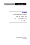
1
ECW-281B-945GSE Embedded System ECW-281B-945GSE Embedded System MODEL: ECW-281B-945GSE IEI Intel® Atom Fanless Embedded System RoHS Compliant, Dual GbE LAN, COM Ports, USB 2.0 User Manual Page i Rev. 1.01 17 March, 2009 ECW-281B-945GSE Embedded System Revision Date Version Changes 17 March, 2009 1.01 Changed model name 10 February, 2009 1.00 Initial release Page ii ECW-281B-945GSE Embedded System Copyright COPYRIGHT NOTICE The information in this document is subject to change without prior notice in order to improve reliability, design and function and does not represent a commitment on the part of the manufacturer. In no event will the manufacturer be liable for direct, indirect, special, incidental, or consequential damages arising out of the use or inability to use the product or documentation, even if advised of the possibility of such damages. This document contains proprietary information protected by copyright. All rights are reserved. No part of this manual may be reproduced by any mechanical, electronic, or other means in any form without prior written permission of the manufacturer. TRADEMARKS All registered trademarks and product names mentioned herein are used for identification purposes only and may be trademarks and/or registered trademarks of their respective owners. Page iii ECW-281B-945GSE Embedded System Packing List NOTE: If any of the components listed in the checklist below are missing, please do not proceed with the installation. Contact the IEI reseller or vendor you purchased the ECW-281B-945GSE from or contact an IEI sales representative directly. To contact an IEI sales representative, please send an email to [email protected]. The items listed below should all be included in the ECW-281B-945GSE package. 1 x ECW-281B-945GSE embedded system 2 x Mounting brackets 1 x Screw set 1 x Thermal pad for HDD 1 x Mini jumper set 1 x QIG 1 x Driver and manual CD 1 x 2 dbi wireless antenna (for wireless models only) 1 x Power cord (optional for WD models) 1 x Power Adaptor (optional for WD models) Page iv ECW-281B-945GSE Embedded System Table of Contents 1 INTRODUCTION..................................................................................................... 1 1.1 ECW-281B-945GSE EMBEDDED SYSTEM OVERVIEW............................................... 2 1.1.1 ECW-281B-945GSE Benefits ............................................................................. 2 1.1.2 ECW-281B-945GSE Features............................................................................ 2 1.2 ECW-281B-945GSE MODEL VARIATIONS ................................................................. 3 1.3 TECHNICAL SPECIFICATIONS ...................................................................................... 4 1.4 POWER MODULE SPECIFICATIONS .............................................................................. 6 1.4.1 Power Module Options ...................................................................................... 6 1.4.2 Power Module Specifications ............................................................................ 6 1.5 POWER ADAPTER ....................................................................................................... 7 2 MECHANICAL DESCRIPTION............................................................................ 9 2.1 ECW-281B-945GSE MECHANICAL OVERVIEW ....................................................... 10 2.2 PHYSICAL DIMENSIONS ............................................................................................ 10 2.2.1 ECW-281B-945GSE Dimensions ..................................................................... 10 2.2.2 Motherboard Dimensions .................................................................................11 2.2.3 Power Module Dimensions .............................................................................. 12 2.3 EXTERNAL OVERVIEW .............................................................................................. 13 2.3.1 Front Panel ...................................................................................................... 13 2.3.2 Rear Panel ....................................................................................................... 13 2.3.3 Bottom Surface................................................................................................. 14 2.4 INTERNAL OVERVIEW ............................................................................................... 15 3 SYSTEM COMPONENTS .................................................................................... 17 3.1 ECW-281B-945GSE EMBEDDED SYSTEM MOTHERBOARD..................................... 18 3.1.1 ECW-281B-945GSE Embedded System Motherboard..................................... 18 3.1.2 WAFER-945GSE Motherboard Overview........................................................ 18 3.1.3 CPU Support.................................................................................................... 19 3.2 PERIPHERAL INTERFACE CONNECTORS..................................................................... 19 3.2.1 Peripheral Interface Connectors ..................................................................... 19 3.3 INTERNAL PERIPHERAL CONNECTORS ...................................................................... 20 Page v ECW-281B-945GSE Embedded System 3.3.1 ATX Power Connector ..................................................................................... 20 3.3.2 ATX Power Supply Enable Connector ............................................................. 21 3.3.3 Audio Connector (10-pin) ................................................................................ 22 3.3.4 CompactFlash® Socket.................................................................................... 23 3.3.5 LED Connector ................................................................................................ 25 3.3.6 PCIe Mini Card Slot ........................................................................................ 26 3.3.7 Power Button Connector.................................................................................. 28 3.3.8 Reset Button Connector ................................................................................... 28 3.3.9 SATA Drive Connectors ................................................................................... 29 3.3.10 Serial Port Connector (COM3, COM4, COM5 and COM6)......................... 30 3.3.11 Serial Port Connector (COM 2)(RS-232, RS-422 or RS-485) ....................... 32 3.3.12 USB Connectors (Internal) ............................................................................ 33 3.4 EXTERNAL PERIPHERAL INTERFACE CONNECTOR PANEL ......................................... 34 3.4.1 LAN Connectors............................................................................................... 35 3.4.2 Serial Port Connector (COM1) ....................................................................... 36 3.4.3 USB Connectors............................................................................................... 37 3.4.4 VGA Connector ................................................................................................ 37 3.5 WAFER-945GSE MOTHERBOARD ON-BOARD JUMPERS ......................................... 39 3.5.1 CF Card Setup ................................................................................................. 40 3.5.2 Clear CMOS Jumper........................................................................................ 40 3.5.3 COM 2 Function Select Jumper....................................................................... 42 3.6 CONNECTOR MAPPINGS ........................................................................................... 43 3.6.1 Power Connector ............................................................................................. 43 3.6.2 ATX Mode Connector....................................................................................... 43 4 INSTALLATION .................................................................................................... 44 4.1 ANTI-STATIC PRECAUTIONS ...................................................................................... 45 4.2 INSTALLATION PROCEDURE ...................................................................................... 45 4.2.1 Installation Procedure Overview ..................................................................... 45 4.2.2 Unpacking ........................................................................................................ 46 4.2.3 Bottom Surface Removal.................................................................................. 48 4.2.4 Configure the Jumper Settings ......................................................................... 48 4.2.5 Hard Drive Installation.................................................................................... 49 4.2.6 Mounting the System with Mounting Brackets................................................. 51 4.2.7 Mounting the System with Wall Mount Kit....................................................... 52 Page vi ECW-281B-945GSE Embedded System 4.2.8 DIN Mounting .................................................................................................. 54 4.2.9 Wireless Antenna Installation (Wireless Models Only).................................... 56 4.2.10 Cable Connections ......................................................................................... 57 4.3 POWER-ON PROCEDURE ........................................................................................... 57 4.3.1 Installation Checklist ....................................................................................... 57 4.3.2 Terminal Block Pinouts .................................................................................... 58 4.3.3 Power-on Procedure ........................................................................................ 58 5 BIOS SCREENS...................................................................................................... 60 5.1 INTRODUCTION......................................................................................................... 61 5.1.1 Starting Setup................................................................................................... 61 5.1.2 Using Setup ...................................................................................................... 61 5.1.3 Getting Help..................................................................................................... 62 5.1.4 Unable to Reboot After Configuration Changes.............................................. 62 5.1.5 BIOS Menu Bar................................................................................................ 62 5.2 MAIN........................................................................................................................ 63 5.3 ADVANCED ............................................................................................................... 64 5.3.1 CPU Configuration.......................................................................................... 65 5.3.2 IDE Configuration ........................................................................................... 66 5.3.2.1 IDE Master, IDE Slave ............................................................................. 68 5.3.3 Super IO Configuration ................................................................................... 74 5.3.4 Hardware Health Configuration...................................................................... 78 5.3.5 Power Configuration........................................................................................ 82 5.3.5.1 ACPI configuration ................................................................................... 82 5.3.5.2 APM Configuration................................................................................... 83 5.3.6 Remote Configuration ...................................................................................... 86 5.3.7 USB Configuration........................................................................................... 90 5.4 PCI/PNP................................................................................................................... 92 5.5 BOOT........................................................................................................................ 95 5.5.1 Boot Settings Configuration............................................................................. 95 5.5.2 Boot Device Priority ........................................................................................ 98 5.6 SECURITY ................................................................................................................. 99 5.7 CHIPSET ................................................................................................................. 100 5.7.1 North Bridge Chipset Configuration ............................................................. 101 5.7.2 SouthBridge Configuration............................................................................ 104 Page vii ECW-281B-945GSE Embedded System 5.8 EXIT ....................................................................................................................... 105 6 SOFTWARE DRIVERS ....................................................................................... 107 6.1 AVAILABLE SOFTWARE DRIVERS ............................................................................ 108 6.2 STARTING THE DRIVER PROGRAM .......................................................................... 108 6.3 CHIPSET DRIVER INSTALLATION ............................................................................. 109 6.4 VGA DRIVER INSTALLATION ...................................................................................114 6.5 LAN DRIVER INSTALLATION ...................................................................................119 6.6 AUDIO DRIVER INSTALLATION ............................................................................... 122 7 TROUBLESHOOTING AND MAINTENANCE .............................................. 127 7.1 ECW-281B-945GSE SYSTEM MAINTENANCE OVERVIEW ..................................... 128 7.2 SYSTEM TROUBLESHOOTING .................................................................................. 128 7.2.1 The System Doesn’t Turn On .......................................................................... 128 7.2.2 The System Doesn’t Boot Up.......................................................................... 129 7.2.3 More Troubleshooting .................................................................................... 130 7.3 COMPONENT REPLACEMENT PROCEDURE .............................................................. 130 7.3.1 SO-DIMM Replacement................................................................................. 131 A SAFETY PRECAUTIONS................................................................................... 133 A.1 SAFETY PRECAUTIONS .......................................................................................... 134 A.1.1 General Safety Precautions ........................................................................... 134 A.1.2 Anti-static Precautions .................................................................................. 135 A.2 MAINTENANCE AND CLEANING PRECAUTIONS ...................................................... 135 A.2.1 Maintenance and Cleaning............................................................................ 135 A.2.2 Cleaning Tools ............................................................................................... 136 B IEI EMBEDDED SYSTEM SERIES .................................................................. 137 B.1 IEI EMBEDDED SYSTEM SERIES............................................................................. 138 B.1.1 Overview........................................................................................................ 138 B.1.2 IEI Embedded System Series ......................................................................... 138 B.1.3 IEI Embedded System Series Variations........................................................ 139 B.2 EMBEDDED SYSTEM SOLUTIONS ........................................................................... 139 B.2.1 AMD® Geode® LX800 500MHz Solutions..................................................... 139 B.2.2 AMD® Geode® GX466 333MHz Solutions.................................................... 140 B.2.3 VIA® LUKE® 1GHz Solutions ....................................................................... 140 Page viii ECW-281B-945GSE Embedded System B.2.4 VIA® MARK® 800MHz Solutions .................................................................. 141 B.2.5 Intel® Celeron® M 1 GHz Solutions .............................................................. 141 B.2.6 Intel® Celeron® M 1.5GHz Solutions ............................................................ 142 B.2.7 Intel® Pentium® M 1.6GHz Solutions............................................................ 143 B.2.8 Intel® Socket 479 Pentium®/Celeron® M 2GHz Solutions ............................ 143 B.2.9 LGA 775 Intel® Pentium® 4/ Pentium® D Solutions ..................................... 144 B.2.10 Intel® Socket 479 Core Duo/Solo Solutions ................................................ 145 C BIOS MENU OPTIONS....................................................................................... 146 C.1 BIOS CONFIGURATION OPTIONS ........................................................................... 147 D WATCHDOG TIMER .......................................................................................... 150 Page ix ECW-281B-945GSE Embedded System List of Figures Figure 1-1: ECW-281B-945GSE Series Embedded System.......................................2 Figure 1-2: Power Adapter ...........................................................................................7 Figure 2-1: ECW-281B-945GSE Dimensions (mm) ..................................................11 Figure 2-2: WAFER SBC Dimensions (mm)..............................................................12 Figure 2-3: Power Module Dimensions (mm) ...........................................................12 Figure 2-4: ECW-281B-945GSE Front Panel.............................................................13 Figure 2-5: ECW-281B-945GSE Rear Panel ..............................................................14 Figure 2-6: Bottom Surface ........................................................................................15 Figure 2-7: Internal Overview.....................................................................................16 Figure 3-1: WAFER-945GSE Jumper and Connector Locations ............................18 Figure 3-2: ATX Power Connector Location.............................................................21 Figure 3-3: ATX Power Supply Enable Connector Location...................................22 Figure 3-4: Audio Connector Pinouts (10-pin) .........................................................23 Figure 3-5: CF Card Socket Location ........................................................................24 Figure 3-6: LED Connector Locations.......................................................................25 Figure 3-7: PCIe Mini Card Slot Location..................................................................26 Figure 3-8: Power Button Connector Location ........................................................28 Figure 3-9: Reset Button Connector Locations .......................................................29 Figure 3-10: SATA Drive Connector Locations........................................................30 Figure 3-11: COM3 to COM6 Connector Pinout Locations .....................................31 Figure 3-12: RS-232/422/485 Serial Port Connector Location ................................33 Figure 3-13: USB Connector Pinout Locations........................................................34 Figure 3-14: ECW-281B-945GSE External Peripheral Interface Connector...........35 Figure 3-15: RJ-45 Ethernet Connector ....................................................................36 Figure 3-16: COM1 Pinout Locations ........................................................................37 Figure 3-17: VGA Connector ......................................................................................38 Figure 3-18: Jumpers ..................................................................................................39 Figure 3-19: CF Card Setup Jumper Location..........................................................40 Page x ECW-281B-945GSE Embedded System Figure 3-20: Clear CMOS Jumper ..............................................................................41 Figure 3-21: COM 2 Function Select Jumper Location ...........................................42 Figure 4-1: Bottom Surface Retention Screws.........................................................48 Figure 4-2: Hard Drive Bracket ..................................................................................49 Figure 4-3:HDD Bracket Retention Screws ..............................................................49 Figure 4-4: HDD Retention Screws............................................................................50 Figure 4-5: HDD Thermal Pad ....................................................................................51 Figure 4-6: Mounting Bracket Retention Screws .....................................................52 Figure 4-7: Wall-mounting Bracket............................................................................53 Figure 4-8: Mount the Embedded System ................................................................54 Figure 4-9: DIN Rail Mounting Bracket......................................................................55 Figure 4-10: Screw Locations ....................................................................................55 Figure 4-11: Mounting the DIN RAIL..........................................................................56 Figure 4-12: Secure the Assembly to the DIN Rail...................................................56 Figure 4-13: Wireless Antenna Installation ..............................................................57 Figure 4-14: Terminal Block Pinouts.........................................................................58 Figure 4-15: Power Button .........................................................................................59 Figure 6-1: Drivers.................................................................................................... 109 Figure 6-2: Chipset Driver Screen .......................................................................... 110 Figure 6-3: Chipset Driver Welcome Screen ......................................................... 110 Figure 6-4: Chipset Driver License Agreement..................................................... 111 Figure 6-5: Chipset Driver Read Me File ................................................................ 112 Figure 6-6: Chipset Driver Setup Operations ........................................................ 113 Figure 6-7: Chipset Driver Installation Finish Screen .......................................... 114 Figure 6-8: VGA Driver Read Me File...................................................................... 115 Figure 6-9: VGA Driver Setup Files Extracted....................................................... 115 Figure 6-10: VGA Driver Welcome Screen............................................................. 116 Figure 6-11: VGA Driver License Agreement ........................................................ 117 Figure 6-12: VGA Driver Read Me File.................................................................... 117 Figure 6-13: VGA Driver Setup Operations ........................................................... 118 Figure 6-14: VGA Driver Installation Finish Screen.............................................. 119 Figure 6-15: LAN Driver Welcome Screen ............................................................. 120 Page xi ECW-281B-945GSE Embedded System Figure 6-16: LAN Driver Welcome Screen ............................................................. 120 Figure 6-17: LAN Driver Installation ....................................................................... 121 Figure 6-18: LAN Driver Installation Complete ..................................................... 122 Figure 6-19: Audio Driver Options.......................................................................... 123 Figure 6-20: AC’97 Driver Installation File Extraction .......................................... 123 Figure 6-21: AC’97 Driver Installation Welcome Screen ...................................... 124 Figure 6-22: AC’97 Driver Installation Verification............................................. 125 Figure 6-23: AC’97 Driver Installation .................................................................... 125 Figure 6-24: AC’97 Driver Installation Complete................................................... 126 Figure 7-1: SO-DIMM Cover Plate ........................................................................... 131 Figure 7-2: SO-DIMM Installation............................................................................ 132 Page xii ECW-281B-945GSE Embedded System List of Tables Table 1-1: Model Variations..........................................................................................3 Table 1-2: Technical Specifications ............................................................................5 Table 1-3: ECW-281B-945GSE Power Module Options .............................................6 Table 1-4: DC-to-DC Power Module Specifications ...................................................7 Table 1-5: Power Adapter Specifications....................................................................8 Table 3-1: Peripheral Interface Connectors..............................................................20 Table 3-2: ATX Power Connector Pinouts ................................................................21 Table 3-3: ATX Power Supply Enable Connector Pinouts ......................................22 Table 3-4: Audio Connector Pinouts (10-pin)...........................................................23 Table 3-5: CF Card Socket Pinouts ...........................................................................25 Table 3-6: LED Connector Pinouts ............................................................................26 Table 3-7: PCIe Mini Card Slot Pinouts .....................................................................27 Table 3-8: Power Button Connector Pinouts............................................................28 Table 3-9: Reset Button Connector Pinouts.............................................................29 Table 3-10: SATA Drive Connector Pinouts .............................................................30 Table 3-11: COM3 to COM6 Connector Pinouts.......................................................32 Table 3-12: RS-232/RS-485 Serial Port Connector Pinouts.....................................33 Table 3-13: USB Port Connector Pinouts .................................................................34 Table 3-14: LAN Pinouts.............................................................................................35 Table 3-15: RJ-45 Ethernet Connector LEDs............................................................36 Table 3-16: RS-232 Serial Port (COM 1) Pinouts ......................................................36 Table 3-17: USB Port Pinouts ....................................................................................37 Table 3-18: VGA Connector Pinouts .........................................................................38 Table 3-19: Jumpers....................................................................................................39 Table 3-20: CF Card Setup Jumper Settings ............................................................40 Table 3-21: Clear CMOS Jumper Settings ................................................................41 Table 3-22: COM 2 Function Select Jumper Settings..............................................42 Table 3-23: Motherboard Power Connector Mapping..............................................43 Page xiii ECW-281B-945GSE Embedded System Table 3-24: Motherboard Power Connector Mapping..............................................43 Table 4-1: Package List Contents..............................................................................47 Table 5-1: BIOS Navigation Keys...............................................................................62 Page xiv ECW-281B-945GSE Embedded System List of BIOS Menus Menu 1: Main 63 Menu 2: Advanced.......................................................................................................65 Menu 3: CPU Configuration .......................................................................................65 Menu 4: IDE Configuration .........................................................................................66 Menu 5: IDE Master and IDE Slave Configuration ...................................................68 Menu 6: Super IO Configuration ................................................................................74 Menu 7: Hardware Health Configuration ..................................................................78 Menu 8: Power Configuration ....................................................................................82 Menu 9: ACPI Configuration ......................................................................................83 Menu 10:Advanced Power Management Configuration..........................................84 Menu 11: Remote Access Configuration [Advanced] .............................................87 Menu 12: USB Configuration .....................................................................................91 Menu 13: PCI/PnP Configuration ...............................................................................93 Menu 14: Boot..............................................................................................................95 Menu 15: Boot Settings Configuration......................................................................96 Menu 16: Boot Device Priority Settings ....................................................................98 Menu 17: Security........................................................................................................99 Menu 18: Chipset...................................................................................................... 100 Menu 19:North Bridge Chipset Configuration....................................................... 101 Menu 20:SouthBridge Chipset Configuration ....................................................... 104 Menu 21:Exit ............................................................................................................. 105 Page xv ECW-281B Embedded System Chapter 1 1 Introduction Page 1 ECW-281B Embedded System 1.1 ECW-281B-945GSE Embedded System Overview Figure 1-1: ECW-281B-945GSE Series Embedded System There are four WAFER-945GSE Intel® Atom™ based embedded solutions in the ECW-281B-945GSE series. All fanless motherboards have been optimized for multimedia applications that require minimum installation space. The WAFER-945GSE motherboard supports a full range of functions for an AT/ATX-compatible industrial computer. ECW-281B-945GSE embedded subsystems are all capable of supporting one 2.5” SATA hard disk drive. The ECW-281B-945GSE-W models also have a built-in 802.11 b/g wireless module. 1.1.1 ECW-281B-945GSE Benefits The ECW-281B-945GSE embedded system has the following benefits: Easy installation saves installation time Complete integration saves solution development time and cost Secure storage with one SATA hard drive supported Compact size saves space Powerful preinstalled Intel® Atom™ N270 CPU and motherboard ensures rigorous processing needs can be met 1.1.2 ECW-281B-945GSE Features The ECW-281B-945GSE has the following features Page 2 ECW-281B Embedded System RoHS compliant design Fanless system Built-in DC-to-DC power converter 1.6 GHz Intel® Atom™ N270 CPU supported Dual GbE LAN for high speed network applications One SATA hard drive supported Wall mount and DIN mount supported. 1.2 ECW-281B-945GSE Model Variations There are four models in the ECW-281B-945GSE embedded system series. The ECW-281B-945GSE series supports 12V DC input and the ECW-281BWD-945GSE series supports 9V~36V DC input. The four models are listed in Table 1-1 below. ECW-281B -945GSE-R10/1GB CPU Intel® Atom™ N270 Memory 1 GB DDR Power Wireless 12V DC input No (55 W adaptor) -945GSE-W-R10/1GB Intel® Atom™ N270 1 GB DDR 12V DC input Yes (55 W adaptor) ECW-281BWD -945GSE-R10/1GB CPU Intel® Atom™ N270 Memory 1 GB DDR Power 9V~36V DC Wireless No input -945GSE-W-R10/1GB Intel® Atom™ N270 1 GB DDR 9V~36V DC Yes input Table 1-1: Model Variations Page 3 ECW-281B Embedded System 1.3 Technical Specifications The specifications for the Intel based embedded systems are listed below. ECW-281B-945GSE CPU Preinstalled 1.6 GHz Intel® Atom™ Processor N270 with a 533 MHz FSB System Chipset Intel® 945GSE + ICH7-M System Memory Preinstalled 1.0 GB DDR2 SDRAM SO-DIMM (system max. 2 GB) Ethernet Dual Realtek RTL8111CP GbE controllers Buit-in 802.11 b/g wireless module for the wireless models Display CRT integrated in Intel® 945GSE USB Four USB 2.0 ports Serial Port Five RS-232 One RS-232/422/485 (selectable) Audio One audio out Storage One 2.5” SATA hard drive supported One internal CF card slot Chassis Construction Aluminum Alloy Power Supply Internal DC-to-DC power converter, input voltage: 12V DC or 9V – 36V (WD series models) External power adapter, input voltage: 90V AC ~ 264V AC @ 47Hz ~ 63Hz, 55 W Power Consumption 19 W Operating Shock Half-sine wave shock 3G; 11ms; 3 shocks per axis Page 4 ECW-281B Embedded System Operating Vibration MIL-STD-810F 514.5C-1 (HDD) MIL-STD-810F 514.5C-2 (CF) Operating temperature -10ºC ~ 50ºC with HDD -10ºC ~ 60ºC with CF card Color Black Mounting DIN mount VESA MIS-D 100 wall mount Weight (Net/Gross) 2.1 kg/3.9 kg Dimensions (D x W x H) 132 mm x 229 mm x 64 mm EMC FCC Class A, CE Table 1-2: Technical Specifications Page 5 ECW-281B Embedded System 1.4 Power Module Specifications 1.4.1 Power Module Options The ECW-281B-945GSE embedded system supports either a 12V DC input or a 9V~36V DC input. The input support depends on the power module installed in the system. The two power modules are listed in Table 1-3: Embedded System Power Module DC Input ECW-281B-945GSE Series IDD-12250A 12V DC input ECW-281BWD-945GSE Series IDD-936260A 9V~36V DC input Table 1-3: ECW-281B-945GSE Power Module Options 1.4.2 Power Module Specifications The specifications for the IDD-12250A and IDD-936260A are shown in Table 1-4. Model Name: IDD-12250A IDD-936260A 12VDC 9VDC~36VDC 12V 5A (pass thru.) 3A (Max.) 5V 10A (Max.) 10A (Max.) 5VSB 0.5A (Max.) 0.5A (Max.) 50W+60W (12V pass thru.) 60W Input Output: Max. Total Output: Performance Characteristics: Page 6 Noise & Ripple: < 240mV < 240mV Line Regulation: < 20mV < 20mV ECW-281B Embedded System Load Regulation <60mV <60mV Efficiency: Up to 90% Up to 90% Dimensions: 40mm x 100mm 40mm x 100mm Weight: 46g 58g Operating Temperature: -40°C~85°C -40°C~85°C Table 1-4: DC-to-DC Power Module Specifications 1.5 Power Adapter The ECW-281B-945GSE series models are shipped with a 55 W power adapter. Figure 1-2: Power Adapter The specifications for the adapter are listed in Table 1-5: Output Nominal 12.0V Regulation 11.52V – 12.48V Ripple/Noise 120mV Min. 0A Max. 4.58A Page 7 ECW-281B Embedded System Output can be shorted without damage and Short Circuit Protection Time Input auto-recovery Over-Voltage Upper Trip Limit: Hold Up 10ms Min. 90V Nominal 115V ~ 230V Max. 264V Frequency 47Hz ~ 63Hz Inrush Current 80A Max. (cold start at 25ºC) Steady Current 1.3Arms Max. Efficiency 80% (typical) 15V+/-1.5V Operating 0ºC ~ 40ºC Storage -25ºC ~ 65ºC Operating (non-condensing) 0% ~ 95% Storage (non-condensing) 0% ~ 95% Temperature Relative Humidity Operating: 1G, 5Hz~500Hz, random vibration, Environment 30mins/axis, 3 direction Vibration Storage: 2G, 5Hz~500Hz, random vibration, 30mins/axis, 3 direction Operating: 10G, 11ms, Half-sine wave Shock Storage: 20G, 11ms, Half-sine wave MTBF 100,000 hours of continuous operation at 25ºC Leakage Current 0.5mA max @264V Reliability Table 1-5: Power Adapter Specifications Page 8 ECW-281B Embedded System Chapter 2 2 Mechanical Description Page 9 ECW-281B Embedded System 2.1 ECW-281B-945GSE Mechanical Overview The ECW-281B-945GSE RoHS compliant, Intel® Atom™ fanless embedded system features industrial grade components that offer longer operating life, high shock/vibration resistance and endurance over a wide temperature range. The ECW-281B-945GSE combines these features in an aluminum enclosure designed for space critical applications that require low power consumption. Featuring two LAN, four USB, six serial communication ports, as well as audio, and VGA, the ECW-281B-945GSE offers system integrators and developers the best selection of robust and high performance computing system platforms. An internal bracket supports one 2.5” SATA hard drives. 2.2 Physical Dimensions The physical dimensions of the ECW-281B-945GSE embedded systems are listed below. 2.2.1 ECW-281B-945GSE Dimensions The dimensions of the ECW-281B-945GSE are listed below and shown in Figure 2-1. Height: 64.00 mm Width: 229.00 mm Length: 132.00 mm Page 10 ECW-281B Embedded System Figure 2-1: ECW-281B-945GSE Dimensions (mm) 2.2.2 Motherboard Dimensions The WAFER series dimension are listed below and shown in Figure 2-2. Length: 145.00 mm Width: 102.00 mm Page 11 ECW-281B Embedded System Figure 2-2: WAFER SBC Dimensions (mm) 2.2.3 Power Module Dimensions The power module dimensions are listed below and shown in Figure 2-3. Length: 100.00 mm Width: 40.00 mm Figure 2-3: Power Module Dimensions (mm) Page 12 ECW-281B Embedded System 2.3 External Overview 2.3.1 Front Panel The ECW-281B-945GSE front panel contains: 2 x USB port connectors 1 x HDD LED indicator 1 x Power button An overview of the front panel is shown in Figure 2-4 below. Figure 2-4: ECW-281B-945GSE Front Panel 2.3.2 Rear Panel The rear panel of the ECW-281B-945GSE provides access to the following external I/O connectors. 2 x USB port connectors 2 x RJ-45 Ethernet connector 1 x VGA connector 1 x RS-232/422/485 serial port 5 x RS-232 serial ports 1 x Speaker out 1 x 3-pin power terminal block 1 x 12V DC power jack 1 x Wireless antenna connector (for wireless models only) Page 13 ECW-281B Embedded System An overview of the rear panel is shown in Figure 2-5. Figure 2-5: ECW-281B-945GSE Rear Panel 2.3.3 Bottom Surface WARNING: Never remove the bottom access panel from the chassis while power is still being fed into the system. Before removing the bottom access panel, make sure the system has been turned off and all power connectors unplugged. The bottom surface of the ECW-281B-945GSE contains the retention screw holes for the VESA MIS-D 100 wall-mount kit, two-side mounting brackets and DIN mount bracket. Page 14 ECW-281B Embedded System Figure 2-6: Bottom Surface 2.4 Internal Overview The ECW-281B-945GSE internal components are listed below: 1 x IEI WAFER motherboard (preinstalled) 1 x IEI power module (preinstalled) 1 x SO-DIMM module (preinstalled) 1 x Hard drive bracket and SATA cable support one SATA hard disk All the components are accessed by removing the bottom surface. Page 15 ECW-281B Embedded System Figure 2-7: Internal Overview Page 16 ECW-281B Embedded System Chapter 3 3 System Components Page 17 ECW-281B Embedded System 3.1 ECW-281B-945GSE Embedded System Motherboard 3.1.1 ECW-281B-945GSE Embedded System Motherboard NOTE: The jumpers and connectors shown in the section below are those jumpers and connectors that are relevant to the configuration and installation of the embedded system. For a complete list of jumpers and connectors on the WAFER-945GSE motherboard, please refer to the WAFER-945GSE user manual. The ECW-281B-945GSE models have a WAFER-945GSE motherboard installed in the system. The following sections describe the relevant connectors and jumpers on the motherboard. 3.1.2 WAFER-945GSE Motherboard Overview The locations of the WAFER-945GSE jumpers and connectors used on the ECW-281B-945GSE are shown in Figure 3-1 below. Figure 3-1: WAFER-945GSE Jumper and Connector Locations Page 18 ECW-281B Embedded System 3.1.3 CPU Support NOTE: The ECW-281B-945GSE series has a preinstalled Intel® Atom™ 1.6 GHz CPU on-board. If the CPU fails, the motherboard has to be replaced. Please contact the IEI reseller or vendor you purchased the ECW-281B-945GSE from or contact an IEI sales representative directly. To contact an IEI sales representative, please send an email to [email protected]. The ECW-281B-945GSE comes with an embedded 45 nm 1.60 GHz Intel® Atom™ processor N270. The processor supports a 533 MHz FSB and has a 1.6 GHz 512 KB L2 cache. The low power processor has a maximum power of 2.5 W. 3.2 Peripheral Interface Connectors Section 3.2.1 lists all the peripheral interface connectors seen in Section 3.1.2. 3.2.1 Peripheral Interface Connectors Table 3-1 shows a list of the peripheral interface connectors on the WAFER-945GSE that are used for the ECW-281B-945GSE. Detailed descriptions of these connectors can be found in Section 3.3. Connector Type Label Audio connector 10-pin header AUDIO1 ATX enable connector 3-pin wafer ATXCTL1 ATX power connector 4-pin ATX ATXPWR1 CompactFlash® socket 50-pin CF socket CF1 LED connector 6-pin header LED_C1 Page 19 ECW-281B Embedded System PCIe Mini Card slot PCIe Mini Slot CN4 Power Button 2-pin wafer PWRBTN1 Reset button connector 2-pin header RESET1 Serial ATA (SATA) drive connectors 7-pin SATA SATA1 RS-232 serial port connector (COM3 – COM6) 40-pin header COM RS-232/422/485 serial port connector 14-pin header COM2 USB 2.0 connector 8-pin header USB01 Table 3-1: Peripheral Interface Connectors 3.3 Internal Peripheral Connectors Internal peripheral connectors are found on the motherboard and are only accessible when the motherboard is outside of the chassis. This section has complete descriptions of the internal, peripheral connectors on the WAFER-945GSE that are used for the ECW-281B-945GSE. 3.3.1 ATX Power Connector CN Label: ATXPWR1 CN Type: 4-pin AT power connector (1x4) CN Location: See Figure 3-2 CN Pinouts: See Table 3-2 The 4-pin ATX power connector is connected to a DC-DC power module. Page 20 ECW-281B Embedded System Figure 3-2: ATX Power Connector Location PIN NO. DESCRIPTION 1 +12V 2 GND 3 GND 4 +5V Table 3-2: ATX Power Connector Pinouts 3.3.2 ATX Power Supply Enable Connector CN Label: ATXCTL1 CN Type: 3-pin wafer (1x3) CN Location: See Figure 3-3 CN Pinouts: See Table 3-3 The ATX power supply enable connector is connected to the ATX mode connector on the power module to enable the ECW-281B-945GSE to be connected to an ATX power supply. Page 21 ECW-281B Embedded System Figure 3-3: ATX Power Supply Enable Connector Location PIN NO. DESCRIPTION 1 +5V Standby 2 GND 3 PS-ON Table 3-3: ATX Power Supply Enable Connector Pinouts 3.3.3 Audio Connector (10-pin) CN Label: AUDIO1 CN Type: 10-pin header CN Location: See Figure 3-4 CN Pinouts: See Table 3-4 The 10-pin audio connector is interfaced to an audio line-out connector and provides output of audio signals from the system. Page 22 ECW-281B Embedded System Figure 3-4: Audio Connector Pinouts (10-pin) PIN NO. DESCRIPTION PIN NO. DESCRIPTION 1 Line out R 2 Line in R 3 GND 4 GND 5 Line out L 6 Line in L 7 GND 8 GND 9 MIC in 10 Mic in Table 3-4: Audio Connector Pinouts (10-pin) 3.3.4 CompactFlash® Socket CN Label: CF1 CN Type: 50-pin header (2x25) CN Location: See Figure 3-5 CN Pinouts: See Table 3-5 A CF Type I or Type II memory card is inserted to the CF socket on the solder side of the ECW-281B-945GSE. Page 23 ECW-281B Embedded System Figure 3-5: CF Card Socket Location PIN NO. DESCRIPTION PIN NO. DESCRIPTION 1 GROUND 26 VCC-IN CHECK1 2 DATA 3 27 DATA 11 3 DATA 4 28 DATA 12 4 DATA 5 29 DATA 13 5 DATA 6 30 DATA 14 6 DATA 7 31 DATA 15 7 HDC_CS0# 32 HDC_CS1 8 GROUND 33 N/C 9 GROUND 34 IOR# 10 GROUND 35 IOW# 11 GROUND 36 VCC_COM 12 GROUND 37 IRQ14 13 VCC_COM 38 VCC_COM 14 GROUND 39 CSEL 15 GROUND 40 N/C 16 GROUND 41 HDD_RESET Page 24 ECW-281B Embedded System PIN NO. DESCRIPTION PIN NO. DESCRIPTION 17 GROUND 42 IORDY 18 SA2 43 SDREQ 19 SA1 44 SDACK# 20 SA0 45 HDD_ACTIVE# 21 DATA 0 46 66DET 22 DATA 1 47 DATA 8 23 DATA 2 48 DATA 9 24 N/C 49 DATA 10 25 VCC-IN CHECK2 50 GROUND Table 3-5: CF Card Socket Pinouts 3.3.5 LED Connector CN Label: LED_C1 CN Type: 6-pin wafer (1x6) CN Location: See Figure 3-6 CN Pinouts: See Table 3-6 The LED connector connects to an HDD indicator LED and a power LED on the system chassis to inform the user about HDD activity and the power on/off status of the system. Figure 3-6: LED Connector Locations Page 25 ECW-281B Embedded System PIN NO. DESCRIPTION 1 +5V 2 GND 3 Power LED+ 4 Power LED- 5 HDD LED+ 6 HDD LED- Table 3-6: LED Connector Pinouts 3.3.6 PCIe Mini Card Slot CN Label: CN4 CN Type: 52-pin Mini PCIe Card Slot CN Location: See Figure 3-7 CN Pinouts: See Table 3-7 6 The PCIe mini card slot enables a PCIe mini card expansion module to be connected to the board. Cards supported include among others wireless LAN (WLAN) cards. Figure 3-7: PCIe Mini Card Slot Location Page 26 ECW-281B Embedded System PIN NO. DESCRIPTION PIN NO. DESCRIPTION 1 PCIE_WAKE# 2 VCC3 3 N/C 4 GND 5 N/C 6 1.5V 7 CLKREQ# 8 LFRAME# 9 GND 10 LAD3 11 CLK- 12 LAD2 13 CLK+ 14 LAD1 15 GND 16 LAD0 17 PCIRST# 18 GND 19 LPC 20 VCC3 21 GND 22 PCIRST# 23 PERN2 24 3VDual 25 PERP2 26 GND 27 GND 28 1.5V 29 GND 30 SMBCLK 31 PETN2 32 SMBDATA 33 PETP2 34 GND 35 GND 36 USBD- 37 N/C 38 USBD+ 39 N/C 40 GND 41 N/C 42 N/C 43 N/C 44 RF_LINK# 45 N/C 46 BLUELED# 47 N/C 48 1.5V 49 N/C 50 GND 51 N/C 52 VCC3 Table 3-7: PCIe Mini Card Slot Pinouts Page 27 ECW-281B Embedded System 3.3.7 Power Button Connector CN Label: PWRBTN1 CN Type: 2-pin wafer (1x2) CN Location: See Figure 3-8 CN Pinouts: See Table 3-8 The power button connector is connected to a power switch on the system chassis to enable users to turn the system on and off. Figure 3-8: Power Button Connector Location PIN NO. DESCRIPTION 1 Power Switch 2 GND Table 3-8: Power Button Connector Pinouts 3.3.8 Reset Button Connector CN Label: RESET1 CN Type: 2-pin wafer (1x2) CN Location: See Figure 3-9 CN Pinouts: See Table 3-9 Page 28 ECW-281B Embedded System The reset button connector is connected to a reset switch on the system chassis to enable users to reboot the system when the system is turned on. Figure 3-9: Reset Button Connector Locations PIN NO. DESCRIPTION 1 Reset Switch 2 GND Table 3-9: Reset Button Connector Pinouts 3.3.9 SATA Drive Connectors CN Label: SATA1, SATA2 CN Type: 7-pin SATA drive connectors CN Location: See Figure 3-10 CN Pinouts: See Table 3-10 6 6 The SATA drive connectors are each connected to a first generation SATA drive. First generation SATA drives transfer data at speeds as high as 150Mb/s. The SATA drives can be configured in a RAID configuration. Page 29 ECW-281B Embedded System Figure 3-10: SATA Drive Connector Locations PIN NO. DESCRIPTION 1 GND 2 TX+ 3 TX- 4 GND 5 RX- 6 RX+ 7 GND Table 3-10: SATA Drive Connector Pinouts 3.3.10 Serial Port Connector (COM3, COM4, COM5 and COM6) CN Label: COM CN Type: 40-pin header (2x20) CN Location: See Figure 3-11 CN Pinouts: See Table 3-11 The 40-pin serial port connector contains the following four serial ports: COM3, COM4, COM5 and COM6. All these serial ports are RS-232 serial communications channels. The serial port locations are specified below. Page 30 ECW-281B Embedded System COM3 is located on pin 1 to pin 10 COM4 is located on pin 11 to pin 20 COM5 is located on pin 21 to pin 30 COM6 is located on pin 31 to pin 40 Figure 3-11: COM3 to COM6 Connector Pinout Locations PIN NO. DESCRIPTION PIN NO. DESCRIPTION 1 DATA CARRIER DETECT (DCD3) 2 DATA SET READY (DSR3) 3 RECEIVE DATA (RXD3) 4 REQUEST TO SEND (RTS3) 5 TRANSMIT DATA (TXD3) 6 CLEAR TO SEND (CTS3) 7 DATA TERMINAL READY (DTR3) 8 RING INDICATOR (RI3) 9 GND 10 GND 11 DATA CARRIER DETECT (DCD4) 12 DATA SET READY (DSR4) 13 RECEIVE DATA (RXD4) 14 REQUEST TO SEND (RTS4) 15 TRANSMIT DATA (TXD4) 16 CLEAR TO SEND (CTS4) 17 DATA TERMINAL READY (DTR4) 18 RING INDICATOR (RI4) 19 GND 20 GND 21 DATA CARRIER DETECT (DCD5) 22 DATA SET READY (DSR5) 23 RECEIVE DATA (RXD5) 24 REQUEST TO SEND (RTS5) Page 31 ECW-281B Embedded System PIN NO. DESCRIPTION PIN NO. DESCRIPTION 25 TRANSMIT DATA (TXD5) 26 CLEAR TO SEND (CTS5) 27 DATA TERMINAL READY (DTR5) 28 RING INDICATOR (RI5) 29 GND 30 GND 31 DATA CARRIER DETECT (DCD6 32 DATA SET READY (DSR6) 33 RECEIVE DATA (RXD6) 34 REQUEST TO SEND (RTS6) 35 TRANSMIT DATA (TXD6 36 CLEAR TO SEND (CTS6) 37 DATA TERMINAL READY (DTR6 38 RING INDICATOR (RI6) 39 GND 40 GND Table 3-11: COM3 to COM6 Connector Pinouts 3.3.11 Serial Port Connector (COM 2)(RS-232, RS-422 or RS-485) CN Label: COM2 CN Type: 14-pin header (2x7) CN Location: See Figure 3-12 CN Pinouts: See Table 3-12 The 14-pin serial port connector connects to the COM2 serial communications channels. COM2 is a multi function channel. In default mode COM2 is an RS-232 serial communication channel but, with the COM2 function select jumper, can be configured as either an RS-422 or RS-485 serial communications channel. Page 32 ECW-281B Embedded System Figure 3-12: RS-232/422/485 Serial Port Connector Location PIN NO. DESCRIPTION PIN NO. DESCRIPTION 1 NDCD 2 NDSR2 3 NRX 4 NRTS2 5 NTX 6 NCTS2 7 NDTR 8 NRI2 9 GND 10 GND 11 TXD485+ 12 TXD485- 13 RXD485+ 14 RXD485- Table 3-12: RS-232/RS-485 Serial Port Connector Pinouts 3.3.12 USB Connectors (Internal) CN Label: USB01 and USB23 CN Type: 8-pin header (2x4) CN Location: See Figure 3-13 CN Pinouts: See Table 3-13 6 6 The 2x4 USB pin connectors each provide connectivity to two USB 1.1 or two USB 2.0 ports. Each USB connector can support two USB devices. Additional external USB ports are found on the rear panel. The USB ports are used for I/O bus expansion. Page 33 ECW-281B Embedded System Figure 3-13: USB Connector Pinout Locations PIN NO. DESCRIPTION PIN NO. DESCRIPTION 1 VCC 2 GND 3 DATA- 4 DATA+ 5 DATA+ 6 DATA- 7 GND 8 VCC Table 3-13: USB Port Connector Pinouts 3.4 External Peripheral Interface Connector Panel Figure 3-14 shows the ECW-281B-945GSE external peripheral interface connector (EPIC) 6 panel. The ECW-281B-945GSE EPIC panel consists of the following: 2 x RJ-45 LAN connectors 1 x Serial port connectors 2 x USB connectors 1 x VGA connector Page 34 ECW-281B Embedded System Figure 3-14: ECW-281B-945GSE External Peripheral Interface Connector 3.4.1 LAN Connectors CN Label: LAN1 and LAN2 CN Type: RJ-45 CN Location: See Figure 3-14 CN Pinouts: See Table 3-14 6 6 The ECW-281B-945GSE is equipped with two built-in RJ-45 Ethernet controllers. The controllers can connect to the LAN through two RJ-45 LAN connectors. There are two LEDs on the connector indicating the status of LAN. The pin assignments are listed in the following table: PIN DESCRIPTION PIN DESCRIPTION 1 MDIA3- 5 MDIA1+ 2 MDIA3+ 6 MDIA2+ 3 MDIA2- 7 MDIA0- 4 MDIA1- 8 MDIA0+ Table 3-14: LAN Pinouts Page 35 ECW-281B Embedded System Figure 3-15: RJ-45 Ethernet Connector The RJ-45 Ethernet connector has two status LEDs, one green and one yellow. The green LED indicates activity on the port and the yellow LED indicates the port is linked. See Table 3-15. 6 DESCRIPTION STATUS GREEN STATUS Activity DESCRIPTION YELLOW Linked Table 3-15: RJ-45 Ethernet Connector LEDs 3.4.2 Serial Port Connector (COM1) CN Label: COM1 CN Type: DB-9 connectors CN Location: See Figure 3-14 CN Pinouts: See Table 3-16 and Figure 3-16 6 6 6 The 9-pin DB-9 serial port connectors are connected to RS-232 serial communications devices. PIN NO. DESCRIPTION PIN NO. DESCRIPTION 1 DCD 6 DSR 2 RX 7 RTS 3 TX 8 CTS 4 DTR 9 RI 5 GND Table 3-16: RS-232 Serial Port (COM 1) Pinouts Page 36 ECW-281B Embedded System Figure 3-16: COM1 Pinout Locations 3.4.3 USB Connectors CN Label: USB CN Type: Dual USB port CN Location: See Figure 3-14 CN Pinouts: See Table 3-17 6 6 The ECW-281B-945GSE has two external USB 2.0 ports. The ports connect to both USB 2.0 and USB 1.1 devices. PIN NO. DESCRIPTION PIN NO. DESCRIPTION 1 VCC 5 VCC 2 DATA- 6 DATA- 3 DATA+ 7 DATA+ 4 GND 8 GND Table 3-17: USB Port Pinouts 3.4.4 VGA Connector CN Label: VGA1 CN Type: 15-pin Female CN Location: See Figure 3-14 6 Page 37 ECW-281B Embedded System CN Pinouts: See Figure 3-17 and Table 3-18 6 6 The ECW-281B-945GSE has a single 15-pin female connector for connectivity to standard display devices. Figure 3-17: VGA Connector PIN DESCRIPTION PIN 1 RED 2 GREEN 3 BLUE 4 NC 5 GND 6 CRT_PLUG- 7 GND 8 GND 9 VCC 10 GND 11 NC 12 DDC DAT 13 HSYNC 14 VSYNC 15 DDCCLK Table 3-18: VGA Connector Pinouts Page 38 DESCRIPTION ECW-281B Embedded System 3.5 WAFER-945GSE Motherboard On-board Jumpers NOTE: A jumper is a metal bridge used to close an electrical circuit. It consists of two or three metal pins and a small metal clip (often protected by a plastic cover) that slides over the pins to connect them. To CLOSE/SHORT a jumper means Figure 3-18: Jumpers connecting the pins of the jumper with the plastic clip and to OPEN a jumper means removing the plastic clip from a jumper. The WAFER-945GSE motherboard has several onboard jumpers (Table 3-19). Description Label Type CF Card Setting JCF1 2-pin header Clear CMOS J_CMOS1 3-pin header COM2 Mode Setting JP1 6-pin header Table 3-19: Jumpers Page 39 ECW-281B Embedded System 3.5.1 CF Card Setup Jumper Label: JCF1 Jumper Type: 2-pin header Jumper Settings: See Table 3-20 Jumper Location: See Figure 3-19 The CF Card Setup jumper sets the CF Type I card or CF Type II cards as either the slave device or the master device. CF Card Setup jumper settings are shown in Table 3-20. CF Card Setup Description OFF Slave Short 1-2 Master Default Table 3-20: CF Card Setup Jumper Settings The CF Card Setup jumper location is shown in Figure 3-19. Figure 3-19: CF Card Setup Jumper Location 3.5.2 Clear CMOS Jumper Jumper Label: J_CMOS1 Jumper Type: 3-pin header Jumper Settings: See Table 3-21 Jumper Location: See Figure 3-20 Page 40 6 6 ECW-281B Embedded System If the ECW-281B-945GSE fails to boot due to improper BIOS settings, the clear CMOS jumper clears the CMOS data and resets the system BIOS information. To do this, use the jumper cap to close pins 2 and 3 for a few seconds then reinstall the jumper clip back to pins 1 and 2. If the “CMOS Settings Wrong” message is displayed during the boot up process, the fault may be corrected by pressing the F1 to enter the CMOS Setup menu. Do one of the following: Enter the correct CMOS setting Load Optimal Defaults Load Failsafe Defaults. After having done one of the above, save the changes and exit the CMOS Setup menu. The clear CMOS jumper settings are shown in Table 3-21. 6 AT Power Select Description Short 1 - 2 Keep CMOS Setup Short 2 - 3 Clear CMOS Setup Default Table 3-21: Clear CMOS Jumper Settings The location of the clear CMOS jumper is shown in Figure 3-20 below. 6 Figure 3-20: Clear CMOS Jumper Page 41 ECW-281B Embedded System 3.5.3 COM 2 Function Select Jumper Jumper Label: JP1 Jumper Type: 8-pin header Jumper Settings: See Table 3-22 Jumper Location: See Figure 3-21 The COM 2 Function Select jumper sets the communication protocol used by the second serial communications port (COM 2) as RS-232, RS-422 or RS-485. The COM 2 Function Select settings are shown in Table 3-22. COM 2 Function Select Description Short 1-2 RS-232 Short 3-4 RS-422 Short 5-6 RS-485 Short 5-6 RS-485 with RTS control Default Short 7-8 Table 3-22: COM 2 Function Select Jumper Settings The COM 2 Function Select jumper location is shown in Figure 3-21. Figure 3-21: COM 2 Function Select Jumper Location Page 42 ECW-281B Embedded System 3.6 Connector Mappings This section describes how the connectors on the motherboard and power module are connected to different components within the system. When performing maintenance operations on the system it is imperative that the correct connections are made. 3.6.1 Power Connector The connector mapping for the power module output power connector and the motherboard input power connector are shown in Table 3-23. WAFER-945GSE Power Module ATXPWR1: Power CN4: Output Power Pin 1 Pin 4 Pin 2 Pin 3 Pin 3 Pin 2 Pin 4 Pin 1 Table 3-23: Motherboard Power Connector Mapping 3.6.2 ATX Mode Connector The connector mapping for the ATX mode connector on the motherboard and power module are shown in Table 3-24. WAFER-945GSE Power Module ATXCTL1: PS-ON CN7: ATX Mode Pin 1 Pin 1 Pin 2 Pin 2 Pin 3 Pin 3 Table 3-24: Motherboard Power Connector Mapping Page 43 ECW-281B Embedded System Chapter 4 4 Installation Page 44 ECW-281B Embedded System 4.1 Anti-static Precautions WARNING: If the following anti-static precautions are not followed, a user may be injured and the system irreparably damaged. Electrostatic discharge (ESD) can cause serious damage to electronic components, including the WAFER series motherboard and the power module. (Dry climates are especially susceptible to ESD.) It is therefore critical that whenever the ECW-281B-945GSE is opened and any electrical component handled, the following anti-static precautions are strictly adhered to. Wear an anti-static wristband: - Wearing a simple anti-static wristband can help to prevent ESD from damaging the board. Self-grounding:- Before handling the board, touch any grounded conducting material. During the time the board is handled, frequently touch any conducting materials that are connected to the ground. 4.2 Installation Procedure 4.2.1 Installation Procedure Overview To properly install the ECW-281B-945GSE, the following steps must be followed. Detailed descriptions of these instructions are listed in the sections that follow. Step 1: Unpacking Step 2: Configure the jumper settings Step 3: Install the SATA hard disk drive (HDD) Step 4: Mount the ECW-281B-945GSE Step 5: Connect the front panel peripheral connectors Page 45 ECW-281B Embedded System Step 6: Power the system upStep 0: 4.2.2 Unpacking After the ECW-281B-945GSE is received make sure the following components are included in the package. If any of these components are missing, please contact the ECW-281B-945GSE reseller or vendor where it was purchased or contact an IEI sales representative immediately. Quantity 1 Item ECW-281B-945GSE embedded system 1 Power cord (optional for WD models) 1 Power Adaptor (optional for WD models) 2 Mounting brackets 1 Screw set 1 Thermal pad for HDD 1 Quick installation guide Page 46 Image ECW-281B Embedded System 1 1 1 Driver and manual CD Wireless antenna (wireless model only) VESA MIS-D 100 wall mount kit (optional) 1 DIN mount kit (optional) Table 4-1: Package List Contents Page 47 ECW-281B Embedded System 4.2.3 Bottom Surface Removal Before the jumper settings can be configured and the hard disk drive can be installed, the bottom surface must be removed. To remove the bottom surface, please follow the steps below: Step 1: Remove the bottom surface retention screws. The bottom surface is secured to the chassis with six retention screws (Figure 4-1). All six screws must be removed. Figure 4-1: Bottom Surface Retention Screws Step 2: Gently remove the bottom surface from the ECW-281B-945GSE. Step 0: 4.2.4 Configure the Jumper Settings To configure the jumper settings, please follow the steps below. Step 1: Remove the bottom surface. See Section 4.2.3. Step 2: Locate the jumper settings on the embedded motherboard. See Chapter 3. Step 3: Make the jumper settings in accordance with the settings described and defined in Chapter 3.Step 0: Page 48 ECW-281B Embedded System 4.2.5 Hard Drive Installation One 2.5” SATA hard drive supported. The SATA drive is installed into a hard drive bracket attached on the inside of the bottom panel (Figure 4-2). Figure 4-2: Hard Drive Bracket To install the hard drive into the system, please follow the steps below. Step 1: Remove the bottom surface See Section 4.2.3. Step 2: Remove the hard drive bracket from the bottom surface by removing the four retention screws that secure the bracket to the bottom surface. (Figure 4-3) Figure 4-3:HDD Bracket Retention Screws Page 49 ECW-281B Embedded System Step 3: Place the HDD into the bracket. Step 4: Align the retention screw holes in the HDD with those in the bottom of the bracket. Step 5: Secure the HDD with the bracket by inserting four retention screws into the bottom of the bracket (Figure 4-4). Figure 4-4: HDD Retention Screws Step 6: Locate the breather hole of the HDD. Cut off the corresponding area of the breather hole from the thermal pad. Step 7: Adhere the thermal pad to the HDD. Make sure there is no obstacle covering the breather hole (Figure 4-5). CAUTION: Make sure the breather hole of the HDD is not covered. Covering the breather hole may cause damage to the HDD. Page 50 ECW-281B Embedded System Figure 4-5: HDD Thermal Pad Step 8: Replace the HDD bracket onto the bottom surface by aligning the four retention screw holes in the HDD bracket with those in the back of the bottom surface. Step 9: Reinsert the four previously removed retention screws. Step 10: Connect the SATA cable connector in the ECW-281B-945GSE to the HDD. Step 11: Replace the bottom surface to the bottom panel by reinserting the six previously removed retention screws. Step 0: 4.2.6 Mounting the System with Mounting Brackets To mount the embedded system onto a wall or some other surface using the two mounting brackets, please follow the steps below. Step 1: Turn the embedded system over. Step 2: Align the two retention screw holes in each bracket with the corresponding retention screw holes on the sides of the bottom surface. Step 3: Secure the brackets to the system by inserting two retention screws into each bracket. Page 51 ECW-281B Embedded System Figure 4-6: Mounting Bracket Retention Screws Step 4: Drill holes in the intended installation surface. Step 5: Align the mounting holes in the sides of the mounting brackets with the predrilled holes in the mounting surface. Step 6: Insert four retention screws, two in each bracket, to secure the system to the wall. Step 0: 4.2.7 Mounting the System with Wall Mount Kit To mount the embedded system onto a wall using the VESA MIS-D 100 wall mount kit, please follow the steps below. Step 1: Select the location on the wall for the wall-mounting bracket. Step 2: Carefully mark the locations of the four bracket screw holes on the wall. Step 3: Drill four pilot holes at the marked locations on the wall for the bracket retention screws. Step 4: Align the wall-mounting bracket screw holes with the pilot holes. Step 5: Secure the mounting-bracket to the wall by inserting the retention screws into the four pilot holes and tightening them (Figure 4-7). Page 52 ECW-281B Embedded System Figure 4-7: Wall-mounting Bracket Step 6: Insert the four monitor mounting screws provided in the wall mounting kit into the four screw holes on the bottom panel of the system and tighten until the screw shank is secured against the bottom panel (Figure 4-8). Step 1: Align the mounting screws on the ECW-281B-945GSE bottom panel with the mounting holes on the bracket. Step 2: Carefully insert the screws through the holes and gently pull the monitor downwards until the ECW-281B-945GSE rests securely in the slotted holes (Figure 4-8). Ensure that all four of the mounting screws fit snuggly into their respective slotted holes. NOTE: In the diagram below the bracket is already installed on the wall. Page 53 ECW-281B Embedded System Figure 4-8: Mount the Embedded System 4.2.8 DIN Mounting To mount the ECW-281B-945GSE embedded system onto a DIN rail, please follow the steps below. Step 3: Attach the DIN rail mounting bracket to the bottom panel of the embedded system. Secure the bracket to the embedded system with the supplied retention screws (Figure 4-9). Page 54 ECW-281B Embedded System Figure 4-9: DIN Rail Mounting Bracket Step 4: Make sure the inserted screw in the center of the bracket is at the lowest position of the elongated hole (Figure 4-10). Figure 4-10: Screw Locations Step 5: Place the DIN rail flush against the back of the mounting bracket making sure the edges of the rail are between the upper and lower clamps (Figure 4-11). Page 55 ECW-281B Embedded System Figure 4-11: Mounting the DIN RAIL Step 6: Secure the DIN rail to the mounting bracket by turning the top screw clockwise. This draws the lower clamp up and secures the embedded system to the DIN rail (Figure 4-12).Step 0: Figure 4-12: Secure the Assembly to the DIN Rail 4.2.9 Wireless Antenna Installation (Wireless Models Only) To install an antenna to the wireless ECW-281B-945GSE series for efficient wireless network transmission, follow the steps below. Step 1: Locate the antenna connector on the rear panel of the embedded system (refer to Figure 2-5). Page 56 ECW-281B Embedded System Step 2: Install the antenna to the antenna connector (Figure 4-13).Step 0: Figure 4-13: Wireless Antenna Installation 4.2.10 Cable Connections Once the system has been mounted on the wall, the following connectors can be connected to the system. VGA cable connector Serial port connectors RJ-45 connectors USB devices can be connected to the system. The cable connection locations are shown in Figure 2-5. 4.3 Power-On Procedure 4.3.1 Installation Checklist WARNING: Make sure a power supply with the correct input voltage is being fed into the system. Incorrect voltages applied to the system may cause damage to the internal electronic components and may also cause injury to the user. Page 57 ECW-281B Embedded System To power on the embedded system please make sure of the following: The bottom surface panel is installed All peripheral devices (VGA monitor, serial communications devices etc.) are connected The power cables are plugged in The system is securely mounted 4.3.2 Terminal Block Pinouts The terminal block pinouts are shown in Figure 4-14. Figure 4-14: Terminal Block Pinouts The chassis ground is connected to the ECW chassis internally. The cable ground is connected to the ground pin on the input power connector of the power module. 4.3.3 Power-on Procedure To power-on the ECW-281B-945GSE please follow the steps below: Step 1: Push the power button. Step 2: Once turned on, the power button should turns to blue. See Figure 4-15. Step 0: Page 58 ECW-281B Embedded System Figure 4-15: Power Button Page 59 ECW-281B Embedded System Chapter 6 5 BIOS Screens Page 60 ECW-281B Embedded System 5.1 Introduction A licensed copy of AMI BIOS is preprogrammed into the ROM BIOS. The BIOS setup program allows users to modify the basic system configuration. This chapter describes how to access the BIOS setup program and the configuration options that may be changed. 5.1.1 Starting Setup The AMI BIOS is activated when the computer is turned on. The setup program can be activated in one of two ways. 1. Press the DELETE key as soon as the system is turned on or 2. Press the DELETE key when the “Press Del to enter SETUP” message appears on the screen. 0. If the message disappears before the DELETE key is pressed, restart the computer and try again. 5.1.2 Using Setup Use the arrow keys to highlight items, press ENTER to select, use the PageUp and PageDown keys to change entries, press F1 for help and press ESC to quit. Navigation keys are shown in. Key Function Up arrow Move to previous item Down arrow Move to next item Left arrow Move to the item on the left hand side Right arrow Move to the item on the right hand side Esc key Main Menu – Quit and not save changes into CMOS Status Page Setup Menu and Option Page Setup Menu -Exit current page and return to Main Menu Page Up key Increase the numeric value or make changes Page Dn key Decrease the numeric value or make changes Page 61 ECW-281B Embedded System F1 key General help, only for Status Page Setup Menu and Option Page Setup Menu F2 /F3 key Change color from total 16 colors. F2 to select color forward. F10 key Save all the CMOS changes, only for Main Menu Table 5-1: BIOS Navigation Keys 5.1.3 Getting Help When F1 is pressed a small help window describing the appropriate keys to use and the possible selections for the highlighted item appears. To exit the Help Window press ESC or the F1 key again. 5.1.4 Unable to Reboot After Configuration Changes If the computer cannot boot after changes to the system configuration is made, CMOS defaults. Use the jumper described in Chapter 5. 5.1.5 BIOS Menu Bar The menu bar on top of the BIOS screen has the following main items: Main Changes the basic system configuration. Advanced Changes the advanced system settings. PCIPnP Changes the advanced PCI/PnP Settings Boot Changes the system boot configuration. Security Sets User and Supervisor Passwords. Chipset Changes the chipset settings. Power Changes power management settings. Exit Selects exit options and loads default settings The following sections completely describe the configuration options found in the menu items at the top of the BIOS screen and listed above. Page 62 ECW-281B Embedded System 5.2 Main The Main BIOS menu (BIOS Menu 1) appears when the BIOS Setup program is entered. 6 The Main menu gives an overview of the basic system information. BIOS Menu 1: Main System Overview The System Overview lists a brief summary of different system components. The fields in System Overview cannot be changed. The items shown in the system overview include: AMI BIOS: Displays auto-detected BIOS information o o o Version: Current BIOS version Build Date: Date the current BIOS version was made ID: Installed BIOS ID Processor: Displays auto-detected CPU specifications o o Type: Names the currently installed processor Speed: Lists the processor speed Page 63 ECW-281B Embedded System o Count: The number of CPUs on the motherboard System Memory: Displays the auto-detected system memory. o Size: Lists memory size The System Overview field also has two user configurable fields: System Time [xx:xx:xx] Use the System Time option to set the system time. Manually enter the hours, minutes and seconds. System Date [xx/xx/xx] Use the System Date option to set the system date. Manually enter the day, month and year. 5.3 Advanced Use the Advanced menu (BIOS Menu 2) to configure the CPU and peripheral devices 6 through the following sub-menus: WARNING: Setting the wrong values in the sections below may cause the system to malfunction. Make sure that the settings made are compatible with the hardware. CPU Configuration (see Section 5.3.1) 6 IDE Configuration (see Section 5.3.2) 6 SuperIO Configuration (see Section 5.3.3) 7 Hardware Health Configuration (see Section 5.3.4) Power Configuration (see Section 5.3.5) 7 Remote Access Configuration (see Section 5.3.6) USB Configuration (see Section 5.3.7) 7 Page 64 ECW-281B Embedded System BIOS Menu 2: Advanced 5.3.1 CPU Configuration Use the CPU Configuration menu (BIOS Menu 3) to view detailed CPU specifications 7 and configure the CPU. BIOS Menu 3: CPU Configuration Page 65 ECW-281B Embedded System The CPU Configuration menu (BIOS Menu 3) lists the following CPU details: 7 Manufacturer: Lists the name of the CPU manufacturer Brand String: Lists the brand name of the CPU being used Frequency: Lists the CPU processing speed FSB Speed: Lists the FSB speed Cache L1: Lists the CPU L1 cache size Cache L2: Lists the CPU L2 cache size 5.3.2 IDE Configuration Use the IDE Configuration menu (BIOS Menu 4) to change and/or set the configuration 7 of the IDE devices installed in the system. BIOS Menu 4: IDE Configuration ATA/IDE Configurations [Compatible] Use the ATA/IDE Configurations option to configure the ATA/IDE controller. Page 66 ECW-281B Embedded System Disabled Disables the on-board ATA/IDE controller. Compatible Configures the on-board ATA/IDE controller to be in compatible mode. In this mode, a SATA channel will replace one of the IDE channels. This mode supports up to 4 storage devices. Enhanced Configures the on-board ATA/IDE controller to be in DEFAULT Enhanced mode. In this mode, IDE channels and SATA channels are separated. This mode supports up to 6 storage devices. Some legacy OS do not support this mode. Legacy IDE Channels [PATA Pri, SATA Sec] Only the SATA drives are enabled. SATA Only SATA Pri, PATA Sec DEFAULT The IDE drives are enabled on the Primary IDE channel. The SATA drives are enabled on the Secondary IDE channel. PATA Only The IDE drives are enabled on the primary and secondary IDE channels. SATA drives are disabled. IDE Master and IDE Slave When entering setup, BIOS auto detects the presence of IDE devices. BIOS displays the status of the auto detected IDE devices. The following IDE devices are detected and are shown in the IDE Configuration menu: Primary IDE Master Primary IDE Slave Secondary IDE Master Secondary IDE Slave Page 67 ECW-281B Embedded System The IDE Configuration menu (BIOS Menu 4) allows changes to the configurations for the 7 IDE devices installed in the system. If an IDE device is detected, and one of the above listed four BIOS configuration options are selected, the IDE configuration options shown in Section 5.3.2.1 appear. 7 5.3.2.1 IDE Master, IDE Slave Use the IDE Master and IDE Slave configuration menu to view both primary and secondary IDE device details and configure the IDE devices connected to the system. BIOS Menu 5: IDE Master and IDE Slave Configuration Page 68 ECW-281B Embedded System Auto-Detected Drive Parameters The “grayed-out” items in the left frame are IDE disk drive parameters automatically detected from the firmware of the selected IDE disk drive. The drive parameters are listed as follows: Device: Lists the device type (e.g. hard disk, CD-ROM etc.) Type: Indicates the type of devices a user can manually select Vendor: Lists the device manufacturer Size: List the storage capacity of the device. LBA Mode: Indicates whether the LBA (Logical Block Addressing) is a method of addressing data on a disk drive is supported or not. Block Mode: Block mode boosts IDE drive performance by increasing the amount of data transferred. Only 512 bytes of data can be transferred per interrupt if block mode is not used. Block mode allows transfers of up to 64 KB per interrupt. PIO Mode: Indicates the PIO mode of the installed device. Async DMA: Indicates the highest Asynchronous DMA Mode that is supported. Ultra DMA: Indicates the highest Synchronous DMA Mode that is supported. S.M.A.R.T.: Indicates whether or not the Self-Monitoring Analysis and Reporting Technology protocol is supported. 32Bit Data Transfer: Enables 32-bit data transfer. Type [Auto] Use the Type BIOS option select the type of device the AMIBIOS attempts to boot from after the Power-On Self-Test (POST) is complete. BIOS is prevented from searching for an IDE disk Not Installed drive on the specified channel. Auto DEFAULT The BIOS auto detects the IDE disk drive type attached to the specified channel. This setting should be used if an IDE hard disk drive is attached to the Page 69 ECW-281B Embedded System specified channel. The CD/DVD option specifies that an IDE CD-ROM CD/DVD drive is attached to the specified IDE channel. The BIOS does not attempt to search for other types of IDE disk drives on the specified channel. This option specifies an ATAPI Removable Media ARMD Device. These include, but are not limited to: ZIP LS-120 LBA/Large Mode [Auto] Use the LBA/Large Mode option to disable or enable BIOS to auto detects LBA (Logical Block Addressing). LBA is a method of addressing data on a disk drive. In LBA mode, the maximum drive capacity is 137 GB. BIOS is prevented from using the LBA mode control on Disabled the specified channel. Auto DEFAULT BIOS auto detects the LBA mode control on the specified channel. Block (Multi Sector Transfer) [Auto] Use the Block (Multi Sector Transfer) to disable or enable BIOS to auto detect if the device supports multi-sector transfers. Disabled BIOS is prevented from using Multi-Sector Transfer on the specified channel. The data to and from the device occurs Page 70 ECW-281B Embedded System one sector at a time. Auto DEFAULT BIOS auto detects Multi-Sector Transfer support on the drive on the specified channel. If supported the data transfer to and from the device occurs multiple sectors at a time. PIO Mode [Auto] Use the PIO Mode option to select the IDE PIO (Programmable I/O) mode program timing cycles between the IDE drive and the programmable IDE controller. As the PIO mode increases, the cycle time decreases. Auto DEFAULT BIOS auto detects the PIO mode. Use this value if the IDE disk drive support cannot be determined. 0 PIO mode 0 selected with a maximum transfer rate of 3.3MBps 1 PIO mode 1 selected with a maximum transfer rate of 5.2MBps 2 PIO mode 2 selected with a maximum transfer rate of 8.3MBps 3 PIO mode 3 selected with a maximum transfer rate of 11.1MBps 4 PIO mode 4 selected with a maximum transfer rate of 16.6MBps (This setting generally works with all hard disk drives manufactured after 1999. For other disk drives, such as IDE CD-ROM drives, check the specifications of the drive.) DMA Mode [Auto] Use the DMA Mode BIOS selection to adjust the DMA mode options. Auto DEFAULT BIOS auto detects the DMA mode. Use this value if the IDE disk drive support cannot be determined. Page 71 ECW-281B Embedded System SWDMA0 Single Word DMA mode 0 selected with a maximum data transfer rate of 2.1MBps SWDMA1 Single Word DMA mode 1 selected with a maximum data transfer rate of 4.2MBps SWDMA2 Single Word DMA mode 2 selected with a maximum data transfer rate of 8.3MBps MWDMA0 Multi Word DMA mode 0 selected with a maximum data transfer rate of 4.2MBps MWDMA1 Multi Word DMA mode 1 selected with a maximum data transfer rate of 13.3MBps MWDMA2 Multi Word DMA mode 2 selected with a maximum data transfer rate of 16.6MBps UDMA1 Ultra DMA mode 0 selected with a maximum data transfer rate of 16.6MBps UDMA1 Ultra DMA mode 1 selected with a maximum data transfer rate of 25MBps UDMA2 Ultra DMA mode 2 selected with a maximum data transfer rate of 33.3MBps UDMA3 Ultra DMA mode 3 selected with a maximum data transfer rate of 44MBps (To use this mode, it is required that an 80-conductor ATA cable is used.) UDMA4 Ultra DMA mode 4 selected with a maximum data transfer rate of 66.6MBps (To use this mode, it is required that an 80-conductor ATA cable is used.) UDMA5 Page 72 Ultra DMA mode 5 selected with a maximum data transfer ECW-281B Embedded System rate of 99.9MBps (To use this mode, it is required that an 80-conductor ATA cable is used.) S.M.A.R.T [Auto] Use the S.M.A.R.T option to auto-detect, disable or enable Self-Monitoring Analysis and Reporting Technology (SMART) on the drive on the specified channel. S.M.A.R.T predicts impending drive failures. The S.M.A.R.T BIOS option enables or disables this function. Auto DEFAULT BIOS auto detects HDD SMART support. Disabled Prevents BIOS from using the HDD SMART feature. Enabled Allows BIOS to use the HDD SMART feature 32Bit Data Transfer [Enabled] Use the 32Bit Data Transfer BIOS option to enables or disable 32-bit data transfers. Prevents the BIOS from using 32-bit data transfers. Disabled Enabled DEFAULT Allows BIOS to use 32-bit data transfers on supported hard disk drives. Page 73 ECW-281B Embedded System 5.3.3 Super IO Configuration Use the Super IO Configuration menu (BIOS Menu 6) to set or change the 7 configurations for the FDD controllers, parallel ports and serial ports. BIOS Menu 6: Super IO Configuration Serial Port1 Address [3F8/IRQ4] Use the Serial Port1 Address option to select the Serial Port 1 base address. No base address is assigned to Serial Port 1 Disabled 3F8/IRQ4 DEFAULT Serial Port 1 I/O port address is 3F8 and the interrupt address is IRQ4 3E8/IRQ4 Serial Port 1 I/O port address is 3E8 and the interrupt address is IRQ4 2E8/IRQ3 Page 74 Serial Port 1 I/O port address is 2E8 and the interrupt ECW-281B Embedded System address is IRQ3 Serial Port2 Address [2F8/IRQ3] Use the Serial Port2 Address option to select the Serial Port 2 base address. No base address is assigned to Serial Port 2 Disabled 2F8/IRQ3 Serial Port 2 I/O port address is 3F8 and the interrupt DEFAULT address is IRQ3 Serial Port 2 I/O port address is 3E8 and the interrupt 3E8/IRQ4 address is IRQ4 Serial Port 2 I/O port address is 2E8 and the interrupt 2E8/IRQ3 address is IRQ3 Serial Port3 Address [3E8] Use the Serial Port3 Address option to select the base addresses for serial port 3 No base address is assigned to serial port 3 Disabled 3E8 DEFAULT Serial port 3 I/O port address is 3E8 2E8 Serial port 3 I/O port address is 2E8 2F0 Serial port 3 I/O port address is 2F0 2E0 Serial port 3 I/O port address is 2E0 Serial Port3 IRQ [11] Use the Serial Port3 IRQ option to select the interrupt address for serial port 3. Serial port 3 IRQ address is 10 10 11 DEFAULT Serial port 3 IRQ address is 11 Page 75 ECW-281B Embedded System Serial Port4 Address [2E8] Use the Serial Port4 IRQ option to select the interrupt address for serial port 4. Disabled No base address is assigned to serial port 3 3E8 Serial port 4 I/O port address is 3E8 2E8 DEFAULT Serial port 4 I/O port address is 2E8 2F0 Serial port 4 I/O port address is 2F0 2E0 Serial port 4 I/O port address is 2E0 Serial Port4 IRQ [10] Use the Serial Port4 IRQ option to select the interrupt address for serial port 4. 10 DEFAULT Serial port 4 IRQ address is 10 Serial port 4 IRQ address is 11 11 Serial Port5 Address [2F0] Use the Serial Port5 Address option to select the base addresses for serial port 5 Disabled No base address is assigned to serial port 5 3E8 Serial port 5 I/O port address is 2F0 2E8 Serial port 5 I/O port address is 2E8 2F0 DEFAULT 2E0 Serial port 5 I/O port address is 2F0 Serial port 5 I/O port address is 2E0 Serial Port5 IRQ [11] Use the Serial Port3 IRQ option to select the interrupt address for serial port 5. Page 76 ECW-281B Embedded System Serial port 5 IRQ address is 10 10 11 DEFAULT Serial port 5 IRQ address is 11 Serial Port6 Address [2E0] Use the Serial Port4 IRQ option to select the interrupt address for serial port 6. Disabled No base address is assigned to serial port 6 3E8 Serial port 6 I/O port address is 3E8 2E8 Serial port 6 I/O port address is 2E8 2F0 Serial port 6 I/O port address is 2F0 2E0 DEFAULT Serial port 6 I/O port address is 2E0 Serial Port6 IRQ [10] Use the Serial Port6 IRQ option to select the interrupt address for serial port 6. Serial port 6 IRQ address is 10 10 11 DEFAULT Serial port 6 IRQ address is 11 Page 77 ECW-281B Embedded System 5.3.4 Hardware Health Configuration The Hardware Health Configuration menu (BIOS Menu 7) shows the operating 7 temperature, fan speeds and system voltages. BIOS Menu 7: Hardware Health Configuration CPU FAN Mode Setting [Full On Mode] Use the CPU FAN Mode Setting option to configure the second fan. Full On Mode Automatic mode DEFAULT Fan is on all the time Fan is off when the temperature is low enough. Parameters must be set by the user. PWM Manual mode Page 78 Pulse width modulation set manually ECW-281B Embedded System When the CPU FAN Mode Setting option is in the Automatic Mode, the following parameters can be set. CPU Temp. Limit of OFF CPU Temp. Limit of Start CPU Fan Start PWM Slope PWM 1 When the CPU FAN Mode Setting option is in the PWM Manual Mode, the following parameters can be set. CPU Fan PWM control CPU Temp. Limit of OFF [000] WARNING: Setting this value too high may cause the fan to stop when the CPU is at a high temperature and therefore cause the system to be damaged. The CPU Temp. Limit of OFF option can only be set if the CPU FAN Mode Setting option is set to Automatic Mode. Use the CPU Temp. Limit of OFF option to select the CPU temperature at which the cooling fan should automatically turn off. To select a value, select the CPU Temp. Limit of OFF option and enter a decimal number between 000 and 127. The temperature range is specified below. Minimum Value: 0°C Maximum Value: 127°C Page 79 ECW-281B Embedded System CPU Temp. Limit of Start [020] WARNING: Setting this value too high may cause the fan to start only when the CPU is at a high temperature and therefore cause the system to be damaged. The CPU Temp. Limit of Start option can only be set if the CPU FAN Mode Setting option is set to Automatic Mode. Use the CPU Temp. Limit of Start option to select the CPU temperature at which the cooling fan should automatically turn on. When the fan starts, it rotates using the starting pulse width modulation (PWM) specified in the Fan 3 Start PWM option below. To select a value, select the CPU Temp. Limit of Start option and enter a decimal number between 000 and 127. The temperature range is specified below. Minimum Value: 0°C Maximum Value: 127°C CPU Fan Start PWM [070] The Fan 3 Start PWM option can only be set if the CPU FAN Mode Setting option is set to Automatic Mode. Use the Fan 3 Start PWM option to select the PWM mode the fan starts to rotate with after the temperature specified in the Temperature 3 Limit of Start is exceeded. The Super I/O chipset supports 128 PWM modes. To select a value, select the Fan 3 Start PWM option and enter a decimal number between 000 and 127. The temperature range is specified below. PWM Minimum Mode: 0 PWM Maximum Mode: 127 Page 80 ECW-281B Embedded System Slope PWM [0.5 PWM] The Slope PWM 1 option can only be set if the CPU FAN Mode Setting option is set to Automatic Mode. Use the Slope PWM 1 option to select the linear rate at which the PWM mode increases with respect to an increase in temperature. A list of available options is shown below: 0 PWM 1 PWM 2 PWM 4 PWM 8 PWM 16 PWM 32 PWM 64 PWM The following system parameters and values are shown. The system parameters that are monitored are: System Temperatures: The following system temperatures are monitored o o CPU Temperature System Temperature Fan Speeds: The CPU cooling fan speed is monitored. o CPU Fan Speed Voltages: The following system voltages are monitored o o o o o o o o CPU Core +1.05V +3.30V +12.0 V +1.5V +1.8V 5VSB VBAT Page 81 ECW-281B Embedded System 5.3.5 Power Configuration The Power Configuration menu (BIOS Menu 8) configures the Advanced Configuration 7 and Power Interface (ACPI) and Power Management (APM) options. BIOS Menu 8: Power Configuration 5.3.5.1 ACPI configuration The ACPI Configuration menu (BIOS Menu 9) configures the Advanced Configuration 7 and Power Interface (ACPI). Page 82 ECW-281B Embedded System BIOS Menu 9: ACPI Configuration Suspend Mode [S1(POS)] Use the Suspend Mode BIOS option to specify the sleep state the system enters when it is not being used. S1 (POS) DEFAULT System appears off. The CPU is stopped; RAM is refreshed; the system is running in a low power mode. S3 (STR) System appears off. The CPU has no power; RAM is in slow refresh; the power supply is in a reduced power mode. 5.3.5.2 APM Configuration The APM Configuration menu (BIOS Menu 10) allows the advanced power management options to be configured. Page 83 ECW-281B Embedded System BIOS Menu 10:Advanced Power Management Configuration Restore on AC Power Loss [Last State] Use the Restore on AC Power Loss BIOS option to specify what state the system returns to if there is a sudden loss of power to the system. Power Off The system remains turned off Power On The system turns on Last State The system returns to its previous state. If it was on, it DEFAULT turns itself on. If it was off, it remains off. Power Button Mode [On/Off] Use the Power Button Mode BIOS to specify how the power button functions. On/Off DEFAULT When the power button is pressed the system is either turned on or off Page 84 ECW-281B Embedded System When the power button is pressed the system goes into Suspend suspend mode Resume on Keyboard/Mouse [Disabled] Use the Resume on Keyboard/Mouse BIOS option to enable activity on either the keyboard or mouse to rouse the system from a suspend or standby state. That is, the system is roused when the mouse is moved or a button on the keyboard is pressed. Disabled (Default) Wake event not generated by activity on the keyboard or mouse Wake event generated by activity on the keyboard or Enabled mouse Resume on Ring [Disabled] Use the Resume on Ring BIOS option to enable activity on the RI (ring in) modem line to rouse the system from a suspend or standby state. That is, the system will be roused by an incoming call on a modem. Disabled DEFAULT Wake event not generated by an incoming call Wake event generated by an incoming call Enabled Resume on PCI-Express WAKE# [Enabled] Use the Resume PCI-Express WAKE# BIOS option to enable activity on the PCI-Express WAKE# signal to rouse the system from a suspend or standby state. Wake event not generated by PCI-Express WAKE# Disabled signal activity Enabled DEFAULT Wake event generated by PCI-Express WAKE# signal activity Page 85 ECW-281B Embedded System Resume On RTC Alarm [Disabled] Use the Resume On RTC Alarm option to specify the time the system should be roused from a suspended state. Disabled DEFAULT The real time clock (RTC) cannot generate a wake event Enabled If selected, the following appears with values that can be selected: RTC Alarm Date (Days) System Time After setting the alarm, the computer turns itself on from a suspend state when the alarm goes off. 5.3.6 Remote Configuration Use the Remote Access Configuration menu (BIOS Menu 11) to configure remote access parameters. The Remote Access Configuration is an AMIBIOS feature and allows a remote host running a terminal program to display and configure the BIOS settings. Page 86 ECW-281B Embedded System BIOS Menu 11: Remote Access Configuration [Advanced] Remote Access [Disabled] Use the Remote Access option to enable or disable access to the remote functionalities of the system. Disabled Enabled DEFAULT Remote access is disabled. Remote access configuration options shown below appear: Serial Port Number Serial Port Mode Flow Control Redirection after BIOS POST Terminal Type Page 87 ECW-281B Embedded System VT-UTF8 Combo Key Support These configuration options are discussed below. Serial Port Number [COM1] Use the Serial Port Number option allows to select the serial port used for remote access. COM1 DEFAULT System is remotely accessed through COM1 System is remotely accessed through COM2 COM2 NOTE: Make sure the selected COM port is enabled through the Super I/O configuration menu. Base Address, IRQ [2F8h,3] The Base Address, IRQ option cannot be configured and only shows the interrupt address of the serial port listed above. Serial Port Mode [115200 8,n,1] Use the Serial Port Mode option to select baud rate through which the console redirection is made. The following configuration options are available 115200 8,n,1 DEFAULT 57600 8,n,1 38400 8,n,1 19200 8,n,1 09600 8,n,1 NOTE: Identical baud rate setting musts be set on the host (a management computer running a terminal software) and the slave Page 88 ECW-281B Embedded System Flow Control [None] Use the Flow Control option to report the flow control method for the console redirection application. None DEFAULT No control flow, Hardware Hardware is set as the console redirection Software Software is set as the console redirection Redirection After BIOS POST [Always] Use the Redirection After BIOS POST option to specify when console redirection should occur. Disabled The console is not redirected after POST Boot Loader Redirection is active during POST and during Boot Loader Always DEFAULT Redirection is always active (Some OSes may not work if set to Always) Terminal Type [ANSI] Use the Terminal Type BIOS option to specify the remote terminal type. ANSI DEFAULT The target terminal type is ANSI VT100 The target terminal type is VT100 VT-UTF8 The target terminal type is VT-UTF8 VT-UTF8 Combo Key Support [Disabled] Use the VT-UFT8 Combo Key Support option to enable additional keys that are not provided by VT100 for the PC 101 keyboard. Page 89 ECW-281B Embedded System The VT100 Terminal Definition is the standard convention used to configure and conduct emergency management tasks with UNIX-based servers. VT100 does not support all keys on the standard PC 101-key layout, however. The VT-UTF8 convention makes available additional keys that are not provided by VT100 for the PC 101 keyboard. Disabled Disables the VT-UTF8 terminal keys DEFAULT Enables the VT-UTF8 combination key. Support for Enabled ANSI/VT100 terminals Sredir Memory Display Delay [Disabled] Use the Sredir Memory Display Delay option to select the delay before memory information is displayed. Configuration options are listed below No Delay DEFAULT Delay 1 sec Delay 2 sec Delay 4 sec 5.3.7 USB Configuration Use the USB Configuration menu (BIOS Menu 12) to read USB configuration 7 information and configure the USB settings. Page 90 ECW-281B Embedded System BIOS Menu 12: USB Configuration USB Functions [Enabled] Use the USB Function option to enable or disable the USB controllers. USB controllers are enabled Disabled Enabled DEFAULT USB controllers are disabled USB 2.0 Controller [Enabled] The USB 2.0 Controller BIOS option enables or disables the USB 2.0 controller USB function disabled Disabled Enabled DEFAULT USB function enabled USB2.0 Controller Mode [HiSpeed] The USB2.0 Controller Mode BIOS option sets the speed of the USB2.0 controller. Page 91 ECW-281B Embedded System The controller is capable of operating at full speed FullSpeed 12 Mb/s HiSpeed DEFAULT The controller is capable of operating at high speed 480 Mb/s Legacy USB Support [Enabled] Use the Legacy USB Support BIOS option to enable USB mouse and USB keyboard support. Normally if this option is not enabled, any attached USB mouse or USB keyboard does not become available until a USB compatible operating system is fully booted with all USB drivers loaded. When this option is enabled, any attached USB mouse or USB keyboard can control the system even when there is no USB driver loaded onto the system. Legacy USB support disabled Disabled Enabled DEFAULT Legacy USB support enabled Legacy USB support disabled if no USB devices are Auto connected 5.4 PCI/PnP Use the PCI/PnP menu (BIOS Menu 13) to configure advanced PCI and PnP settings. 7 WARNING: Setting wrong values for the BIOS selections in the PCIPnP BIOS menu may cause the system to malfunction. Page 92 ECW-281B Embedded System BIOS Menu 13: PCI/PnP Configuration IRQ# [Available] Use the IRQ# address to specify what IRQs can be assigned to a particular peripheral device. Available DEFAULT The specified IRQ is available to be used by PCI/PnP devices Reserved The specified IRQ is reserved for use by Legacy ISA devices Available IRQ addresses are: IRQ3 IRQ4 IRQ5 IRQ7 IRQ9 IRQ10 Page 93 ECW-281B Embedded System IRQ 11 IRQ 14 IRQ 15 DMA Channel# [Available] Use the DMA Channel# option to assign a specific DMA channel to a particular PCI/PnP device. Available DEFAULT The specified DMA is available to be used by PCI/PnP devices The specified DMA is reserved for use by Legacy Reserved ISA devices Available DMA Channels are: DM Channel 0 DM Channel 1 DM Channel 3 DM Channel 5 DM Channel 6 DM Channel 7 Reserved Memory Size [Disabled] Use the Reserved Memory Size BIOS option to specify the amount of memory that should be reserved for legacy ISA devices. Disabled Page 94 DEFAULT No memory block reserved for legacy ISA devices 16K 16KB reserved for legacy ISA devices 32K 32KB reserved for legacy ISA devices 64K 54KB reserved for legacy ISA devices ECW-281B Embedded System 5.5 Boot Use the Boot menu (BIOS Menu 14) to configure system boot options. 7 BIOS Menu 14: Boot 5.5.1 Boot Settings Configuration Use the Boot Settings Configuration menu (BIOS Menu 14) to configure advanced system 7 boot options. Page 95 ECW-281B Embedded System BIOS Menu 15: Boot Settings Configuration Quick Boot [Enabled] Use the Quick Boot BIOS option to make the computer speed up the boot process. No POST procedures are skipped Disabled Enabled DEFAULT Some POST procedures are skipped to decrease the system boot time Quiet Boot [Disabled] Use the Quiet Boot BIOS option to select the screen display when the system boots. Disabled Enabled Page 96 DEFAULT Normal POST messages displayed OEM Logo displayed instead of POST messages ECW-281B Embedded System AddOn ROM Display Mode [Force BIOS] The AddOn ROM Display Mode option allows add-on ROM (read-only memory) messages to be displayed. Force BIOS DEFAULT Allows the computer system to force a third party BIOS to display during system boot. Allows the computer system to display the Keep Current information during system boot. Bootup Num-Lock [Off] The Bootup Num-Lock BIOS option allows the Number Lock setting to be modified during boot up. Off DEFAULT Does not enable the keyboard Number Lock automatically. To use the 10-keys on the keyboard, press the Number Lock key located on the upper left-hand corner of the 10-key pad. The Number Lock LED on the keyboard lights up when the Number Lock is engaged. On Allows the Number Lock on the keyboard to be enabled automatically when the computer system boots up. This allows the immediate use of the 10-key numeric keypad located on the right side of the keyboard. To confirm this, the Number Lock LED light on the keyboard is lit. Boot From LAN Support [Disabled] The BOOT From LAN Support option enables the system to be booted from a remote system. Page 97 ECW-281B Embedded System Disabled DEFAULT Cannot be booted from a remote system through the LAN Enabled DEFAULT Can be booted from a remote system through the LAN 5.5.2 Boot Device Priority Use the Boot Device Priority menu (BIOS Menu 16) to specify the boot sequence from 7 the available devices. The following options are available: 1st Boot Device 2nd Boot Device 3rd Boot Device BIOS Menu 16: Boot Device Priority Settings Page 98 ECW-281B Embedded System 5.6 Security Use the Security menu (BIOS Menu 17) to set system and user passwords. 7 BIOS Menu 17: Security Change Supervisor Password Use the Change Supervisor Password to set or change a supervisor password. The default for this option is Not Installed. If a supervisor password must be installed, select this field and enter the password. After the password has been added, Install appears next to Change Supervisor Password. Change User Password Use the Change User Password to set or change a user password. The default for this option is Not Installed. If a user password must be installed, select this field and enter the Page 99 ECW-281B Embedded System password. After the password has been added, Install appears next to Change User Password. 5.7 Chipset Use the Chipset menu (BIOS Menu 18) to access the NorthBridge and SouthBridge 7 configuration menus WARNING! Setting the wrong values for the Chipset BIOS selections in the Chipset BIOS menu may cause the system to malfunction. BIOS Menu 18: Chipset Page 100 ECW-281B Embedded System 5.7.1 North Bridge Chipset Configuration Use the North Bridge Chipset Configuration menu (BIOS Menu 18) to configure the 7 Northbridge chipset settings. BIOS Menu 19:North Bridge Chipset Configuration Memory Hole [Disabled] The Memory Hole reserves the memory space between 15MB and 16MB for ISA expansion cards that require a specified area of memory to work properly. If an older ISA expansion card is used, please refer to the documentation that came with the card to see if it is necessary to reserve the space. Disabled Enabled DEFAULT Memory is not reserved for ISA expansion cards Memory is reserved for ISA expansion cards Page 101 ECW-281B Embedded System Internal Graphics Mode Select [Enable, 8MB] The Internal Graphic Mode Select option determines the amount of system memory that can be used by the Internal graphics device. Disable 1MB of memory used by internal graphics device Enable, 1MB Enable, 8MB DEFAULT 8MB of memory used by internal graphics device DVMT Mode Select [DVMT Mode] Use the DVMT Mode Select option to select the Intel Dynamic Video Memory Technology (DVMT) operating mode. A fixed portion of graphics memory is reserved as Fixed Mode graphics memory. DVMT Mode DEFAULT Graphics memory is dynamically allocated according to the system and graphics needs. A fixed portion of graphics memory is reserved as Combo Mode graphics memory. If more memory is needed, graphics memory is dynamically allocated according to the system and graphics needs. DVMT/FIXED Memory Use the DVMT/FIXED Memory option to specify the maximum amount of memory that can be allocated as graphics memory. This option can only be configured for if DVMT Mode or Fixed Mode is selected in the DVMT Mode Select option. If Combo Mode is selected, the maximum amount of graphics memory is 128MB. Configuration options are listed below. 64MB 128MB Page 102 DEFAULT ECW-281B Embedded System Maximum DVMT Boot Display Device [Auto] The Boot Display Device BIOS option selects the display device the system uses when it boots. The available options are listed below: Auto DEFAULT CRT LFP LVDS1 Panel Type Use the LVDS Panel Type to determine the LCD panel resolution. Configuration options are listed below: 640 x 480 18b 800 x 480 18b 800 x 600 18b 1024 x 768 18b 1280 x 1024 36b 1400 x 1050 36b 1440 x 900 36b 1600 x 1200 36b by H/W Page 103 ECW-281B Embedded System 5.7.2 SouthBridge Configuration The SouthBridge Configuration menu (BIOS Menu 20) the southbridge chipset to be 7 configured. BIOS Menu 20:SouthBridge Chipset Configuration Audio Controller [All Disabled] The Audio Controller option enables or disables the audio controller. The on-board AC’97 audio controller is enabled. AC’97 Audio Only All Disabled Page 104 DEFAULT The on-board audio controller is disabled. ECW-281B Embedded System 5.8 Exit Use the Exit menu (BIOS Menu 21) to load default BIOS values, optimal failsafe values 7 and to save configuration changes. BIOS Menu 21:Exit Save Changes and Exit Use the Save Changes and Exit option to save the changes made to the BIOS options and to exit the BIOS configuration setup program. Discard Changes and Exit Use the Discard Changes and Exit option to exit the BIOS configuration setup program without saving the changes made to the system. Page 105 ECW-281B Embedded System Discard Changes Use the Discard Changes option to discard the changes and remain in the BIOS configuration setup program. Load Optimal Defaults Use the Load Optimal Defaults option to load the optimal default values for each of the parameters on the Setup menus. F9 key can be used for this operation. Load Failsafe Defaults Use the Load Failsafe Defaults option to load failsafe default values for each of the parameters on the Setup menus. F8 key can be used for this operation. Page 106 ECW-281B Embedded System Chapter 7 6 Software Drivers Page 107 ECW-281B Embedded System 6.1 Available Software Drivers NOTE: The content of the CD may vary throughout the life cycle of the product and is subject to change without prior notice. Visit the IEI website or contact technical support for the latest updates. The following drivers can be installed on the system: Chipset VGA LAN Audio Installation instructions are given below. 6.2 Starting the Driver Program To access the driver installation programs, please do the following. Step 1: Insert the CD-ROM that came with the system into a CD-ROM drive attached to the system. Step 2: The list of drivers in Figure 6-1 appears.Step 0: Page 108 ECW-281B Embedded System Figure 6-1: Drivers 6.3 Chipset Driver Installation To install the chipset driver, please do the following. Step 1: Access the driver list shown in Figure 6-1. (See Section 6.2) Step 2: Click “1-Chipset Driver” Step 3: The setup files are extracted as shown in Figure 6-2. Page 109 ECW-281B Embedded System Figure 6-2: Chipset Driver Screen Step 4: When the setup files are completely extracted the Welcome Screen in Figure 6-3 appears. Figure 6-3: Chipset Driver Welcome Screen Step 5: Click Next to continue. Page 110 ECW-281B Embedded System Step 6: The license agreement in Figure 6-4 appears. Step 7: Read the License Agreement. Step 8: Click the Yes icon to continue. Figure 6-4: Chipset Driver License Agreement Step 9: The Read Me file in Figure 6-5 appears. Step 10: Click Next to continue. Page 111 ECW-281B Embedded System Figure 6-5: Chipset Driver Read Me File Step 11: Setup Operations are performed as shown in Figure 6-6. Page 112 ECW-281B Embedded System Figure 6-6: Chipset Driver Setup Operations Step 12: Once the Setup Operations are complete, click the Next icon to continue. Step 13: The Finish screen appears. Step 14: Select “Yes, I want to restart the computer now” and click the Finish icon. See Figure 6-7.Step 0: Page 113 ECW-281B Embedded System Figure 6-7: Chipset Driver Installation Finish Screen 6.4 VGA Driver Installation To install the VGA driver, please do the following. Step 1: Access the driver list shown in Figure 6-1. (See Section 6.2) Step 2: Click “2-VGA” Step 3: The VGA Read Me file in Figure 6-8 appears. Step 4: Click Next to continue. Page 114 ECW-281B Embedded System Figure 6-8: VGA Driver Read Me File Step 5: The installation files are extracted. See Figure 6-9. Figure 6-9: VGA Driver Setup Files Extracted Step 6: The Welcome Screen in Figure 6-10 appears. Page 115 ECW-281B Embedded System Figure 6-10: VGA Driver Welcome Screen Step 7: Click Next to continue. Step 8: The license agreement in Figure 6-11 appears. Step 9: Read the License Agreement. Step 10: Click the Yes icon to continue. Page 116 ECW-281B Embedded System Figure 6-11: VGA Driver License Agreement Step 11: The Read Me file in Figure 6-12 appears. Step 12: Click Next to continue. Figure 6-12: VGA Driver Read Me File Step 13: Setup Operations are performed as shown in Figure 6-13. Page 117 ECW-281B Embedded System Figure 6-13: VGA Driver Setup Operations Step 14: Once the Setup Operations are complete, click the Next icon to continue. Step 15: The Finish screen appears. Step 16: Select “Yes, I want to restart the computer now” and click the Finish icon. See Figure 6-14.Step 0: Page 118 ECW-281B Embedded System Figure 6-14: VGA Driver Installation Finish Screen 6.5 LAN Driver Installation To install the chipset driver, please do the following. Step 1: Access the driver list shown in Figure 6-1. (See Section 6.2) Step 2: Click “3-LAN” Step 3: The Welcome screen in Figure 6-15 appears. Page 119 ECW-281B Embedded System Figure 6-15: LAN Driver Welcome Screen Step 4: Click Next to continue. Step 5: The Ready to Install screen in Figure 6-16 appears. Step 6: Click Next to proceed with the installation. Figure 6-16: LAN Driver Welcome Screen Step 7: The program begins to install. Page 120 ECW-281B Embedded System Step 8: The installation progress can be monitored in the progress bar shown in Figure 6-17. Figure 6-17: LAN Driver Installation Step 9: When the driver installation is complete, the screen in Figure 6-18 appears. Step 0: Page 121 ECW-281B Embedded System Figure 6-18: LAN Driver Installation Complete 6.6 Audio Driver Installation To install the chipset driver, please do the following. Step 1: Access the driver list shown in Figure 6-1. (See Section 6.2) Step 2: Click “4-Audio” Step 3: The screen in Figure 6-19 appears WARNING: The ECW-281B-945GSE does not support HD Audio. Please do not install the HD Audio driver onto the ECW-281B-945GSE. Page 122 ECW-281B Embedded System Figure 6-19: Audio Driver Options Step 4: Select “2-AC’97” in Figure 6-19 Step 5: The installation files are extracted as shown in Figure 6-20. Figure 6-20: AC’97 Driver Installation File Extraction Step 6: The AC’97 Driver Installation screen in Figure 6-21 appears. Page 123 ECW-281B Embedded System Step 7: Click Next to continue. Figure 6-21: AC’97 Driver Installation Welcome Screen Step 8: The Verification window in Figure 6-22 may appear. Step 9: Click “Continue Anyway.” Page 124 ECW-281B Embedded System Figure 6-22: AC’97 Driver Installation Verification Step 10: The driver installation begins. See Figure 6-23. Figure 6-23: AC’97 Driver Installation Step 11: When the driver is installed, the driver installation finish screen in Figure 6-24 appears. Step 12: Select “Yes, I wish to restart my computer now” And click Finish Page 125 ECW-281B Embedded System Figure 6-24: AC’97 Driver Installation Complete Step 13: The system reboots.Step 0: Page 126 ECW-281B Embedded System Chapter 7 7 Troubleshooting and Maintenance Page 127 ECW-281B Embedded System WARNING: Take Anti-Static precautions whenever maintenance is being carried out on the system components. Failure to take anti-static precautions can cause permanent system damage. For more details on anti-static precautions, please refer to Section 4.1. 7.1 ECW-281B-945GSE System Maintenance Overview NOTE: When doing maintenance operations on the system, please follow the instructions in this chapter. Failure to follow these instructions may lead to personal injury and system damage. To preserve the working integrity of the ECW-281B-945GSE embedded system, the system must be properly maintained. If embedded system components need replacement, the proper maintenance procedures must be followed to ensure the system can continue to operate normally. 7.2 System Troubleshooting This section provides some simple troubleshooting suggestions. 7.2.1 The System Doesn’t Turn On If after turning the system on, there is no power (indicated by the power button on the front panel not turning on) please do the following: Step 1: Check that the power cable connector is properly connected to the terminal block or power socket on the system front panel. Step 2: Check that the power cable connector is properly plugged into the power source. Page 128 ECW-281B Embedded System Step 3: Make sure the power button is turned on. Step 4: Plug the system into a monitor and check to see if anything appears on the screen. If the boot-up screen appears it means the power LED has become disconnected. To fix this problem, open the top cover and reconnect the power LED to the motherboard. Step 0: If the above steps have been completed and the system still doesn’t turn on, please do the following. Step 1: Open the bottom surface (Section 4.2.3) Step 2: Check the terminal block/power socket power cable connector is properly connected to the power module. Step 3: Check that the power button cable connector is properly connected to the motherboard. Step 4: Make sure the cable connecting to the terminal block/power socket are properly attached and have not become separated. Step 5: Make sure the cable connecting the power button to the motherboard is still properly attached to the power button and has not been separated. Step 0: 7.2.2 The System Doesn’t Boot Up If the system doesn’t boot up please do the following: Step 1: Check the power is turned on. See Section 7.2.1 above. Step 2: Make sure the SO-DIMM module is properly installed. Step 3: Reset the system using the reset CMOS jumper. Step 0: Page 129 ECW-281B Embedded System 7.2.3 More Troubleshooting Nothing appears on the monitor after booting up the system: Make sure the monitor is properly connected to the system and the monitor is connected to a power supply and turned on. WARNING! If all troubleshooting measures have been taken and the system still fails to start, contact the IEI reseller or vendor you purchased the ECW-281B-945GSE from or contact an IEI sales representative directly. To contact an IEI sales representative, please send an email to [email protected]. 7.3 Component Replacement Procedure WARNING! Users are not advised to attempt to repair or replace any internal or external components of the ECW-281B-945GSE embedded system other than those listed below. If any other components fail or need replacement, contact the IEI reseller or vendor you purchased the ECW-281B-945GSE from or contact an IEI sales representative directly. To contact an IEI sales representative, please send an email to [email protected]. The embedded system components listed below can all be replaced if they fail: SO-DIMM module Internal hard disk drive (see Section 4.2.5) Page 130 ECW-281B Embedded System 7.3.1 SO-DIMM Replacement WARNING: Using incorrectly specified SO-DIMM may cause permanently damage the ECW-281B-945GSE. Please make sure the purchased SO-DIMM complies with the memory specifications of the ECW-281B-945GSE. To replace a SO-DIMM memory module into a SO-DIMM socket, please follow the steps below. Step 1: Remove the bottom surface panel. Place the ECW-281B-945GSE on an anti-static pad with the bottom panel facing up and the bottom surface removed. (see Section 4.2.3). Step 2: Locate the SO-DIMM (Figure 7-1). Figure 7-1: SO-DIMM Cover Plate Step 3: Remove the SO-DIMM by releasing the arms on the SO-DIMM socket. Step 4: Align the new SO-DIMM with the socket. The SO-DIMM must be oriented in such a way that the notch in the middle of the SO-DIMM must be aligned with the plastic bridge in the socket (Figure 7-2). Step 5: Insert the SO-DIMM. Push the SO-DIMM chip into the socket at an angle Page 131 ECW-281B Embedded System (Figure 7-2). Figure 7-2: SO-DIMM Installation Step 6: Open the SO-DIMM socket arms. Gently pull the arms of the SO-DIMM socket out and push the rear of the SO-DIMM down. (See Figure 7-2) Step 7: Secure the SO-DIMM. Release the arms on the SO-DIMM socket. They clip into place and secure the SO-DIMM in the socket.Step 0: Page 132 ECW-281B Embedded System Appendix A A Safety Precautions Page 133 ECW-281B Embedded System WARNING: The precautions outlined in this chapter should be strictly followed. Failure to follow these precautions may result in permanent damage to the ECW-281B-945GSE. A.1 Safety Precautions Please follow the safety precautions outlined in the sections that follow: A.1.1 General Safety Precautions Please ensure the following safety precautions are adhered to at all times. Follow the electrostatic precautions outlined below whenever the ECW-281B-945GSE is opened. Make sure the power is turned off and the power cord is disconnected whenever the ECW-281B-945GSE is being installed, moved or modified. Do not apply voltage levels that exceed the specified voltage range. Doing so may cause fire and/or an electrical shock. Electric shocks can occur if the ECW-281B-945GSE chassis is opened when the ECW-281B-945GSE is running. Do not drop or insert any objects into the ventilation openings of the ECW-281B-945GSE. If considerable amounts of dust, water, or fluids enter the ECW-281B-945GSE, turn off the power supply immediately, unplug the power cord, and contact the ECW-281B-945GSE vendor. DO NOT: o o Page 134 Drop the ECW-281B-945GSE against a hard surface. In a site where the ambient temperature exceeds the rated temperature ECW-281B Embedded System A.1.2 Anti-static Precautions WARNING: Failure to take ESD precautions during the installation of the ECW-281B-945GSE may result in permanent damage to the ECW-281B-945GSE and severe injury to the user. Electrostatic discharge (ESD) can cause serious damage to electronic components, including the ECW-281B-945GSE. Dry climates are especially susceptible to ESD. It is therefore critical that whenever the ECW-281B-945GSE is opened and any of the electrical components are handled, the following anti-static precautions are strictly adhered to. Wear an anti-static wristband: Wearing a simple anti-static wristband can help to prevent ESD from damaging any electrical component. Self-grounding: Before handling any electrical component, touch any grounded conducting material. During the time the electrical component is handled, frequently touch any conducting materials that are connected to the ground. Use an anti-static pad: When configuring or working with an electrical component, place it on an antic-static pad. This reduces the possibility of ESD damage. Only handle the edges of the electrical component: When handling the electrical component, hold the electrical component by its edges. A.2 Maintenance and Cleaning Precautions When maintaining or cleaning the ECW-281B-945GSE, please follow the guidelines below. A.2.1 Maintenance and Cleaning Prior to cleaning any part or component of the ECW-281B-945GSE, please read the details below. Page 135 ECW-281B Embedded System The interior of the ECW-281B-945GSE does not require cleaning. Keep fluids away from the ECW-281B-945GSE interior. Be cautious of all small removable components when vacuuming the ECW-281B-945GSE. Turn the ECW-281B-945GSE off before cleaning the ECW-281B-945GSE. Never drop any objects or liquids through the openings of the ECW-281B-945GSE. Be cautious of any possible allergic reactions to solvents or chemicals used when cleaning the ECW-281B-945GSE. Avoid eating, drinking and smoking within vicinity of the ECW-281B-945GSE. A.2.2 Cleaning Tools Some components in the ECW-281B-945GSE may only be cleaned using a product specifically designed for the purpose. In such case, the product will be explicitly mentioned in the cleaning tips. Below is a list of items to use when cleaning the ECW-281B-945GSE. Cloth – Although paper towels or tissues can be used, a soft, clean piece of cloth is recommended when cleaning the ECW-281B-945GSE. Water or rubbing alcohol – A cloth moistened with water or rubbing alcohol can be used to clean the ECW-281B-945GSE. Using solvents – The use of solvents is not recommended when cleaning the ECW-281B-945GSE as they may damage the plastic parts. Vacuum cleaner – Using a vacuum specifically designed for computers is one of the best methods of cleaning the ECW-281B-945GSE. Dust and dirt can restrict the airflow in the ECW-281B-945GSE and cause its circuitry to corrode. Cotton swabs - Cotton swaps moistened with rubbing alcohol or water are excellent tools for wiping hard to reach areas. Foam swabs - Whenever possible, it is best to use lint free swabs such as foam swabs for cleaning. Page 136 ECW-281B Embedded System Appendix B B IEI Embedded System Series Page 137 ECW-281B Embedded System B.1 IEI Embedded System Series B.1.1 Overview IEI embedded industrial PC systems are ideal for manufacturing and automation environments where heavy processing demands exist. These systems are designed to operate effectively within high-stress environments that have diverse operational conditions. This appendix introduces the full range of IEI embedded systems. B.1.2 IEI Embedded System Series The embedded system series are: ECW-180A ECW-180B ECW-181A ECW-181B ECW-281B ECN-171B ECN-171B ECK-3688G ECK-3699G IBOX-500A IBOX-650 Page 138 ECW-281B Embedded System B.1.3 IEI Embedded System Series Variations The differences between the series are listed below. Motherboard Cooling CompactFlash Drive Bays ECW-180A WAFER Two cooling fans One CF slot None ECW-180B WAFER Fanless One CF slot None ECW-181A WAFER Two cooling fans One CF slot Two 2.5” drive bays ECW-181B WAFER Fanless One CF slot Two 2.5” drive bays ECN-171B NANO Fanless One CF slot None ECN-171B NANO Fanless One CF slot One 2.5” drive bay ECK-3688G NANO One cooling fan None One 2.5” drive bay ECK-3699G NANO Two cooling fans None IBOX-500A AFLMB-LX-800 Fanless One CF slot None IBOX-650A - Fanless One CF slot One 3.5” drive bay One 2.5” drive bay (optional) Table B-1: Embedded System Series Overview B.2 Embedded System Solutions The different IEI Embedded System solutions are listed below. For further information, please contact an IEI distributor, reseller, vendor or IEI sales representative. Please also visit the IEI website (www.ieiworld.com). B.2.1 AMD® Geode® LX800 500MHz Solutions All the models listed in the table below support an AMD® Geode® LX800 500MHz CPU. Model Number System Chipset DC Input Fan Drive Bays ECW-180AS1 AMD® CS5536 12V Two None ECW-180AS1WD AMD® CS5536 9V ~ 36V Two None ECW-180BS1 AMD® CS5536 12V None None ECW-180BS1WD AMD® CS5536 9V ~ 36V None None 12V Two Two 2.5” HDD ECW-181AS1 ® AMD CS5536 Page 139 ECW-281B Embedded System Model Number System Chipset DC Input Fan Drive Bays ECW-181AS1WD AMD® CS5536 9V ~ 36V Two Two 2.5” HDD ® ECW-181BS1 AMD CS5536 12V None Two 2.5” HDD ECW-181BS1WD AMD® CS5536 9V ~ 36V None Two 2.5” HDD ECK-3688GA AMD® CS5536 12V One One 2.5” HDD IBOX-500A AMD® CS5536 12V None None Table B-2: AMD® Geode® LX800 Embedded System Solutions B.2.2 AMD® Geode® GX466 333MHz Solutions All the models listed in the table below support an AMD® Geode® GX466 333MHz CPU. Model Number System Chipset DC Input Fan Drive Bays ECW-180AS2 AMD® CS5536 12V Two None ECW-180AS2WD AMD® CS5536 9V ~ 36V Two None ECW-180BS2 AMD® CS5536 12V None None ® ECW-180BS2WD AMD CS5536 9V ~ 36V None None ECW-181AS2 AMD® CS5536 12V Two Two 2.5” HDD ECW-181AS2WD AMD® CS5536 9V ~ 36V Two Two 2.5” HDD ECW-181BS2 AMD® CS5536 12V None Two 2.5” HDD ECW-181BS2WD AMD® CS5536 9V ~ 36V None Two 2.5” HDD Table B-3: AMD® Geode® GX466 Embedded System Solutions B.2.3 VIA® LUKE® 1GHz Solutions All the models listed in the table below support a VIA® LUKE® 1GHz CPU. Model Number System Chipset DC Input Fan Drive Bays ECW-180AS3 VIA® VT8237R+ 12V Two None ECW-180AS3WD VIA® VT8237R+ 9V ~ 36V Two None ® ECW-180BS3 VIA VT8237R+ 12V None None ECW-180BS3WD VIA® VT8237R+ 9V ~ 36V None None ECW-181AS3 VIA® VT8237R+ 12V Two Two 2.5” HDD 9V ~ 36V Two Two 2.5” HDD ECW-181AS3WD Page 140 ® VIA VT8237R+ ECW-281B Embedded System Model Number System Chipset DC Input Fan Drive Bays ECW-181BS3 VIA® VT8237R+ 12V None Two 2.5” HDD ® ECW-181BS3WD VIA VT8237R+ 9V ~ 36V None Two 2.5” HDD ECK-3688GB VIA® VT8237R+ 12V One One 2.5” HDD Table B-4: VIA® LUKE® Embedded System Solutions B.2.4 VIA® MARK® 800MHz Solutions All the models listed in the table below support a VIA® MARK® 800MHz CPU. Model Number System Chipset DC Input Fan Drive Bays ECW-180AS4 VIA® VT82C686B 12V Two None ECW-180AS4WD VIA® VT82C686B 9V ~ 36V Two None ECW-180BS4 VIA® VT82C686B 12V None None ECW-180BS4WD VIA® VT82C686B 9V ~ 36V None None ECW-181AS4 VIA® VT82C686B 12V Two Two 2.5” HDD ® ECW-181AS4WD VIA VT82C686B 9V ~ 36V Two Two 2.5” HDD ECW-181BS4 VIA® VT82C686B 12V None Two 2.5” HDD ECW-181BS4WD VIA® VT82C686B 9V ~ 36V None Two 2.5” HDD Table B-5: VIA® MARK® Embedded System Solutions B.2.5 Intel® Celeron® M 1 GHz Solutions The model listed in the table below support an Intel® Celeron® M 1 GHz zero cache CPU. Model Number System Chipset DC Input Fan Drive Bays ECW-281B Intel® 945GSE + 12V or No One 2.5” HDD ICH7-M 9V~36V Table B-6: Intel® Celeron® M 1 GHz Solutions Page 141 ECW-281B Embedded System B.2.6 Intel® Celeron® M 1.5GHz Solutions All the models listed in the table below support an Intel® Celeron® M 1.5GHz CPU. Model Number System Chipset DC Input Fan Drive Bays ECW-180AS5X SiS 661CX + SiS 964 12V Two None ECW-180AS5XWD SiS 661CX + SiS 964 9V ~ 36V Two None ECW-181AS5X SiS 661CX + SiS 964 12V Two Two 2.5” HDD ECW-181AS5XWD SiS 661CX + SiS 964 9V ~ 36V Two Two 2.5” HDD ECN-171BSE0-CM15G Intel® 945GSE + 12V None None 9V ~ 36V None None 12V None None 9V ~ 36V None None 12V None None 9V ~ 36V None None 12V None One 2.5” HDD 9V ~ 36V None One 2.5” HDD 12V None One 2.5” HDD 9V ~ 36V None One 2.5” HDD 12V None One 2.5” HDD 9V ~ 36V None One 2.5” HDD 12V One One 2.5” HDD ICH7-M ECN-171BSE0-WD-CM15G Intel® 945GSE + ICH7-M ECN-171BSEA-CM15G Intel® 945GSE + ICH7-M ECN-171BSEA-WD-CM15G Intel® 945GSE + ICH7-M ECN-171BSEB-CM15G Intel® 945GSE + ICH7-M ECN-171BSEB-WD-CM15G Intel® 945GSE + ICH7-M ECN-171BSE0-CM15G Intel® 945GSE + ICH7-M ECN-171BSE0-WD-CM15G Intel® 945GSE + ICH7-M ECN-171BSEA-CM15G Intel® 945GSE + ICH7-M ECN-171BSEA-WD-CM15G Intel® 945GSE + ICH7-M ECN-171BSEB-CM15G Intel® 945GSE + ICH7-M ECN-171BSEB-WD-CM15G Intel® 945GSE + ICH7-M ECK-3688GDX Page 142 SiS 661CX + SiS 964 ECW-281B Embedded System Model Number System Chipset DC Input Fan Drive Bays (optional) Table B-7: Intel® Celeron® M 1.5GHz Solutions B.2.7 Intel® Pentium® M 1.6GHz Solutions All the models listed in the table below support an Intel® Pentium® M 1.6GHz CPU. Model Number System Chipset DC Input Fan Drive Bays ECN-171BSE0-PM16G Intel® 945GSE + 12V None None 9V ~ 36V None None 12V None None 9V ~ 36V None None 12V None One 2.5” HDD 9V ~ 36V None One 2.5” HDD 12V None One 2.5” HDD 9V ~ 36V None One 2.5” HDD ICH7-M ECN-171BSE0-WD-PM16G Intel® 945GSE + ICH7-M ECN-171BSEC-PM16G Intel® 945GSE + ICH7-M ECN-171BSEC-WD-PM16G Intel® 945GSE + ICH7-M ECN-171BSE0-PM16G Intel® 945GSE + ICH7-M ECN-171BSE0-WD-PM16G Intel® 945GSE + ICH7-M ECN-171BSEC-PM16G Intel® 945GSE + ICH7-M ECN-171BSEC-WD-PM16G Intel® 945GSE + ICH7-M Table B-8: Intel® Pentium ® M Embedded System Solutions B.2.8 Intel® Socket 479 Pentium®/Celeron® M 2GHz Solutions All the models listed in the table below support an Intel® Socket 479 Pentium®/Celeron® M 2GHz CPU with a 400/533MHz FSB (front side bus). Model Number System Chipset DC Input Fan Drive Bays ECW-180AS5S SiS 661CX + SiS 964 12V Two None ECW-180AS5SWD SiS 661CX + SiS 964 9V ~ 36V Two None Page 143 ECW-281B Embedded System ECW-181AS5S SiS 661CX + SiS 964 12V Two Two 2.5” HDD ECW-181AS5SWD SiS 661CX + SiS 964 9V ~ 36V Two Two 2.5” HDD ECK-3688GDS SiS 661CX + SiS 964 12V One One 2.5” HDD (optional) Table B-9: Intel® Socket 479 Pentium®/Celeron® M Embedded System Solutions B.2.9 LGA 775 Intel® Pentium® 4/ Pentium® D Solutions All the models listed in the table below support a LGA 775 Intel® Pentium® 4/ Pentium® D CPU. Model Number System Chipset DC Input Fan Drive Bays ECK-3699GE Intel® 945G + ICH7 19V DC Two One 2.5” HDD (optional) ECK-3699GH SiS 661CX + SiS 966 19V DC Two One 2.5” HDD (optional) Table B-10: LGA 775 Intel® Pentium® 4/ Pentium® D System Solutions Page 144 ECW-281B Embedded System B.2.10 Intel® Socket 479 Core Duo/Solo Solutions All the models listed in the table below support an Intel® Socket 479 Core Duo/Solo CPU with a 667MHz FSB (front side bus). Model Number System Chipset DC Input Fan Drive Bays ECK-3699GF Intel® 945GM + ICH7M 19V DC Two One 2.5” HDD (optional) Table B-11: Intel® Socket 479 Core Duo/Solo System Solutions Page 145 ECW-281B Embedded System Appendix C C BIOS Menu Options Page 146 ECW-281B Embedded System C.1 BIOS Configuration Options Below is a list of BIOS configuration options described in Chapter 5. System Overview ...................................................................................................63 System Time [xx:xx:xx].........................................................................................64 System Date [xx/xx/xx]..........................................................................................64 ATA/IDE Configurations [Compatible].................................................................66 Legacy IDE Channels [PATA Pri, SATA Sec]......................................................67 IDE Master and IDE Slave .....................................................................................67 Auto-Detected Drive Parameters..........................................................................69 Type [Auto] .............................................................................................................69 ZIP ...........................................................................................................................70 LS-120 .....................................................................................................................70 LBA/Large Mode [Auto].........................................................................................70 Block (Multi Sector Transfer) [Auto] ....................................................................70 PIO Mode [Auto].....................................................................................................71 DMA Mode [Auto]...................................................................................................71 S.M.A.R.T [Auto].....................................................................................................73 32Bit Data Transfer [Enabled] ..............................................................................73 Serial Port1 Address [3F8/IRQ4] ..........................................................................74 Serial Port2 Address [2F8/IRQ3] ..........................................................................75 Serial Port3 Address [3E8]....................................................................................75 Serial Port3 IRQ [11] ..............................................................................................75 Serial Port4 Address [2E8]....................................................................................76 Serial Port4 IRQ [10] ..............................................................................................76 Serial Port5 Address [2F0]....................................................................................76 Serial Port5 IRQ [11] ..............................................................................................76 Serial Port6 Address [2E0]....................................................................................77 Serial Port6 IRQ [10] ..............................................................................................77 CPU FAN Mode Setting [Full On Mode] ...............................................................78 CPU Temp. Limit of OFF [000] ..............................................................................79 Page 147 ECW-281B Embedded System CPU Temp. Limit of Start [020] .............................................................................80 CPU Fan Start PWM [070] .....................................................................................80 Slope PWM [0.5 PWM] ........................................................................................81 Suspend Mode [S1(POS)] .....................................................................................83 Restore on AC Power Loss [Last State]..............................................................84 Power Button Mode [On/Off] ................................................................................84 Resume on Keyboard/Mouse [Disabled].............................................................85 Resume on Ring [Disabled] ..................................................................................85 Resume on PCI-Express WAKE# [Enabled]........................................................85 Resume On RTC Alarm [Disabled].......................................................................86 RTC Alarm Date (Days) .........................................................................................86 System Time...........................................................................................................86 Remote Access [Disabled]....................................................................................87 Serial Port Number ................................................................................................87 Serial Port Mode.....................................................................................................87 Flow Control ...........................................................................................................87 Redirection after BIOS POST................................................................................87 Terminal Type.........................................................................................................87 VT-UTF8 Combo Key Support ..............................................................................88 Serial Port Number [COM1] ..................................................................................88 Base Address, IRQ [2F8h,3]..................................................................................88 Serial Port Mode [115200 8,n,1]............................................................................88 Flow Control [None]...............................................................................................89 Redirection After BIOS POST [Always] ...............................................................89 Terminal Type [ANSI] ............................................................................................89 VT-UTF8 Combo Key Support [Disabled]............................................................89 Sredir Memory Display Delay [Disabled].............................................................90 USB Functions [Enabled]......................................................................................91 USB 2.0 Controller [Enabled]................................................................................91 USB2.0 Controller Mode [HiSpeed]......................................................................91 Legacy USB Support [Enabled]............................................................................92 Page 148 ECW-281B Embedded System IRQ# [Available]...................................................................................................93 DMA Channel# [Available] ....................................................................................94 Reserved Memory Size [Disabled] .......................................................................94 Quick Boot [Enabled] ............................................................................................96 Quiet Boot [Disabled] ............................................................................................96 AddOn ROM Display Mode [Force BIOS] ............................................................97 Bootup Num-Lock [Off] .........................................................................................97 Boot From LAN Support [Disabled] .....................................................................97 Change Supervisor Password..............................................................................99 Change User Password.........................................................................................99 Memory Hole [Disabled]..................................................................................... 101 Internal Graphics Mode Select [Enable, 8MB] ................................................. 102 DVMT Mode Select [DVMT Mode]...................................................................... 102 DVMT/FIXED Memory ......................................................................................... 102 Boot Display Device [Auto]................................................................................ 103 LVDS1 Panel Type .............................................................................................. 103 Audio Controller [All Disabled] ......................................................................... 104 Save Changes and Exit ...................................................................................... 105 Discard Changes and Exit ................................................................................. 105 Discard Changes................................................................................................. 106 Load Optimal Defaults........................................................................................ 106 Load Failsafe Defaults........................................................................................ 106 Page 149 ECW-281B Embedded System Appendix D D Watchdog Timer Page 150 ECW-281B Embedded System NOTE: The following discussion applies to DOS environment. IEI support is contacted or the IEI website visited for specific drivers for more sophisticated operating systems, e.g., Windows and Linux. The Watchdog Timer is provided to ensure that standalone systems can always recover from catastrophic conditions that cause the CPU to crash. This condition may have occurred by external EMI or a software bug. When the CPU stops working correctly, Watchdog Timer either performs a hardware reset (cold boot) or a Non-Maskable Interrupt (NMI) to bring the system back to a known state. A BIOS function call (INT 15H) is used to control the Watchdog Timer: INT 15H: AH – 6FH Sub-function: AL – 2: Sets the Watchdog Timer’s period. BL: Time-out value (Its unit-second is dependent on the item “Watchdog Timer unit select” in CMOS setup). Table D-1: AH-6FH Sub-function Call sub-function 2 to set the time-out period of Watchdog Timer first. If the time-out value is not zero, the Watchdog Timer starts counting down. While the timer value reaches zero, the system resets. To ensure that this reset condition does not occur, calling sub-function 2 must periodically refresh the Watchdog Timer. However, the Watchdog timer is disabled if the time-out value is set to zero. A tolerance of at least 10% must be maintained to avoid unknown routines within the operating system (DOS), such as disk I/O that can be very time-consuming. Page 151 ECW-281B Embedded System NOTE: When exiting a program it is necessary to disable the Watchdog Timer, otherwise the system resets. Example program: ; INITIAL TIMER PERIOD COUNTER ; W_LOOP: MOV AX, 6F02H ;setting the time-out value MOV BL, 30 ;time-out value is 48 seconds INT 15H ; ; ADD THE APPLICATION PROGRAM HERE ; CMP EXIT_AP, 1 JNE W_LOOP ;No, restart the application MOV AX, 6F02H ;disable Watchdog Timer MOV BL, 0 ; INT 15H ; ; EXIT ; Page 152 ;is the application over?