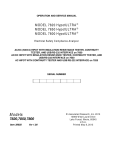
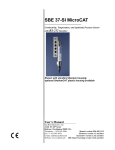
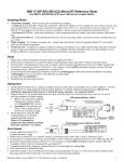
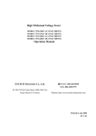
1
SBE 37-SI MicroCAT
Conductivity and Temperature Monitor
with RS-485 Interface
User’s Manual
Sea-Bird Electronics, Inc.
th
1808 136 Place NE
Bellevue, Washington 98005 USA
Tel: 425/643-9866
Fax:425/643-9954
Manual Version #006, 02/28/02
Firmware Version 2.2 and later
Limited Liability Statement
Extreme care should be exercised when using or servicing this equipment. It should be used or serviced only by
personnel with knowledge of and training in the use and maintenance of oceanographic electronic equipment.
SEA-BIRD ELECTRONICS, INC. disclaims all product liability risks arising from the use or servicing of this
system. SEA-BIRD ELECTRONICS, INC. has no way of controlling the use of this equipment or of choosing
the personnel to operate it, and therefore cannot take steps to comply with laws pertaining to product liability,
including laws which impose a duty to warn the user of any dangers involved in operating this equipment.
Therefore, acceptance of this system by the customer shall be conclusively deemed to include a covenant by the
customer to defend, indemnify, and hold SEA-BIRD ELECTRONICS, INC. harmless from all product liability
claims arising from the use or servicing of this system.
2
Table of Contents
Table of Contents
Section 1: Introduction ........................................................................ 5
About this Manual............................................................................................. 5
How to Contact Sea-Bird .................................................................................. 5
Quick Start ........................................................................................................ 5
Unpacking the MicroCAT................................................................................. 6
Section 2: Description of the MicroCAT............................................ 7
System Description ........................................................................................... 7
Specifications .................................................................................................... 8
Dimensions........................................................................................................ 9
End Cap Connector ........................................................................................... 9
Sample Timing ................................................................................................ 10
Section 3: Preparing the MicroCAT for Deployment .................... 11
Anti-Foul Material Check ............................................................................... 11
Power and Communications Test.................................................................... 12
Test Set-Up .............................................................................................. 12
Test........................................................................................................... 13
Section 4: Deploying and Operating the MicroCAT...................... 17
Set-Up for Deployment ................................................................................... 17
Deployment ..................................................................................................... 18
Operation Description ..................................................................................... 19
Setup and Sampling Example.......................................................................... 20
Timeout Description........................................................................................ 20
Command Descriptions ................................................................................... 20
MicroCAT Communication Microcontroller Commands ........................ 21
MicroCAT Acquisition Microcontroller Commands ............................... 23
Data Output Formats ....................................................................................... 28
Data Output after sending DATAii Command......................................... 28
Data Output after sending Operating Command (#iiTS, #iiTSR, #iiTSS,
#iiSL, #iiSLT) .......................................................................................... 28
Recovery ......................................................................................................... 29
Section 5: Routine Maintenance and Calibration .......................... 30
Corrosion Precautions ..................................................................................... 30
Conductivity Cell Maintenance....................................................................... 30
Routine Rinsing after Recovery ............................................................... 30
Cleaning ................................................................................................... 30
Sensor Calibration ........................................................................................... 32
Conductivity Sensor Calibration .............................................................. 32
Temperature Sensor Calibration............................................................... 32
Pressure Sensor (optional) Calibration..................................................... 32
Replacing Anti-Foul Cylinders ....................................................................... 33
Glossary............................................................................................... 34
3
Table of Contents
Appendix I: Functional Description ................................................. 35
Sensors ............................................................................................................ 35
Sensor Interface............................................................................................... 35
Appendix II: Electronics Disassembly/Reassembly ........................ 36
Disassembly .................................................................................................... 36
Reassembly...................................................................................................... 37
Appendix III: Command Summary ................................................. 38
Appendix IV: Replacement Parts ..................................................... 41
Index .................................................................................................... 42
Warranty Policy
Service Information
Calibration Certificates
Pressure Test Certificate
Application Notes
Schematics
4
Section 1: Introduction
Section 1: Introduction
This section includes contact information, Quick Start procedure, and photos
of a standard MicroCAT shipment.
About this Manual
This manual is to be used with the SBE 37-SI MicroCAT Conductivity and
Temperature Monitor (pressure optional) with RS-485 interface.
It is organized to guide the user from installation through operation and data
collection. We’ve included detailed specifications, command descriptions,
maintenance and calibration information, and helpful notes throughout
the manual.
Sea-Bird welcomes suggestions for new features and enhancements of our
products and/or documentation. Please e-mail any comments or suggestions to
[email protected].
How to Contact Sea-Bird
Sea-Bird Electronics, Inc.
1808 136th Place Northeast
Bellevue, Washington 98005 USA
Telephone:
Fax:
E-mail:
Website:
425-643-9866
425-643-9954
[email protected]
http://www.seabird.com
Business hours:
Monday-Friday, 0800 to 1700 Pacific Standard Time
(1600 to 0100 Universal Time)
Except from April to October, when we are on ‘summer time’
(1500 to 0000 Universal Time)
Quick Start
Follow these steps to get a Quick Start using the MicroCAT.
The manual provides step-by-step details for performing each task:
1.
Test power and communications (see Section 3: Preparing the MicroCAT
for Deployment).
2.
Deploy the MicroCAT (see Section 4: Deploying and Operating the
MicroCAT):
A. Set date and then time.
B. Establish setup parameters.
C. Remove protective plugs from anti-foul cups, and verify anti-foul
cylinders are installed. Leave protective plugs off for deployment.
D. Install I/O cable connector and locking sleeve.
E. Deploy MicroCAT, using optional Sea-Bird mounting hardware or
customer-supplied hardware.
5
Section 1: Introduction
Unpacking the MicroCAT
Shown below is a typical MicroCAT shipment.
SBE 37-SI MicroCAT
User Manual
I/O Cable
Spare parts kit
6
Software and Software Manuals
9-pin adapter
Cell cleaning solution
(Triton-X)
Section 2: Description of the MicroCAT
Section 2: Description of the MicroCAT
This section describes the functions and features of the
SBE 37-SI MicroCAT, including specifications and dimensions.
System Description
The SBE 37-SI MicroCAT is a high-accuracy, externally powered,
conductivity and temperature (pressure optional) monitor, which includes an
RS-485 interface. Designed to be incorporated into oceanographic sensing
systems, MicroCATs have non-corroding titanium housings rated for
operation to 7000 meters (23,000 feet) or pressure sensor full-scale range.
Communication with the MicroCAT is over a 2-wire, RS-485 link. Commands
can be sent to the MicroCAT to provide status display, data acquisition setup,
and diagnostic tests. A command to take a sample can be sent globally to all
MicroCATs on the RS-485 line or to an individual MicroCAT. Each
MicroCAT then holds the data in a buffer until it receives a command to
transmit the data.
Calibration coefficients stored in EEPROM allow the MicroCAT to transmit
data in engineering units. The MicroCAT retains the temperature and
conductivity sensors used in the SBE 16 SEACAT C-T Recorder, but has
improved acquisition electronics that increase accuracy and resolution, and
lower power consumption. The MicroCAT’s aged and pressure-protected
thermistor has a long history of exceptional accuracy and stability (typical drift
is less than 0.002 °C per year). Electrical isolation of the conductivity
electronics eliminates any possibility of ground-loop noise.
The MicroCAT’s internal-field conductivity cell is immune to proximity errors
and unaffected by external fouling. Expendable anti-fouling devices inhibit
internal fouling. A plastic cup with threaded cover at each end of the cell
retains the anti-foul material. The toxin quantity is typically sufficient for at
least two year’s deployment.
Notes:
• See SEATERM’s Help files
for detailed information on the
use of the program.
• Sea-Bird also supplies a DOS
software package,
SEASOFT-DOS, that can be
used with the MicroCAT.
However, this manual details
only the use of the Windows
software with the MicroCAT.
A software manual on
CD-ROM contains detailed
information on the setup and
use of SEASOFT-DOS.
The MicroCAT's optional pressure sensor, developed by Druck, Inc., has a
superior new design that is entirely different from conventional 'silicon' types
in which the deflection of a metallic diaphragm is detected by epoxy-bonded
silicon strain gauges. The Druck sensor employs a micro-machined silicon
diaphragm into which the strain elements are implanted using semiconductor
fabrication techniques. Unlike metal diaphragms, silicon's crystal structure is
perfectly elastic, so the sensor is essentially free of pressure hysteresis.
Compensation of the temperature influence on pressure offset and scale is
performed by the MicroCAT's CPU.
The MicroCAT is supplied with a powerful Win 95/98/NT software package,
SEASOFT-Win32. SEASOFT-Win32 includes SEATERM, a terminal
program for easy communication and data retrieval. SEATERM can send
commands to the MicroCAT to provide status display, data acquisition setup,
data display and capture, and diagnostic tests. Note that SEATERM does not
process the data.
7
Section 2: Description of the MicroCAT
Specifications
Note:
Pressure ranges are expressed
in meters of deployment depth
capability.
Measurement
Range
Temperature
(°C)
Conductivity
(S/m)
Optional Pressure
-5 to +35
0 to 7
(0 to 70 mS/cm)
0 to full scale
range:
20 / 100 / 350 /
1000 / 2000 /
3500 / 7000 meters
Initial
Accuracy
0.002
0.0003
(0.003 mS/cm)
0.1% of
full scale range
Typical
Stability
(per month)
0.0002
0.0003
(0.003 mS/cm)
0.004% of
full scale range
Resolution *
0.0001
0.00001
(0.0001 mS/cm)
0.002% of full
scale range
+1 to +32
0 to 6; physical
calibration over
the range 2.6 to
6 S/m, plus zero
conductivity (air)
Ambient pressure
to full scale range
in 5 steps
Sensor
Calibration
Counter
Time-Base
Quartz TCXO, ±2 ppm per year aging;
±5 ppm vs. temperature (-5 to +30 °C)
Real-Time
Clock
Watch-crystal type 32,768 Hz; corrected for drift and aging
by comparison to MicroCAT counter time-base to produce
overall ± 5 ppm accuracy (±2.6 minutes/year)
External
Input Power
9-24 VDC
Quiescent Current: 30 microamps
Sampling Current:
34.3 milliamps at 9 V
32.8 milliamps at 11 V
31.9 milliamps at 13 V
31.4 milliamps at 15 V
Communicating Current: 1.1 milliamps
Materials
Titanium pressure case rated at 7000 meters (23,000 feet)
Weight (without
pressure
sensor)
In water: 1.9 kg (4.3 lbs)
In air: 2.9 kg (6.5 lbs)
*Resolution
Typical RMS noise with fixed resistors on the temperature and conductivity
inputs (Tnom = 9.6, Cnom = 3.4):
NCYCLES
Temperature
Conductivity
(°C)
(S/m)
2
4
8
16
0.000193
0.000124
0.000095
0.000078
0.000042
0.000023
0.000018
0.000015
See Section 4: Deploying and Operating the MicroCAT for a description
of NCYCLES.
8
Section 2: Description of the MicroCAT
Dimensions
Dimensions in millimeters (inches)
Pressure
port
19.0
(0.75)
139.7
(5.50)
87.6
(3.45)
67.3
(2.65)
102.9
(4.05)
108.0
(4.25)
62.2
(2.45)
Diameter
27.9
(1.10)
47.5
(1.87)
241.3
(9.50)
Clamp
6.63
(0.261)
Diameter
4 places
436.9
(17.20)
292.1
(11.50)
Guide
19.0
(0.75)
113.8
(4.48)
108.0
87.6
(3.45) (4.25)
Standard Without
Mounting Hardware
Optional Wire Mounting
Clamp and Guide
End Cap Connector
= standard XSG connector
= optional MCBH connector
9
Optional Flat Surface
Mounting Brackets
Section 2: Description of the MicroCAT
Sample Timing
Take Sample Timing, which is the end of the Take Sample command
(#iiTS or #iiTSR) to the beginning of the reply:
Note:
See Section 4: Deploying and
Operating the MicroCAT for a
description of NCYCLES.
Pressure Sensor?
With Pressure Sensor
Without Pressure Sensor
NCYCLES
1
2
4
8
1
2
4
8
Time (seconds)
1.09
1.25
1.59
2.26
0.81
0.94
1.21
1.74
Power-On Time for each sample while logging:
Pressure Sensor?
With Pressure Sensor
Without Pressure Sensor
10
NCYCLES
2
4
8
16
2
4
8
16
Time (seconds)
2.44
2.77
3.44
4.77
2.07
2.34
2.87
3.92
Section 3: Preparing the MicroCAT for Deployment
Section 3:
Preparing the MicroCAT for Deployment
This section describes the pre-check procedure for preparing the MicroCAT
for deployment. Checking anti-foul material and testing power and
communications are discussed.
Anti-Foul Material Check
New MicroCATs are shipped with anti-foul cylinders and protective plugs
pre-installed. Verify that the cylinders are in the anti-foul cups.
See Section 5: Routine Maintenance and Calibration for details on
replacing the anti-foul cylinders.
Anti-foul
cylinder
The protective plugs must be removed prior to deployment or
pressurization. If the plugs are left in place during deployment, the sensor
will not register conductivity. If left in place during pressurization, the cell
may be destroyed.
Protective
plug
Plug
Cap
Cup
11
Section 3: Preparing the MicroCAT for Deployment
Power and Communications Test
The power and communications test will verify that the system works,
prior to deployment.
Note:
It is possible to use the MicroCAT
without SEATERM by sending
direct commands from a dumb
terminal or terminal emulator,
such as Windows HyperTerminal.
Test Set-Up
1.
If not already installed, install SEATERM on your computer using the
supplied software CD:
A. Insert the CD in your CD drive.
B. Double click on Seasoft-Win32.exe.
C. Follow the dialog box directions to install the software.
The default location for the software is c:/Program Files/Sea-Bird. Within
that folder is a sub-directory for each program.
2.
By hand, unscrew the locking sleeve from the MicroCAT’s bulkhead
connector. If you must use a wrench or pliers, be careful not to loosen
the bulkhead connector instead of the locking sleeve.
3.
Remove the dummy plug from the MicroCAT’s I/O bulkhead connector
by pulling the plug firmly away from the connector.
4.
Install the Sea-Bird I/O cable connector, aligning the raised bump
on the side of the connector with the large pin (pin 1 - ground) on
the MicroCAT.
5.
Connect the I/O cable connector to your computer’s serial port.
A 25-to-9 pin adapter is supplied for use if your computer has a 9-pin
serial port.
6.
Connect the I/O cable connector’s red (+) and black (-) wires to a power
supply (9-24 VDC).
Locking sleeve
Dummy plug
Note:
Refer to the Schematics at
the back of the manual for
I/O Cable pin-outs.
RS-485 A
Pin 2
RS-485 B
Pin 3
Ground Pin 1 (large) –
align with raised bump
on connector
External Power (9-24 VDC)
Pin 4
12
Section 3: Preparing the MicroCAT for Deployment
Test
Proceed as follows:
Note:
See SEATERM’s help files for
detailed information on the use
of the program.
1.
Double click on SeaTerm.exe. If this is the first time the program is used,
the setup dialog box appears:
Select the instrument type (SBE 37) and the computer COM port for
communication with the MicroCAT. Click OK.
2.
The main screen looks like this:
Menus
Toolbar
Command/Data Echo Area
Status bar
Computer
COM port
Instrument
Note:
There is at least one way, and as
many as three ways, to enter
a command:
• Manually type a command in
Command/Data Echo Area
• Use a menu to automatically
generate a command
• Use a Toolbar button to
automatically generate
a command
Note:
Once the system is configured and
connected (Steps 3 and 4 below),
to update the Status bar:
• on the Toolbar, click Status; or
• from the Utilities menu, select
Instrument Status.
SEATERM sends the status
command, which displays in the
Command/Data Echo Area, and
updates the Status bar.
Instrument
EPROM version
•
•
•
•
Upload
parameter
Capture
to file
status –
grayed
out if not
capturing
Baud rate, data bits,
stop bits, and parity
Menus – Contains tasks and frequently executed instrument
commands.
Toolbar – Contains buttons for frequently executed tasks and
instrument commands. All tasks and commands accessed through the
Toolbar are also available in the Menus. To display or hide the
Toolbar, select View Toolbar in the View menu. Grayed out Toolbar
buttons are not applicable.
Command/Data Echo Area – Echoes a command executed using a
Menu or Toolbar button, as well as the instrument’s response.
Additionally, a command can be manually typed in this area, from the
available commands for the instrument. Note that the instrument must
be awake for it to respond to a command (use the Connect button on
the Toolbar to wake up the instrument).
Status bar – Provides status information. To display or hide the Status
bar, select View Status bar in the View menu.
13
Section 3: Preparing the MicroCAT for Deployment
Following are the Toolbar keys applicable to the MicroCAT::
Toolbar
Button
Connect
Description
Equivalent
Command*
(press Enter
key)
Re-establish communications with MicroCAT.
Computer responds with S> prompt. MicroCAT
goes to sleep after two minutes without
communication from computer have elapsed.
Status
Display instrument setup and status.
#iiDS
Coefficients Display calibration coefficients.
#iiDC
Capture
Capture instrument responses on screen to file.
—
As MicroCAT has no internal memory, you
must capture before sampling begins to save
data for future processing. File has .cap
extension. Press Capture again to turn off
capture. Capture status displays in Status bar.
Diagnostics Perform one or more diagnostic tests on
#iiDS, #iiDC,
MicroCAT. Diagnostic test(s) accessed in this
#iiTS, and
manner are non-destructive – they do not write
#iiTSR
over any existing instrument settings.
Stop
Interrupt and end current activity, such as a
—
diagnostic test.
Disconnect Free computer COM port used to communicate
—
with MicroCAT. COM port can then be used by
another program. Note that MicroCAT must be
connected to COM port for data to be obtained.
*See Command Descriptions in Section 4: Deploying and Operating
the MicroCAT.
14
Section 3: Preparing the MicroCAT for Deployment
3.
In the Configure menu, select SBE 37. The dialog box looks
like this:
Interface for communication
between computer and
MicroCAT.
Computer COM port,
baud rate, data bits, and
parity for communication
between computer and
MicroCAT.
Automatically get ID
when only one
MicroCAT is connected;
Prompt ID if multiple
MicroCATs are online.
Make the selections in the Configuration Options dialog box:
• COMM Port: 1 through 10, as applicable
• Baud Rate: 9600 (documented on front cover of this manual)
• Data Bits: 8
• Parity: None
• Mode: RS-485 (Half Duplex)
• Modem/RS 485 ID: Automatically get ID
Click OK to overwrite an existing configuration file, or click Save As to
save the configuration as a new filename.
4.
Click Connect on the Toolbar. The display looks like this:
. . . Communication Established
S>
This shows that correct communications between the computer and
MicroCAT has been established.
If the system does not respond as shown:
• Click the Connect button again or press the Enter key twice.
• Verify the correct instrument was selected in the Configure menu and
the settings were entered correctly in the Configuration Options
dialog box. Note that the baud rate is documented on the front cover
of this manual.
• Check cabling between the computer and MicroCAT.
15
Section 3: Preparing the MicroCAT for Deployment
Note:
The MicroCAT has a timeout
algorithm. If it does not receive a
command or sample data for
two minutes, it powers down its
communication circuits, placing
the MicroCAT in quiescent (sleep)
state and drawing minimal current.
If the system does not appear
to respond, click Connect on
the Toolbar to reestablish
communications.
5.
Confirm the MicroCAT has responded to the wake-up signal by typing
ID? and pressing the Enter key. The display looks like this:
id=01
where 01 is the number set at the factory or by the previous user. See the
manual front cover for the factory-set identification (ID) number. Note
that the ID is stored in the MicroCAT’s EEPROM and can be changed so
that multiple MicroCATs on a single RS-485 line each have a unique ID.
Press the Enter key to get the S> prompt.
6.
Display MicroCAT status information by clicking Status on the Toolbar.
The display looks like this:
(where ii=MicroCAT ID)
S>#iiDS
SBE37-SI 485 V 2.2 SERIAL NO. 0011 07 Aug 2000 08:49:08
sample interval = 30 seconds (not applicable to the 37-SI)
do not output salinity with each sample
do not output sound velocity with each sample
do not output density with each sample
do not output depth with each sample
latitude to use for depth calculation = 0.00 deg
reference pressure = 0.0 db
A/D cycles to average = 4
temperature = 7.54 deg C
S>
7.
Command the MicroCAT to take a sample by typing #iiTS
(ii = MicroCAT ID) and pressing the Enter key. The display looks like
this (if do not output salinity, sound velocity, density, or depth with each
sample displayed in response to the status command in Step 6):
12345, 23.7658, 0.00019 0.062, 07 Aug 2000, 16:30:43
where
12345 = MicroCAT serial number
23.7658 = temperature in degrees Celsius
0.00019 = conductivity in S/m
0.062 = pressure in dBars
07 Aug 2000 = date (default upon power-up is 01 Jan 1980)
16:30:43 = time (default upon power-up is 00:00:00)
Note:
For reliable operation, all
commands may need to be
preceded with two @ characters in
order to clear the communication
microcontroller receive buffers.
Example (take sample command
for MicroCAT with ID=01):
S>@@#01TS
These numbers should be reasonable; i.e., room temperature,
zero conductivity, barometric pressure (gauge pressure), current date and
time (Pacific Daylight or Standard Time).
8.
Command the MicroCAT to go to sleep (quiescent state) by typing #iiQS
(ii = MicroCAT ID) and pressing the Enter key.
The MicroCAT is ready for programming and deployment.
16
Section 4: Deploying and Operating the MicroCAT
Section 4: Deploying and Operating
the MicroCAT
This section provides instructions for deploying the MicroCAT.
It also includes a discussion of system operation, an example set of operation
commands, and detailed command descriptions.
Set-Up for Deployment
Notes:
• Date and time are reset to 01 Jan
1980 when power is applied. If you
wish to use the built-in real-time
clock, set the date and time.
• It is always necessary to set both
date and then time. If a new date
is entered but not a new time,
the new date will not be saved.
Program the MicroCAT for the intended deployment (see Section 3: Preparing
the MicroCAT for Deployment for connection information; see information in
this section on commands):
1.
Set the date and time. Note that the date and time can be set individually
for each MicroCAT (#iiMMDDYY= or #iiDDMMYY= to set date;
#iiHHMMSS= to set time), or globally for all MicroCATs online
(MMDDYY= or DDMMYY= to set date; HHMMSS= to set time).
2.
Establish the setup parameters.
3.
If the system will have multiple MicroCATs online, verify the MicroCAT
is set to Prompt ID to allow use of the Toolbar buttons and Menus:
A. In the Configure menu, select SBE 37.
B. Click on the COM Settings tab.
C. For Modem/RS485 ID, click on Prompt ID.
D. Click OK or Save As.
17
Section 4: Deploying and Operating the MicroCAT
Deployment
The MicroCAT can be mounted with customer-supplied hardware or can be
ordered with pre-installed Sea-Bird mounting brackets.
1.
Install customer-supplied mounting equipment (if Sea-Bird mounting
clamp and guide or brackets are not pre-installed):
A. Install a mounting bracket that attaches to the tapped holes in the
MicroCAT sensor end cap. Use titanium hardware to attach the
mounting bracket to the MicroCAT, and place non-metallic material
between the titanium housing and any dissimilar metal in the bracket.
Do not drill any holes in the MicroCAT.
B. Ensure the mounting scheme does not transfer mooring throughtension to the sensor end cap, which could pull off the end cap.
2.
Remove the protective plugs, if installed, from the anti-foul cups.
Verify that the two plastic cups contain anti-foul cylinders (see Section 5:
Routine Maintenance and Calibration for anti-foul cylinder replacement).
Leave the protective plugs off for deployment.
3.
Install the I/O cable on the MicroCAT:
A. Lightly lubricate the inside of the cable connector with silicone
grease (DC-4 or equivalent).
B. Install the cable connector, aligning the raised bump on the side of the
connector with the large pin (pin 1 - ground) on the MicroCAT.
Remove any trapped air by burping or gently squeezing the connector
near the top and moving your fingers toward the end cap.
C. Place the locking sleeve over the connector. Tighten the locking
sleeve finger tight only. Do not overtighten the locking sleeve and
do not use a wrench or pliers.
4.
Attach the mounting equipment to the mooring cable or support.
5.
Verify that the hardware and external fittings are secure.
6.
Connect the MicroCAT to the computer and power supply.
(See Power and Communications Test in Section 3: Preparing the
MicroCAT for Deployment.)
Sea-Bird
mounting
clamp and
guide or flat
surface
mounting
brackets
Tapped
holes
Remove
plugs (2)
Cups (2)
I/O cable connector
Locking sleeve
18
Section 4: Deploying and Operating the MicroCAT
Operation Description
The MicroCAT’s internal functions are supervised by two internal
microcontrollers. The acquisition microcontroller supervises measurement
acquisition, and setup and sampling functions. The communication
microcontroller supervises communication between the MicroCAT and
computer. These two microcontrollers allow for independent control of power
usage by the communications and acquisition circuits. Acquisition consumes
more power, but for shorter duration. Communications protocols take
proportionately more time, but can be controlled separately and are operated at
lower power. This also prevents communications protocols from interfering
with measurement acquisition timing.
Commands can be directed to the MicroCAT communication microcontroller
or its acquisition microcontroller. A command prefix (!ii or #ii) is used to
direct commands to a MicroCAT with the same ID (ii = ID):
• !ii directs command to Communication Microcontroller
• #ii directs command to Acquisition Microcontroller
Global commands do not require a prefix and are recognized by all
MicroCATs attached to the RS-485 interface.
•
•
•
•
•
MicroCAT Communication
Microcontroller
Get Data
Set MicroCAT ID
Display Firmware version
Global commands to get
data, set clock, and power off
Set baud rate
19
•
•
•
•
•
•
MicroCAT Acquisition
Microcontroller
Status
Setup
Operating
Averaging
Testing
Calibration Coefficients
Section 4: Deploying and Operating the MicroCAT
Setup and Sampling Example
An example follows for a system with two MicroCATs (IDs 01 and 02)
online. Note that the MicroCATs’ response to each command is not shown
in the example. Review the commands described in Command Descriptions
and the example below before setting up your system.
Example: Wake up all MicroCATs. Globally set date and time for
all MicroCATs to September 7, 2000, 09:43:00. Set up all
MicroCATs to output salinity. Command all MicroCATs to take a
sample and hold data in buffer, and then command each
MicroCAT to transmit data from buffer. Repeat sampling
sequence a number of times. Request all MicroCATs to get
average data and hold average in buffer, and start next averaging
cycle. Then command each MicroCAT to transmit average data
from buffer. Send power-off command to all MicroCATs.
(Click Connect on Toolbar to wake up all MicroCATs.)
S>MMDDYY=090700
S>HHMMSS=094300
S>#01OUTPUTSAL=Y
S>#02OUTPUTSAL=Y
S>STARTSAMPLE
S>DATA01
S>DATA02
(Repeat STARTSAMPLE through DATA02 commands a
number of times - If MicroCATs have gone to sleep between
samples, click Connect on Toolbar to wake up.)
S>ADATA
S>DATA01
S>DATA02
S>PWROFF
Timeout Description
The MicroCAT has a timeout algorithm. If the MicroCAT does not receive a
command for two minutes, it powers down its communication circuits. This
places the MicroCAT in quiescent state, drawing minimal current. To reestablish control, press Connect on the Toolbar or press the Enter key.
The system responds with the S> prompt.
Command Descriptions
This section describes commands and provides sample outputs.
See Appendix III: Command Summary Table for a summarized command list.
Note:
For reliable operation, all
commands may need to be
preceded with two @ characters to
clear the communication
microcontroller receive buffers.
Example (status command for
MicroCAT 01):
S>@@#01DS
When entering commands:
• Input commands to the MicroCAT in upper or lower case letters, and
register commands by pressing the Enter key.
• The MicroCAT sends ‘? CMD’ if an invalid command is entered.
• If the system does not return an S> prompt after executing a command,
press the Enter key to get the S> prompt.
• If a new command is not received within two minutes after the completion
of a command, the MicroCAT returns to the quiescent (sleep) state.
• If in quiescent state, re-establish communications by pressing Connect on
the Toolbar or pressing the Enter key to get an S> prompt.
20
Section 4: Deploying and Operating the MicroCAT
MicroCAT Communication Microcontroller Commands
Global Commands
Notes:
• Date and time are reset to
01 Jan 1980 when power is first
applied. If you wish to use the
built-in real-time clock, set the
date and time.
• DDMMYY= and MMDDYY=
commands are equivalent. Either
can be used to set the date.
• It is always necessary to set both
date and then time. If a new date
is entered but not a new time,
the new date will not be saved.
ADATA
Command all MicroCATs to get average
data from acquisition units and start next
averaging cycle. Communication
microcontrollers send SACG command
(send averaged, converted data and start
new average) to acquisition
microcontrollers. Averaged data is held in
communication microcontroller buffers
until receiving DATAii command.
GDATA
Command all MicroCATs to get one
sample. Communication microcontrollers
send command to acquisition
microcontrollers to take sample and turn
power off. Data is held in communication
microcontroller buffers until receiving
DATAii command.
STARTSAMPLE
Command all MicroCATs to get one
sample. Communication microcontrollers
send command to acquisition
microcontrollers to take sample and leave
power on. Data is held in communication
microcontroller buffers until receiving
DATAii command. Send this command
once before using GSAMPLE command.
GSAMPLE
Command all MicroCATs to get last
sample and then take new sample.
Communication microcontrollers send
#iiSL command to acquisition
microcontrollers, and then send #iiTS
command to acquisition microcontrollers
once #iiSL reply is received. Data from
last sample is held in communication
microcontroller buffers until receiving
DATAii command; data from new
sample is held in acquisition
microcontroller buffers.
MMDDYY=mmddyy
Set real-time clock month, day, and year
for all MicroCATs. This must be followed
by HHMMSS= command to set time.
DDMMYY=ddmmyy
Set real-time clock day, month, and year
for all MicroCATs. This must be followed
by HHMMSS= command to set time.
HHMMSS=hhmmss
Set real-time clock hour, minute,
and second for all MicroCATs.
PWROFF
Quit session and place all MicroCATs in
quiescent (sleep) state. Main power is
turned off.
21
Section 4: Deploying and Operating the MicroCAT
Get Data Command
Get data obtained with GDATA, ADATA,
STARTSAMPLE, or GSAMPLE
command from MicroCAT with ID = ii.
DATAii
MicroCAT ID Commands
Only one MicroCAT can be online when sending these commands.
ID?
Get MicroCAT ID
(ID = ii, where ii= 0-99).
*ID=ii
Set MicroCAT ID to ii, where ii= 0-99.
This command must be sent twice,
because the computer requests
verification. Note that if more than one
MicroCAT is online when sending this
command, all MicroCATs online will be
set to same ID.
Miscellaneous Commands
All these commands are preceded by !ii, where ii=MicroCAT ID (0-99).
Notes:
The MicroCAT’s baud rate (set with
!iiBAUD command) must be the
same as SEATERM’s baud rate
(set in the Configure menu).
!iiDS
Display MicroCAT communication
microcontroller firmware version.
!iiBAUD=x
x= baud rate (1200, 2400, 4800, or 9600).
!ii*EETEST
Test EEPROM. This test erases all
calibration coefficients and userprogrammed parameters.
22
Section 4: Deploying and Operating the MicroCAT
MicroCAT Acquisition Microcontroller Commands
All Acquisition Microcontroller Commands are preceded by #ii,
where ii= MicroCAT ID (0-99).
Status Command
Note:
If the external voltage is below
6.15 volts, the following displays in
response to the status command:
WARNING: LOW BATTERY
VOLTAGE!!
Display operating status and setup
parameters. Equivalent to Status button on
Toolbar.
#iiDS
List below includes, where applicable,
command used to modify parameter.
• firmware version, serial number, date
and time [#iiMMDDYY= or
#iiDDMMYY=, and #iiHHMMSS=]
• sample interval time
(not applicable to SBE 37-SI)
• salinity output with each sample?
[#iiOUTPUTSAL=]
• sound velocity output with each
sample? [#iiOUTPUTSV=]
• density output with each sample?
[#iiOUTPUTDENSITY=]
• depth output with each sample?
[#iiOUTPUTDEPTH=]
• latitude for depth calculation
[#iiLATITUDE=]
• reference pressure [#iiREFPRESS=]
• A/D cycles to average per sample
[#iiNCYCLES=]
• current temperature
Example: Display status for MicroCAT with ID=01.
S>#01DS
SBE37-SI 485 V 2.2 SERIAL NO. 0011 07 Aug 2000 08:49:08
sample interval = 30 seconds (not applicable to SBE 37-SI)
output salinity with each sample
output sound velocity with each sample
output density with each sample
output depth with each sample
latitude to use for depth calculation = 0.00 deg
reference pressure = 0.0 db
A/D cycles to average = 4
temperature = 7.54 deg C
23
Section 4: Deploying and Operating the MicroCAT
Setup Commands
Notes:
• Date and time are reset to
01 Jan 1980 when power is first
applied. If you wish to use the
built-in real-time clock, set the
date and time.
• #iiDDMMYY= and #iiMMDDYY=
commands are equivalent. Either
can be used to set the date.
• It is always necessary to set both
date and then time. If a new date
is entered but not a new time,
the new date will not be saved.
#iiMMDDYY=mmddyy
Set real-time clock month, day, and year.
This command must be followed by
#iiHHMMSS= command to set time.
#iiDDMMYY=ddmmyy
Set real-time clock day, month, and year.
This command must be followed by
#iiHHMMSS= command to set time.
#iiHHMMSS=hhmmss
Set real-time clock hour, minute,
and second.
Example: Set current date and time for MicroCAT with ID=01 to
10 January 2000 12:00:00.
S>#01MMDDYY=011000
S>#01HHMMSS=120000
or
S>#01DDMMYY=100100
S>#01HHMMSS=120000
Notes:
See Data Output Formats below
for details.
#iiFORMAT=x
x=0: output raw hex data, for diagnostic
use at Sea-Bird
x=1 (default) – output converted data:
date format dd mmm yyyy, hh:mm:ss
x=2 – output converted data:
date format mm-dd-yyyy, hh:mm:ss
#iiOUTPUTSAL=x
x=Y: Calculate and output salinity (psu)
with each sample.
x=N (default): Do not.
#iiOUTPUTSV=x
x=Y: Calculate and output sound velocity
(m/sec) with each sample, using Chen and
Millero formula (UNESCO Technical
Papers in Marine Science #44).
x=N (default): Do not.
#iiOUTPUTDEPTH=x
x=Y: Calculate and output depth (meters)
with each sample.
x=N (default): Do not.
#iiOUTPUTDENSITY=x
x=Y: Calculate and output local density
sigma (kg/m3) with each sample, based on
salinity, temperature, and pressure.
Sigma (s, t, p) = density - 1000 kg/m3
x=N (default): Do not.
#iiLATITUDE=x
24
x = latitude (degrees) to use in depth
calculation. Entry is ignored if
#iiOUTPUTDEPTH=N.
Section 4: Deploying and Operating the MicroCAT
Setup Commands (continued)
Note:
When communicating with
multiple instruments, use PWROFF
to send a power off command to
all MicroCATs simultaneously. If
the #iiQS command is sent
sequentially to each MicroCAT,
activity on the line may wake up a
quiescent MicroCAT.
#iiREFPRESS=x
x = reference pressure (gauge) in decibars.
MicroCAT without installed pressure
sensor uses this reference pressure in
conductivity, salinity, and
sound velocity calculation. Entry is
ignored if MicroCAT has pressure sensor.
#iiNCYCLES=x
x= number of A/D cycles to average
(range 1 to 127; default 4). Increasing
#iiNCYCLES increases measurement
resolution and time required for
measurement. See Sample Timing in
Section 2: Description of the MicroCAT.
#iiQS
Quit session and place MicroCAT in
quiescent (sleep) state. Main power is
turned off. Equivalent to communication
microcontroller PWROFF command, but
applies only to specified MicroCAT.
Operating Commands
Note:
The MicroCAT has a buffer that
stores the most recent data sample.
Data in the buffer is erased upon
removal or failure of power.
These commands are used by an external controller to request a sample from
the MicroCAT.
#iiTS
Take sample, output converted data, and
leave power on.
#iiTSR
Take sample, output raw data, and leave
power on.
#iiTSS
Take sample, output converted data, and
turn power off.
#iiSL
Output converted data from last sample,
and leave power on.
#iiSLT
Output converted data from last sample,
then take new sample, and leave power on.
25
Section 4: Deploying and Operating the MicroCAT
Averaging Commands
Note:
These commands related to
averaging are typically used only
for customized acquisition.
ADATA and DATAii commands
more easily start averaging and get
averaged data. See MicroCAT
Communication Microcontroller
Commands above for details.
These commands are used by an external controller to request a sample from
the MicroCAT.
#iiGA
Start averaging data.
#iiSACG
Output averaged data, converted.
Start new average.
#iiSARG
Output averaged data, raw.
Start new average.
#iiSAC
Output averaged data, converted.
Continue averaging.
#iiSAR
Output averaged data, raw.
Continue averaging.
Testing Commands
#iiTT
Measure temperature for 30 samples
or until Esc key is pressed, output
converted data.
#iiTC
Measure conductivity for 30 samples
or until Esc key is pressed, output
converted data.
#iiTP
Measure pressure for 30 samples or until
Esc key is pressed, output converted data.
#iiTTR
Measure temperature for 30 samples or
until Esc key is pressed, output raw data.
#iiTCR
Measure conductivity for 30 samples or
until Esc key is pressed, output raw data.
#iiTPR
Measure pressure for 30 samples or until
Esc key is pressed, output raw data.
#iiTR
Measure real-time clock frequency for
30 samples or until Esc key is pressed,
output data.
#iiSS
Send averaged data statistics.
26
Section 4: Deploying and Operating the MicroCAT
Notes:
• Dates shown are when
calibrations were performed.
Calibration coefficients are
initially factory-set and
should agree with
Calibration Certificates
shipped with MicroCAT.
• See individual Coefficient
Commands below for definitions
of the data in the example.
Calibration Coefficients Commands
Display calibration coefficients.
#iiDC
Equivalent to Coefficients button
on Toolbar.
Example: Display coefficients for MicroCAT with ID=03, which
does not have a pressure sensor.
S>#03DC
SBE37-SI 485 V 2.2 0011
temperature:
08-apr-96
TA0 = -9.420702e-05
TA1 = 2.937924e-04
TA2 = -3.739471e-06
TA3 = 1.909551e-07
conductivity:
09-apr-96
G = -1.036689e+00
H = 1.444342e-01
I = -3.112137e-04
J = 3.005941e-05
CPCOR = -9.570001e-08
CTCOR = 3.250000e-06
WBOTC = 1.968100e-05
rtc:
11-apr-96
RTCA0 = 9.999782e-01
RTCA1 = 1.749351e-06
RTCA2 = -3.497835e-08
The individual Coefficient Commands listed below are used to modify a
particular coefficient or date:
Note:
F = floating point number
S = string with no spaces
#iiTCALDATE=S
#iiTA0=F
#iiTA1=F
#iiTA2=F
#iiTA3=F
#iiCALDATE=S
#iiCG=F
#iiCH=F
#iiCI=F
#iiCJ=F
#iiWBOTC=F
#iiCTCOR=F
#iiCPCOR=F
#iiPCALDATE=S
#iiPA0=F
#iiPA1=F
#iiPA2=F
#iiPTCA0=F
#iiPTCA1=F
#iiPTCA2=F
#iiPTCB0=F
#iiPTCB1=F
#iiPTCB2=F
#iiPOFFSET=F
#iiRCALDATE=S
#iiRTCA0=F
#iiRTCA1=F
#iiRTCA2=F
27
S=Temperature calibration date
F=Temperature A0
F=Temperature A1
F=Temperature A2
F=Temperature A3
S=Conductivity calibration date
F=Conductivity G
F=Conductivity H
F=Conductivity I
F=Conductivity J
F=Conductivity wbotc
F=Conductivity ctcor
F=Conductivity cpcor
S=Pressure calibration date
F=Pressure A0
F=Pressure A1
F=Pressure A2
F=Pressure ptca0
F=Pressure ptca1
F=Pressure ptca2
F=Pressure ptcb0
F=Pressure ptcb1
F=Pressure ptcb2
F=Pressure offset
S=Real-time clock calibration date
F=Real-time clock A0
F=Real-time clock A1
F=Real-time clock A2
Section 4: Deploying and Operating the MicroCAT
Data Output Formats
Each scan ends with a carriage return <CR> and line feed <LF>. The exact
format of the output varies, depending on the command sent, the user’s
selection for the #iiFORMAT command, and whether additional parameters
(salinity, sound velocity, etc.) are calculated with the data.
Notes (for #iiFORMAT=1 or 2):
ii = MicroCAT ID
m = MicroCAT serial number
t = temperature (°C, ITS-90)
c = conductivity (S/m)
p = pressure (decibars); sent only if
optional pressure sensor installed
d = depth (meters), sent only if
#iiOUTPUTDEPTH=Y
s = salinity (psu); data sent only if
#iiOUTPUTSAL=Y
v = sound velocity (meters/second);
sent only if #iiOUTPUTSV=Y
r = density sigma (kg/m3), data sent
only if #iiOUTPUTDENSITY=Y
dd mmm yyyy = day, month, year
mm-dd-yyyy = month, day, year
hh:mm:ss = hour, minute, second
n = number of samples in average;
sent only if average data was
requested
• There is a comma but no space
between serial number, temperature,
and conductivity. All other data is
separated with a comma and space.
• Leading zeros are suppressed,
except for one zero to the left of the
decimal point.
• The MicroCAT’s pressure sensor is
an absolute sensor, so its raw output
includes the effect of atmospheric
pressure (14.7 psi). As shown on the
Calibration Sheet, Sea-Bird’s
calibration (and resulting calibration
coefficients) is in terms of psia.
However, when outputting pressure
in decibars, the MicroCAT outputs
pressure relative to the ocean
surface (i.e., at the surface the
output pressure is 0 decibars).
The MicroCAT uses the following
equation to convert psia to decibars:
pressure (db) =
[pressure (psia) - 14.7] * 0.689476
•
#iiFORMAT=0: raw hexadecimal data, intended only for diagnostic use
at Sea-Bird
•
#iiFORMAT=1 or 2: see below
Data Output after sending DATAii Command
•
#iiFORMAT=1 (default)
ii, mmmmm,ttt.tttt,cc.ccccc, pppp.ppp, dddd.ddd, sss.ssss, vvvv.vvv,
rrr.rrrr, hh:mm:ss, dd mmm yyyy, n
•
#iiFORMAT=2
ii, mmmmm,ttt.tttt,cc.ccccc, pppp.ppp, dddd.ddd, sss.ssss, vvvv.vvv,
rrr.rrrr, hh:mm:ss, mm-dd-yyyy, n
Example: Sample output from DATA02 command when pressure
sensor not installed, #02FORMAT=1, #02OUTPUTDEPTH=N,
#02OUTPUTDENSITY=N, #02OUTPUTSAL=N, and
#02OUTPUTSV=N:
02, 12345, 23.7658, 0.00019, 07 Aug 2000, 16:30:43
(ID, serial number, temperature, conductivity, date, time)
Data Output after sending Operating Command
(#iiTS, #iiTSR, #iiTSS, #iiSL, #iiSLT)
•
#iiFORMAT=1 (default)
mmmmm,ttt.tttt,cc.ccccc, pppp.ppp, dddd.ddd, sss.ssss, vvvv.vvv, rrr.rrrr,
hh:mm:ss, dd mmm yyyy
•
#iiFORMAT=2
mmmmm,ttt.tttt,cc.ccccc, pppp.ppp, dddd.ddd, sss.ssss, vvvv.vvv, rrr.rrrr,
hh:mm:ss, mm-dd-yyyy
28
Section 4: Deploying and Operating the MicroCAT
Recovery
WARNING!
Pressure housings may flood
under pressure due to dirty or
damaged o-rings, or other failed
seals, causing highly compressed
air to be trapped inside. If this
happens, a potentially lifethreatening explosion can occur
when the instrument is brought to
the surface.
If the MicroCAT is unresponsive to
commands or shows other signs
of flooding or damage, carefully
secure the instrument in a location
away from people until it has been
determined that abnormal internal
pressure does not exist.
Contact Sea-Bird for assistance
with procedures for safely
relieving internal pressure.
1.
Rinse the conductivity cell with fresh water. (See Section 5: Routine
Maintenance and Calibration for cell cleaning and storage.)
2.
Reinsert the protective plugs in the anti-foul cups.
29
Section 5: Routine Maintenance and Calibration
Section 5: Routine Maintenance
and Calibration
This section reviews corrosion precautions, cell storage, sensor calibration,
and replacement of anti-foul cylinders. The accuracy of the MicroCAT is
sustained by the care and calibration of the conductivity sensor and by
establishing proper handling practices.
Corrosion Precautions
All exposed metal is titanium; other materials are plastic. No corrosion
precautions are required, but avoid direct electrical connection of the
MicroCAT housing to mooring or other dissimilar metal hardware. Rinse the
MicroCAT with fresh water after use and prior to storage.
Conductivity Cell Maintenance
CAUTION:
Do not store the MicroCAT with
water in the conductivity cell.
Freezing temperatures (for example,
in Arctic environments or during air
shipment) can break the conductivity
cell if it is full of water.
The MicroCAT’s conductivity cell is shipped dry to prevent freezing in
shipping and depletion of the anti-foul cylinders.
Routine Rinsing after Recovery
After each recovery, rinse the cell with clean de-ionized water, drain, and
gently blow through the cell to remove larger water droplets. Do not use
compressed air, which typically contains oil vapor. Re-insert the protective
plugs in the anti-foul cups.
If the cell is not rinsed between usage, salt crystals may form on the platinized
electrode surfaces. When the instrument is used next, sensor accuracy may be
temporarily affected until these crystals dissolve.
Cleaning
CAUTION:
Do not put a brush or any object
inside the conductivity cell to
clean it. Putting an object inside the
cell can damage and break the cell.
Cell cleaning removes foreign material coating the inside of the cell, partially
restoring the cell to the original factory calibration. Decide whether to clean
the cell after a deployment based on the following:
•
Do not clean the cell if you will be sending the MicroCAT to Sea-Bird
for a post-cruise calibration to establish the drift during the cruise.
•
Clean the cell if you will not be performing a post-cruise calibration to
establish the drift.
Routine Cleaning (inside of cell not visibly dirty)
1. Fill the cell with a 1% solution of Triton X-100 (included with shipment)
and let it soak for 30 minutes.
2.
Drain and flush with warm, clean, de-ionized water for 1 minute. Then:
• Prepare for deployment, or
• If being stored – drain and gently blow through the cell to remove
larger water droplets. Do not use compressed air, which typically
contains oil vapor. Replace the protective plugs in the anti-foul cups.
30
Section 5: Routine Maintenance and Calibration
Acid Cleaning (visible deposits or marine growth on inside of cell)
Do not clean with acid more than once per week.
CAUTION:
Anti-foul cups are attached to the
guard and connecting with tubing to
the cell. Removing the guard
without disconnecting the cups
from the guard will break the cell.
1.
Remove the MicroCAT guard:
A. Remove the two screws attaching each anti-foul cup to the guard.
B. Remove the four Phillips-head screws attaching the guard to
the housing and sensor end cap.
C. Gently lift the guard away.
2.
Prepare for cleaning:
A. Remove the small section of Tygon tubing and anti-foul cup from one
end of the cell.
B. Place a 0.6 m (2 ft) length of 7/16 in. ID, 9/16 in. OD Tygon tubing
over the end of the cell.
C. Clamp the MicroCAT so that the cell is vertical, with the 0.6 m (2 ft)
Tygon tubing at the bottom end.
D. Loop the Tygon tubing into a ‘U’ shape, and tape the open end of the
tubing in place at the same height as the top of the glass cell.
3.
Clean the cell:
A. Pour muriatic acid (37% HCl) into the open end of the tubing until
the cell is nearly filled. Let it soak for 1 to 2 minutes only.
B. Drain the acid from the cell and flush for 5 minutes with warm (not
hot), clean, de-ionized water.
C. Rinse the exterior of the instrument to remove any spilled acid from
the surface.
D. Fill the cell with a 1% solution of Triton X-100 (included with
shipment) and let it stand for 5 minutes.
E. Drain and flush with warm, clean, de-ionized water for 1 minute.
F. Carefully remove the 0.6 m (2 ft) length of Tygon tubing.
4.
Reinstall the anti-foul cup and the guard:
A. Carefully reinstall the small section of Tygon tubing and anti-foul cup
on the end of the glass cell.
B. Carefully place the guard over the housing, aligning all holes.
C. Reinstall the two screws attaching each anti-foul cup to the guard.
D. Reinstall the four Phillips-head screws attaching the guard to the
housing and sensor end cap.
5.
Prepare for deployment, or
If being stored – gently blow through the cell to remove larger water
droplets. Do not use compressed air, which typically contains oil vapor.
Replace the protective plugs in the anti-foul cups.
WARNING!
Avoid breathing the acid fumes.
31
Section 5: Routine Maintenance and Calibration
Sensor Calibration
Note:
Please remove anti-foul cylinders
from the anti-foul cups before
returning the MicroCAT to Sea-Bird.
Store them for future use. See
Replacing Anti-Foul Cylinders for
the cylinder removal procedure.
Sea-Bird sensors are calibrated by subjecting them to known physical
conditions and measuring the sensor responses. Coefficients are then
computed which may be used with appropriate algorithms to obtain
engineering units. The conductivity, temperature, and optional pressure
sensors on the MicroCAT are supplied fully calibrated, with coefficients
printed on their respective Calibration Certificates (see back of manual). These
coefficients have been stored in the MicroCAT’s EEPROM.
We recommend that MicroCATs be returned to Sea-Bird for calibration.
Conductivity Sensor Calibration
The conductivity sensor incorporates a fixed precision resistor in parallel with
the cell. When the cell is dry and in air, the sensor’s electrical circuitry outputs
a frequency representative of the fixed resistor. This frequency is recorded on
the Calibration Certificate and should remain stable (within 1 Hz) over time.
The primary mechanism for calibration drift in conductivity sensors is the
fouling of the cell by chemical or biological deposits. Fouling changes the cell
geometry, resulting in a shift in cell constant.
Accordingly, the most important determinant of long-term sensor accuracy is
the cleanliness of the cell. We recommend that the conductivity sensors be
calibrated before and after deployment, but particularly when the cell has been
exposed to contamination by oil slicks or biological material.
Temperature Sensor Calibration
The primary source of temperature sensor calibration drift is the aging of the
thermistor element. Sensor drift will usually be a few thousandths of a degree
during the first year, and less in subsequent intervals. Sensor drift is not
substantially dependent upon the environmental conditions of use, and —
unlike platinum or copper elements — the thermistor is insensitive
to shock.
Pressure Sensor (optional) Calibration
The optional strain-gauge pressure sensor is a mechanical diaphragm type,
with an initial static error band of 0.05%. Consequently, the sensor is capable
of meeting MicroCAT’s 0.10% error specification with some allowance for
aging and ambient-temperature induced drift.
For demanding applications, or where the sensor’s air ambient pressure
response has changed significantly, calibration using a dead-weight
generator is recommended. The pressure sensor port uses a 7/16-20 straight
thread for mechanical connection to the pressure source.
(Refer to Application Note 12-1, found on Sea-Bird’s website, for the general
calibration procedure. The pressure sensor port thread size in the Application
Note is not applicable to the MicroCAT.)
32
Section 5: Routine Maintenance and Calibration
Replacing Anti-Foul Cylinders
WARNING!
• Anti-foul cylinders contain tributyl tin oxide (TBTO). Handle
the cylinders with gloves. If the
cylinders come in contact with
skin, wash with soap and water
immediately. Dispose of gloves
properly. Refer to the Material
Safety Data Sheet, enclosed with
the shipment, for details.
• Anti-foul cylinders are not
classified by the U.S. DOT or the
IATA as hazardous material, in the
quantities used by Sea-Bird.
Anti-foul cylinders have a useful deployment life of approximately 2 years.
Sea-Bird recommends that you keep track of how long the cylinders have been
deployed, to allow you to purchase and replace the cylinders when needed.
Handling the cylinders with gloves, follow this procedure to replace each
anti-foul cylinder (two):
Cup
Cap
Plug
Cap
The MicroCAT has an anti-foul cup and cap on each end of the cell.
New MicroCATs are shipped with an anti-foul cylinder and a protective
plug pre-installed in each cup.
1.
Remote the protective plug from the anti-foul cup.
2.
Unscrew the cap with a 5/8-inch socket wrench.
3.
Remove the old anti-foul cylinder. If the old cylinder is difficult
to remove:
• Use needle-nose pliers and carefully break up material.
• If necessary, remove the guard to provide easier access.
4.
Place the new anti-foul cylinder in the cup.
5.
Rethread the cap onto the cup. Do not over tighten.
6.
If the MicroCAT is to be stored, re-install the protective plug. Note that
the plugs must be removed prior to deployment or pressurization.
If the plugs are left in place during deployment, the cell will not
register conductivity. If left in place during pressurization, the cell
may be destroyed.
Cup
CAUTION:
Anti-foul cups are attached to the
guard and connected with tubing to the
cell. Removing the guard without
disconnecting the cups from the
guard will break the cell. If the guard
must be removed:
1. Remove the two screws connecting
each anti-foul cup to the guard.
2. Remove the four Phillips-head
screws connecting the guard to the
housing and sensor end cap.
3. Gently lift the guard away.
Notes:
• Please remove anti-foul cylinders
from the anti-foul cups before
returning MicroCATs to Sea-Bird.
• Store removed anti-foul cylinders in
a plastic bag, and keep them in a
cool place.
33
Glossary
Glossary
Anti-foul cylinders - Expendable devices saturated with a tri-butyl-tin
based toxin placed inside the anti-foul cups, located at the ends of the
conductivity cell.
Fouling - Biological growth in the conductivity cell during deployment.
MicroCAT - High-accuracy conductivity, temperature, and optional pressure
recorder/monitor. Three models are available: SBE 37-IM (Inductive Modem
with internal battery and memory), SBE 37-SM (Serial interface with internal
battery and Memory), and SBE 37-SI (Serial Interface only). The SBE 37-SM
and 37-SI are available with RS-232 or RS-485 interface.
PCB – Printed Circuit Board.
Scan - One data sample containing temperature, conductivity, optional
pressure, and optional date and time, as well as derived variables (depth,
salinity, sound velocity, and density).
SEASOFT-DOS - Sea-Bird’s complete DOS software package, which
includes software for communication, real-time data acquisition, and data
analysis and display.
SEASOFT-Win32– Sea-Bird’s complete Win 95/98/NT software package,
which includes software for communication, real-time data acquisition, and
data analysis and display. SEASOFT-Win32 includes SEATERM,
SeatermAF, SEASAVE, SBE Data Processing, and Plot39. Only SEATERM
is used with the SBE 37-SI MicroCAT.
SEATERM - Sea-Bird’s WIN 95/98/NT software used to communicate with
the MicroCAT.
TCXO - Temperature Compensated Crystal Oscillator.
Triton X100 - Concentrated liquid non-ionic detergent, used for cleaning the
conductivity cell.
34
Appendix I: Functional Description
Appendix I: Functional Description
Sensors
The MicroCAT embodies the same sensor elements (3-electrode, 2-terminal,
borosilicate glass cell, and pressure-protected thermistor) previously
employed in Sea-Bird’s modular SBE 3 and SBE 4 sensors and in Sea-Bird’s
SEACAT family.
Note:
Pressure ranges are expressed
in meters of deployment depth
capability.
The MicroCAT’s optional pressure sensor, developed by Druck, Inc., has a
superior new design that is entirely different from conventional ‘silicon’ types
in which the deflection of a metallic diaphragm is detected by epoxy-bonded
silicon strain gauges. The Druck sensor employs a micro-machined silicon
diaphragm into which the strain elements are implanted using semiconductor
fabrication techniques. Unlike metal diaphragms, silicon’s crystal structure is
perfectly elastic, so the sensor is essentially free of pressure hysteresis.
Compensation of the temperature influence on pressure offset and scale is
performed by the MicroCAT’s CPU. The pressure sensor is available in the
following pressure ranges: 20, 100, 350, 1000, 2000, 3500, and 7000 meters.
Sensor Interface
Temperature is acquired by applying an AC excitation to a hermetically sealed
VISHAY reference resistor and an ultra-stable aged thermistor with a drift rate
of less than 0.002°C per year. A 24-bit A/D converter digitizes the outputs of
the reference resistor and thermistor (and optional pressure sensor).
AC excitation and ratiometric comparison using a common processing channel
avoids errors caused by parasitic thermocouples, offset voltages, leakage
currents, and reference errors.
Conductivity is acquired using an ultra-precision Wien-Bridge oscillator to
generate a frequency output in response to changes in conductivity. A high
stability TCXO reference crystal with a drift rate of less than 2 ppm/year is
used to count the frequency from the oscillator.
35
Appendix II: Electronics Disassembly/Reassembly
Appendix II: Electronics
Disassembly/Reassembly
Disassembly
Screws
securing
connector
end cap
(screws
shown
partially
removed)
1.
Remove the I/O connector end cap and disconnect the electronics from the
end cap:
A. Wipe the outside of the I/O connector end cap and housing dry, being
careful to remove any water at the seam between them.
B. Remove the two flat Phillips-head titanium machine screws. Do not
remove any other screws from the housing.
C. Remove the I/O connector end cap by pulling on it firmly and
steadily. It may be necessary to rock or twist the end cap back and
forth or use a non-marring tool on the edge of the cap to loosen it.
D. The end cap is electrically connected to the electronics with a 4-pin
Molex connector. Holding the wire cluster near the connector, pull
gently to detach the female end of the connector from the pins.
E. Remove any water from the O-ring mating surfaces inside the
housing with a lint-free cloth or tissue.
F. Put the end cap aside, being careful to protect the O-rings from
damage or contamination.
2.
Remove the housing from the electronics:
A. Wipe the outside of the sensor end cap and housing dry, being careful
to remove any water at the seam between them.
B. Remove the two flat Phillips-head titanium machine screws
connecting the guard to the housing and sensor end cap. Do not
remove any other screws from the guard.
C. Remove the flat Phillips-head titanium machine screw connecting the
housing to the sensor end cap.
D. Remove the housing by pulling it out firmly and steadily. It may be
necessary to twist or rock the housing back and forth to loosen it.
3.
The electronics are on a sandwich of three rectangular PCBs. These PCBs
are assembled to a bulkhead. To remove the PCB assembly:
A. Remove the Phillips-head screw on the bulkhead that fits inside the
small diameter brass sleeve. The Phillips-head screw is a 198 mm
(7.8 inch) threaded rod with Phillips-head.
B. Pull out the PCB assembly by carefully grasping the bulkhead and
pulling. The assembly will pull away from the 10-position edge
connector used to connect to the cells.
Molex
connector
Screws securing sensor end cap
(shown partially removed)
Brass
sleeve
Screw securing
electronics
Bulkhead
36
Appendix II: Electronics Disassembly/Reassembly
Reassembly
1.
Reinstall the electronics:
A. Align the brass sleeve with the hole for the Phillips-head screw, and
push the PCB assembly into the 10-position edge connector.
B. Drop the Phillips-head screw into the hole and tighten gently.
2.
Reinstall the housing on the sensor end cap:
A. Remove any water from the sensor end cap’s O-rings and mating
surfaces in the housing with a lint-free cloth or tissue. Inspect the
O-rings and mating surfaces for dirt, nicks, and cuts. Clean as
necessary. Apply a light coat of O-ring lubricant (Parker Super O
Lube) to the O-rings and mating surfaces.
B. Carefully fit the housing onto the sensor end cap until the O-rings
have fully seated.
C. Reinstall the three flat Phillips-head screws that connect the housing
to the sensor end cap and the guard.
3.
Reinstall the I/O connector end cap on the housing:
A. Remove any water from the I/O connector end cap’s O-rings and
mating surfaces in the housing with a lint-free cloth or tissue. Inspect
the O-rings and mating surfaces for dirt, nicks, and cuts. Clean as
necessary. Apply a light coat of O-ring lubricant (Parker Super O
Lube) to the O-rings and mating surfaces.
B. Carefully fit the end cap into the housing until the O-rings have
fully seated.
C. Reinstall the two flat Phillips-head screws that connect the end cap to
the housing.
Align brass
sleeve with
hole
Note:
If the rod will not tighten, the PCBs
have not fully mated or are mated
in reverse.
Note:
Before delivery, desiccant packages
are attached to the PCBs with string,
and the electronics chamber is filled
with dry Argon. These measures help
prevent condensation.
If the electronics are exposed to
the atmosphere, dry gas backfill
with Argon. If the exposure is for
more than 12 hours, also replace
the desiccant package.
37
Appendix III: Command Summary
Appendix III: Command Summary
FUNCTION
Note:
See Command
Descriptions in
Section 4:
Deploying and
Operating the
MicroCAT for
detailed
information and
examples.
Communication
Microcontroller
Commands
CATEGORY
COMMAND
DESCRIPTION
Command all MicroCATs to get average data
from acquisition units and start next averaging
cycle. Communication microcontrollers
hold averaged data in buffer until
receiving DATAii.
Command all MicroCATs to get one sample.
GDATA
Communication microcontrollers send
command to acquisition microcontrollers to
take sample and turn power off.
Communication microcontrollers hold data in
buffer until receiving DATAii.
Command all MicroCATs to get one sample.
STARTSAMPLE
Communication microcontrollers send
command to acquisition microcontrollers to
take sample and leave power on.
Communication microcontrollers hold data in
buffer until receiving DATAii. Send command
once before using GSAMPLE.
Command all MicroCATs to get last sample
GSAMPLE
and then take new sample. Communication
microcontrollers send #iiSL command to
acquisition microcontrollers. Communication
microcontrollers then send #iiTS command to
acquisition microcontrollers once reply to
#iiSL command is received. Communication
microcontrollers hold last sample data in buffer
until receiving DATAii.
MMDDYY=mmddyy Set clock month, day, and year. Follow with
HHMMSS= or it will not set date.
DDMMYY=ddmmyy Set clock day, month, and year. Follow with
HHMMSS= or it will not set date.
HHMMSS=hhmmss Set clock hour, minute, and second.
Enter quiescent (sleep) state. Main power
PWROFF
turned off.
Get data obtained with GDATA, ADATA,
Get Data
DATAii
STARTSAMPLE, or GSAMPLE from
Command
MicroCAT with ID=ii.
Get MicroCAT ID (ID = ii, where ii= 0-99).
MicroCAT ID ID?
Commands
Set MicroCAT ID to ii, where ii= 0-99.
*ID=ii
Command must be sent twice, because
computer responds by requesting verification.
Display communication microcontroller
Miscellaneous !iiDS
firmware version for MicroCAT with ID=ii.
Commands
x= baud rate (1200, 2400, 4800, or 9600).
!iiBAUD=x
(ii =
Test EEPROM. Erases all calibration
MicroCAT !ii*EETEST
coefficients and user-programmed
ID)
parameters.
Global
Commands
ADATA
38
Appendix III: Command Summary
FUNCTION
Acquisition
Microcontroller
Commands
CATEGORY
COMMAND
Status
#iiDS
Setup
#iiMMDDYY=
mmddyy
(ii = MicroCAT
#iiDDMMYY=
ddmmyy
ID)
#iiHHMMSS=
hhmmss
#iiFORMAT=x
Operating
Averaging
DESCRIPTION
Display status.
Set clock month, day, year. Follow with
#iiHHMMSS= or it will not set date.
Set clock day, month, year. Follow with
#iiHHMMSS= or it will not set date.
Set clock hour, minute, second.
X=0: Output raw hex data, for diagnostic use
at Sea-Bird
x=1: Output converted data,
date dd mmm yyyy
x=2: Output converted data, date mm-dd-yyyy
x=Y: Calculate and output salinity (psu).
#iiOUTPUTSAL=x
x=N: Do not.
x=Y: Calculate and output sound velocity
#iiOUTPUTSV=x
(m/sec).
x=N: Do not.
#iiOUTPUTDEPTH x=Y: Calculate and output depth (meters).
x=N: Do not.
=x
#iiOUTPUTDENSITY x=Y: Calculate and output density sigma
=x
(kg/m3).
x=N: Do not.
x= latitude (degrees) to use in depth
#iiLATITUDE=x
calculation.
x= reference pressure (gauge) in decibars (used
#iiREFPRESS=x
for conductivity, salinity, and sound velocity
calculation when MicroCAT does not have
pressure sensor).
x= number of A/D cycles to average (1-127).
#iiNCYCLES=x
Default 4.
Enter quiescent (sleep) state.
#iiQS
Take sample, output converted data, and leave
#iiTS
power on.
Take sample, output raw data, and leave
#iiTSR
power on.
Take sample, output converted data, and turn
#iiTSS
power off.
Output converted data from last sample, leave
#iiSL
power on.
Output converted data from last sample, then
#iiSLT
take new sample, and leave power on.
Start averaging data.
#iiGA
Output averaged data, converted.
#iiSACG
Start new average.
Output averaged data, raw. Start new average.
#iiSARG
Output averaged data, converted.
#iiSAC
Continue averaging.
Output averaged data, raw. Continue
#iiSAR
averaging.
39
Appendix III: Command Summary
FUNCTION
Continued …
Acquisition
Microcontroller
Commands
(ii = MicroCAT
ID)
CATEGORY
COMMAND
Testing
#iiTT
#iiTC
#iiTP
#iiTTR
#iiTCR
#iiTPR
#iiTR
#iiSS
Calibration
#iiDC
Coefficients
(F=floating
point number;
S=string with #iiTCALDATE=S
no spaces)
#iiTA0=F
#iiTA1=F
#iiTA2=F
Dates shown #iiTA3=F
are when
#iiCCALDATE=S
calibrations
#iiCG=F
were
#iiCH=F
performed.
#iiCI=F
Calibration
#iiCJ=F
coefficients
#iiWBOTC=F
are initially
factory-set and #iiCTCOR=F
should agree #iiCPCOR=F
#iiPCALDATE=S
with
#iiPA0=F
Calibration
#iiPA1=F
Certificates
shipped with #iiPA2=F
#iiPTCA0=F
MicroCATs
#iiPTCA1=F
#iiPTCA2=F
#iiPTCB0=F
#iiPTCB1=F
#iiPTCB2=F
#iiPOFFSET=F
#iiRCALDATE=S
#iiRTCA0=F
#iiRTCA1=F
#iiRTCA2=F
40
DESCRIPTION
Measure temperature for 30 samples or until
Esc key is pressed, output converted data.
Measure conductivity for 30 samples or until
Esc key is pressed, output converted data.
Measure pressure for 30 samples or until Esc
key is pressed, output converted data.
Measure temperature for 30 samples or until
Esc key is pressed, output raw data
Measure conductivity for 30 samples or until
Esc key is pressed, output raw data.
Measure pressure for 30 samples or until Esc
key is pressed, output raw data.
Measure real-time clock frequency for
30 samples or until Esc key is pressed,
output data.
Output averaged data statistics.
Display calibration coefficients; all coefficients
and dates listed below are included. Use
individual commands to modify a particular
coefficient or date.
S=Temperature calibration date.
F=Temperature A0.
F=Temperature A1.
F=Temperature A2.
F=Temperature A3.
S=Conductivity calibration date.
F=Conductivity G.
F=Conductivity H.
F=Conductivity I.
F=Conductivity J.
F=Conductivity wbotc.
F=Conductivity ctcor.
F=Conductivity cpcor.
S=Pressure calibration date.
F=Pressure A0.
F=Pressure A1.
F=Pressure A2.
F=Pressure ptca0.
F=Pressure ptca1.
F=Pressure ptca2.
F=Pressure ptcb0.
F=Pressure ptcb1.
F=Pressure ptcb2.
F=Pressure offset.
S=Real-time clock calibration date.
F=Real-time clock A0.
F=Real-time clock A1.
F=Real-time clock A2.
Appendix IV: Replacement Parts
Appendix IV: Replacement Parts
Part
Number
24173
Part
Anti-foul cylinder
Application Description
Quantity in
MicroCAT
Anti-foul poison tubes
inserted into anti-foul cups
2
231070 Anti-foul cup
Holds anti-foul cylinder
2
231505 Anti-foul cap
Secures anti-foul cylinder
in cup
2
30984
Anti-foul plug
Seals end of anti-foul
assembly when not deployed
2
30859
Machine screw, 8-32 x
3/8” FH, PH, titanium
Secures housing to I/O
connector end cap (2),
housing to sensor end
cap (1), and guard to sensor
end cap (2)
5
30544
Machine screw, 8-32 x
1/2” FH, PH, titanium
Secures guard to sensor end
cap through holes that also
secure housing to end cap
2
30857
Parker 2-033E515-80
O-ring
I/O connector end cap and
sensor end cap O-ring
4
50091
Triton X-100
Conductivity cell cleaning
solution
1
801046 4-pin I/O cable
From MicroCAT to
computer
1
17130
25-pin to 9-pin adapter
Connects I/O cable to
9-pin COM port on computer
1
17043
Locking sleeve
Locks I/O cable or dummy
plug in place
1
17046
4-pin dummy plug
For use when I/O cable not
being used
1
60034
Spare hardware/
O-ring kit
Assorted hardware and
O-rings
-
41
Index
Index
A
G
About Sea-Bird · 5
Anti-foul
cylinder check · 11
cylinder removal before shipping to Sea-Bird · 32
plugs · 11
replacing cylinders · 33
Application notes · See attachments at end of manual
Glossary · 34
Guard
removing · 33
C
M
Calibration · 32
certificates · See attachments at end of manual
Cleaning · 30
Clock · 8
Command summary · 38
Commands
acquisition microcontroller · 23
averaging · 26
coefficients · 27
communication microcontroller · 21
communication microcontroller miscellaneous · 22
descriptions · 20
get data · 22
global · 21
MicroCAT ID · 22
operating · 25
output format · 24
setup · 24
status · 23
testing · 26
Communication defaults · 15
Connector · 9
Corrosion precautions · 30
Maintenance · 30
L
Limited liability statement · 2
O
Operation description · 19
P
Parts
replacement · 41
Power · 8
Pressure test
certificate · See attachments at end of manual
Q
Quick start · 5
R
Recovery · 29
Replacement parts · 41
D
S
Data output format · 24, 28
Deployment
installation · 18
preparing for · 11
setup · 17
Description · 7
Dimensions · 9
Sample timing · 10
Sampling example · 20
Schematics · See attachments at end of manual
SEASOFT-DOS · 7
SEASOFT-Win32 · 7, 12
SEATERM · 7, 12, 13
main screen · 13
toolbar buttons · 14
Sensors · 8
Service information · See attachment at end of manual
Setup example · 20
Software · 7
Specifications · 8
Storage · 30
System description · 7
E
Electronics disassembly/reassembly · 36
Example
setup and sampling · 20
F
Format
data output · 28
Functional description · 35
T
Testing · 12
Timeout description · 20
42
Index
U
W
Unpacking MicroCAT · 6
Warranty · See attachment at end of manual
Wiring · 12
43