1
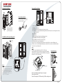
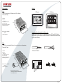
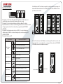
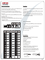
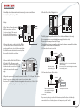
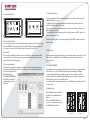
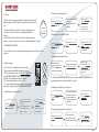
RK INSTRUCTION MANUAL
The design and specifications of this manual can be changed without notification to the user.
All copyright and interpretation right are reserved to Evervue.
INDEX
Features
System Capacity
Parts and Functions
Specifications
Maximum distance
Name Plate
Standard Installation
Installation with Expanding panel
Terminal Descriptions
DPS
Power Supply
Monitor
Door Station - ID Settings
Monitor - User Code Settings
Basic Instructions
Installation Instructions
Electric Door Strike/Magnetic Lock
Intercom Function
Setup Timing Options
Online Seach
Adding New User Cards/Key Fobs
Wiring Diagram 1/2
Wiring Diagram 3/4
Wiring Diagram 5/6
01
01
01
01
01
01
02
02
02
02
03
03
04
05
05
06
06
07
07
07
08
09
10
11
Specifications:
Features:
• 2-wire system (no polarity between door station and monitors);
• Centralized power supply for the entire system;
• Full anodize aluminum panel;
• SONY color CCD camera;
• Camera's angle is adjustable;
• Access control is optional (max.1000 ID cards);
• IP45 protection rate;
• Night view LED lights;
• Lighted name plate;
• Direct connect either an electric door strike or
a magnetic lock to Door Station;
• Direct connect an exit button to Door Station;
• Inner call between monitors;
• One monitor can be programmed as Guard unit.
CALL
Unlock Power output
Working Tempereature
12Vdc 300mA.
-4 F to 122 F
-20 C to 50 C
UNLOCK
IN-USE
2
CALL
UNLOCK
TALK/MON
IN-USE
2
Maximum distance:
CALL
UNLOCK
TALK/MON
IN-USE
Wire used
Maximum distance
between door station
and the last monitor of
the line.
Comment
CAT5 or CAT6
300 feet (100 meters)
Use 1 pair for each
conductor. Solder
the ends of the
pair together
18/2 speaker wire
(stranded, not
sheilded)
300 feet (100 meters)
14/2 speaker wire
(stranded, not
sheilded)
500 feet (150 meters)
Solder connections
together. Set voltage
between 25-27 volt
(can be adjusted on
the power supply)
2
CALL
UNLOCK
TALK/MON
IN-USE
System Capacity:
AC
DPS
• Maximum 4 Door Stations or,
3 Door Stations plus 2 CCTV Cameras* or,
2 Door Stations plus 4 CCTV Cameras* or,
1 Door Station plus 6 CCTV Cameras*.
• Maximum 32 apartments;
• Maximum 4 monitors per apartment.
PS5
2
*Need need to purchase a DCU module for every 2 cameras.
Parts and functions:
Name Plate:
Press down and shift right/left to open the name plate cover. Insert the
name paper, and then insert the name plate cover back to the panel.
Note that double button line panel can be opened from both directions,
and single button line can be opened only from the right side.
Camera Lens
CDS Sensor
Infrared LED
308 mm
298.5 mm
Camera Angle
adjustment
Microphone
24Vdc (supplied by PS-50 or PS-55).
11W in standby, 15W in working mode.
Sony color CCD, 420 lines;
Viewing angle is 85 degrees.
TALK/MON
2
Speaker
Power Supply
Power Consumption
Camera
Speaker Vol
adjustment
Da
Name plate
vid
Calo
Connection
Board
Call button
18 mm
123 mm
45 mm
114.5 mm
Page 01
Standard Installation:
L1
L1
L2
PA
PB
BUS
PA
L2
1
2
3
SET
JP-LK
123456
4
ON
CN-LK
1
2
3
m
5m
T/R T/R+
+12V
LK - (GND)
LK+(COM)
N.O.
EB+
EB -
RS-485
DMR11
Connection Board
Open the mounting box of the panel, use a
cross screw to adjust the view angle of the
camera before installation.
123456
ON
CN-LK
Camera Angle adjustment
298.5 mm
T/R T/R+
+12V
LK - (GND)
LK+(COM)
N.O.
EB+
EB -
RS-485
mm
SET
114.5
Terminal Descriptions:
PB
BUS
•
•
•
•
Ensure to properly seal
along the sides and the
top of the door station.
•
•
•
•
•
•
•
•
•
Installation with expanding panel
Jointer*2
+12V: 12 VDC power output.
LK-(GND): power ground.
LK+(COM): electronical load activation relay contact common.
NO.: Normally open contact (the default setting for this terminal is NO, but it can be configured to normally
closed contact NC.)
EB+: Exit button.
EB-: Exit button.
JP-LK: Jumper (refer to Electric Door Strike/Magnetic lock).
T/R-: USB-RS485 communication terminal negative.
T/R+: USB-RS485 communication terminal positive.
SET: DIP switches for system configurations.
PA: Press once to send the name list to Monitor; press and hold for 3 seconds to add Master card.
PB: Press once to search the Right line Monitor; press and hold for 3 seconds to search left line Monitor.
Bus (L1,L2) : non-poliarity bus line.
DPS
This unit is a power distributor for the PS-50 or PS-55 power
supply. It transfers the power from the power supply to the suitable
power for the non polarity bus. Note that the DPS must work together
with the PS-50 or PS-55 power supply.
Direct Wall Mounting
Stopper
ON
JP-LK
The double button line expantion panel can
L1
L2
1
2
3
SET
123456
+12V
LK - (GND)
LK+(COM)
N.O.
EB+
EB -
CN-LK
Note
RS-485
85mm
T/R T/R+
2.25 in
PA
PB
4 in
can only be connected to single button line
Door Station. Ensure to ro er se ot s es
n t e to o t e oor st t on
DIN Rail Mounting
n
5i
3.
only be connected to double button line Door
Station;thesinglebuttonlineexpantionpanel
Connect to Monitor
BUS
Connect to Door Station
Power input: 24Vdc (supplied by power supply)
Power output: 18Vdc
Power Consumption: 0.25W in standby, 0.5W in working mode
Page 02
Power Supply:
Monitor:
PS-50:
*The PS-50 supports up to 32 Monitors and 4 Door Stations;
*Universal AC input.
L: AC input
N: AC input
: Earth Ground
V- (or COM): DC power output
V+: DC power output
VADJ: Output voltage adjustment
LED: Working state indicator
P7 Monitor
Manual
Monitor
1
2
1.75 in
3
4
Memory
Playback
Monitor
Album
Intercom
P10 Monitor
Multimedia
Manual
Monitor
Monitor
Intercom
Multimedia
Close
User Setup
03/15/2011 Fri.10:12 AM
Memory
Playback
Album
User Setup
Close
03/15/2012 Fri.10:12
6.5 in
INPUT: 100-240V / L N GROUND
50/60HZ
OUTPUT: 24VDC,3A V- V+
RUI
LED
Connecting the Green Plug to the back of the monitor:
Strip the ends of the wires about 1/3”. If using stranded wire or CAT5, you MUST solder the
ends to ensure a good connection. DO NOT use wire nuts to connect the wires (wire nuts are
for power and solid wires.)
4 in
PS-55:
*The PS-55 is recommended if you have 2 or more monitors in each apartment;
*Universal AC input.
good
L: AC input
N: AC input
: Earth Ground
V- (or COM): DC power output
V+: DC power output
VADJ: Output voltage adjustment
LED: Working state indicator
wrong
well twisted and soldered
1.75 in
8 in
RUI
LED
Monitor
Connection Board
S1
ON
1 2 3 4 5 6
INPUT: 100-240V / L N GROUND
50/60HZ
OUTPUT: 24VDC,5A V- V+
BUS
4 in
DUAL INPUT VOLTAGE: 110/220V AC
SELECT PROPER VOLTAGE BY MOVING THE SWITCH
TO THE CORRECT POSITION.
Page 03
Door Station ID Settings:
ON(1)
ON 1 2 3 4 5 6
OFF(0)
=
=
ON
ON
*Dip Switches 1 and 2: For the Door Station ID setting. When multi Door Stations are
installed in the system, these two Dip Switches must be set correctly.
*Dip Switch 3: To select a Single Line Button or Double Line Button Door Station.
*Dip Switch 4: Button code selection. Set OFF if using default codes for each button. Set ON
if using programmed codes. Each code must be programmed by the DT CONFIG.
SOFTWARE.
*Dip Switch 5: Unlocking time quick selection. Set OFF for 1 second unlocking time default setting. Set ON for 5 seconds unlocking time; this can be changed by the DT
CONFIG. SOFTWARE.
*Dip Switch 6: Must be set OFF.
Function Descriptions
Dip Switches
1 2 3 4 5 6
ID = 0, set to the first Door Station.
ON
1 2 3 4 5 6
Dip Switches
1 and 2
Each call button of the Door Station is assigned to a speific apartment, and pressing a call
button will call the related monitor. The default User Code for each call button has been
pre-defined as shown below:
ID = 1, set to the second Door Station.
Bit-4=off
31
32
16
28
29
30
15
27
27
28
14
26
25
26
13
25
23
24
12
24
21
22
11
23
19
20
10
22
17
18
09
21
07
08
15
16
04
08
20
05
06
13
14
03
07
19
03
04
11
12
02
06
18
01
02
09
10
01
05
17
123456
Bit-4=on
123456
ON
ON
The User Code addresses of the Call Buttons can be changed if needed. You can also add a
cancel / exit button or an extra button for a security guard. Please refer to the DT-CONFIG.
SOFTWARE user manual for additional information.
ON
1 2 3 4 5 6
ID = 2, set to the third Door Station.
ON
1 2 3 4 5 6
ID = 3, set to the fourth Door Station.
ON
1 2 3 4 5 6
Dip Switches 3
Double Line Button.
ON
1 2 3 4 5 6
Single Line Button.
ON
1 2 3 4 5 6
Dip Switches 4
Set OFF if using defaut codes for each button.
ON
1 2 3 4 5 6
Set ON if using programmed codes.
ON
1 2 3 4 5 6
Dip Switches 5
Default setting, unlocking time = 1 second.
Cancel / exit button
ON
1 2 3 4 5 6
07
08
01
02
05
06
03
04
03
04
05 06
01
02
Guard Unit Button
07
08
Unlocking time = 5 seconds.(can be changed by software)
ON
1 2 3 4 5 6
Dip Switches 6
Working state
.
ON
1 2 3 4 5 6
Function reserved
.
ON
Page 04
Monitor - User Code Settings:
Slave address:
Every apartment must have an unique user code. There are a total of 6 Dip Switches in the
back of each monitor, and they must be confirgured correctly.
*Dip Switches 1 to 5: User Code Setting; There are a total of 32 different user codes.
*You can add a maximum of 4 monitors in each apartment, and they must be set with the
same user code.
The first monitor of the line should be programmed as MASTER, and the others should be
programmes as SLAVE.
*Dip Switch 6: Line terminal Switch, please note:
*If DAISY CHAIN connection used, the dip switch # 6 should be set ON only on the monitor
that is at the end of the line.
*If PARALLEL connection used, all monitors should have the dip switch # 6 set ON.
You can add a maximum of 4 monitors in each apartment, and they must be set with the
same User Code.
The first monitor of the line should be programmed as MASTER, and the others should be
programmed as SLAVE.
When the Door Station calls, all monitors will ring simultaneously, and only the master
monitor will show the video. To program the slave monitors to show the video, select the
“Installer Setup”, and enter the code 8006#.
Dip Switch
#6
ON(1)
ON 1 2 3 4 5 6
ON
Dip Switches
ON
=
User Code
Code=1
1 2 3 4 5 6
ON
Code=2
Code=3
Code=4
Code=5
Code=6
Code=7
Code=8
Code=9
1 2 3 4 5 6
ON
ON
ON
ON
ON
ON
ON
Code=10
ON
Code=14
ON
1 2 3 4 5 6
ON
1. From the Main Menu, press the ENTRYVUE logo located on the bottom left of the
screen;
2. Press and hold the screen for 3 seconds, then select “Installer Setup”,
3. Enter the proper code for MATER or SLAVE;
4. Press “#” to save the new setting;
5. Press “cancel” to exit out.
User Code
Code=23
ON
Code=24
ON
Code=25
1 2 3 4 5 6
Code=15
ON
Code=26
1 2 3 4 5 6
Code=16
ON
Code=27
1 2 3 4 5 6
Code=17
ON
Code=28
1 2 3 4 5 6
Code=18
ON
Code=29
1 2 3 4 5 6
Code=19
ON
Code=30
1 2 3 4 5 6
Code=20
ON
Code=31
Basic instructions:
1. Check the contents of your order. To be able to set up a system,
you must have at least the following:
* One Door station
* One Monitor
* Dps Box (Power distributor Box)
* Power Supply (PS-50 or PS-55)
2. Recommended wires are:
* 14 gauge 2 conductor stranded wire, not shielded (speaker wire).
* CAT5 ( MUST use a pair of wire for each conductor)
Strip the ends of the wires about 1/3”. If using stranded wire or CAT5,
solder the ends to ensure a good connection. Do Not use wire nuts to
connect wires (wire nuts are for power and solid wires).
1 2 3 4 5 6
Code=21
1 2 3 4 5 6
Code=11
Dip Switches
1 2 3 4 5 6
1 2 3 4 5 6
1 2 3 4 5 6
ON
Code=13
1 2 3 4 5 6
1 2 3 4 5 6
ON
ON
ON
1 2 3 4 5 6
Setting
Monitor at
the end of
the line.
MASTER / SLAVE PROGRAMMING:
1 2 3 4 5 6
1 2 3 4 5 6
1 2 3 4 5 6
ON
Code=12
1 2 3 4 5 6
1 2 3 4 5 6
ON
User Code
1 2 3 4 5 6
1 2 3 4 5 6
ON
ON
1 2 3 4 5 6
1 2 3 4 5 6
ON
Dip Switches
1 2 3 4 5 6
1 2 3 4 5 6
1 2 3 4 5 6
ON
ON
=
1 2 3 4 5 6
1 2 3 4 5 6
ON
ON
Setting
Monitor not at
the end of the
line.
1 2 3 4 5 6
1 2 3 4 5 6
ON
OFF(0)
Dip Switch
#6
ON
1 2 3 4 5 6
Code=22
Code=32
good
wrong
well twisted and soldered
Page 05
L2
RS-485
PA
PB
BUS
PA
PB
BUS
PA
PB
Connect to DPS
*The RK System is compatible with Electric Door Strikes and Magnetic Locks only;
*It is recommended to use an individual power supply for the door lock;
*Remove the black jumper from the JP-LK port;
*The default unlock type is normally open, but it can be changed to normally closed by the
DT-CONFIG. software under the Parameter tab.
5.1 Connection for power to unlock:
+
-
Cut this line
+12V
LK - (GND)
LK+(COM)
N.O.
EB+
EB -
+
POWER
SUPPLY
Remove the Jumper
Set to Normally Open.
1
2
3
JP_LK
4.3 Connect the Red Wire of the DPS Box to
the Positive (24V) of the power supply,
usually the V+ or the Red connection. The
black wire should connect to the V- (COM)
or the black connection of the power
supply.
L1 L2
SET
RS-485
SET
L1
1
2
3
1
2
3
123456
L1 L2
123456
JP-LK
4.2 Connect the wire to the right side of the DPS Box.
Then connect the other end of that same wire to the
green plug and then to the back of the monitor. Make
sure that these wires do not twist too much, and that
they are well isolated from each other.
1
2
3
ON
BUS
Exit Button
Connect to PC
T/R T/R+
+12V
LK - (GND)
LK+(COM)
N.O.
EB+
EB -
CN-LK
123456
ON
+12V
LK - (GND)
LK+(COM)
N.O.
EB EB+
+
DMR11
Connection Board
JP-LK
T/R T/R+
T/R T/R+
ON
CN-LK
4.Setup:
4.1 Door Station: Connect the wire to
the BUS connection on the Door
Station (no polarity). Then connect
the other end of that same wire to
the left connection on the DPS box.
+12V
LK - (GND)
LK+(COM)
N.O.
EB+
EB -
RS-485
5. Electric Door Strike / Magnetic Lock:
SET
3. If multiple door stations and monitors are used, you can connect them
in series (daisy chain) or in parallel.
DIPS
123456
ON
DIP SWITCH 5: Set OFF for 1 second unlocking time
(default setting).
In most cases, the 1 second unlocking time works best
for normally open locks.
5.2 Connection for power off to unlock:
4.4 Plug in the power supply: Connect the terminal L and N to 110 - 240V input. This can be
hardwird or a power cord plug can be connected to an electric outlet.
If you have a PS-55, make sure that the voltage switch in the unit is set to 110V or 220V
before turning ON (depending the country where you live).
+
-
Cut this line
+12V
LK - (GND)
LK+(COM)
N.O.
EB+
EB -
+
1
2
3
JP_LK
Remove the Jumper and set
to Normally Closed using the
DT-CONFIG. software
DIPS
123456
ON
DIPS-5: set to on,
unlocking time is 5 seconds.
5.3 No lock:
2
3
JP_LK
If you are not planning to use the Unlock Feature, and will not have a lock directly
connected to the Door Station, please set the Jumper to position 1 and 2.
1
Page 06
7. Setup Timing Options:
6.0 Intercom function:
1
2
3
4
Manual
Monitor
Monitor
Intercom
Multimedia
Memory
Playback
Album
User Setup
Close
1
2
Intercom
by Namelist
Inner Call
Direct Call
Guard Unit
3
07/26/2012 Fri.10:12 AM
4
Home
07/26/2012 Fri.10:12 AM
6.1 Direct Call Guard Unit:
You can assign one monitor to be the Guard Unit by programming on the Installer’s Setup.
Press the “ENTRYVUE” logo located on the bottom left of the main menu, press and hold
the screen for 3 seconds, select “Installer Setup”, and enter the code 8004#.
6.2 Inner Call:
The Inner call is available when multi monitors are installed in a single apartment. When
you select the “Inner call”, all monitors in the apartment will ring, and when a monitor is
answered, the others will stop ringing.
6.3 Intercom by Namelist:
This feature is for apartment to apartment calling. You can call a specific apartment by
selecting the apartment number or the name on the screen. A complete namelist of all
users can be uploaded to the
Door Station by the
DT-CONFIG. SOFTWARE, and
then the Door Station will
automatically send it to all
monitors.
* Pick-up waiting time: This is the call timing from the Door Station to the monitor. The
default setting is 30 seconds.
* Talking time: This is the open communication timing from the monitor to the Door
Station. The default setting is 90 seconds.
* Intercom time: This is the call timing from monitor to monitor (Intercom feature). The
default setting is 30 seconds.
* Monitoring time: An user can monitor the Door Station camera or a CCTV camera. The
defaut setting is 30 seconds.
*Note that the Timing Options can be changed by the DT-CONFIG. software under the
Parameter tab.
8. Online Search:
This function was designed for the purpose of searching for online monitors, and to check
if all monitors are working. There are 3 different ways to search for online monitors:
*Manually search
*ID tag
*DT-CONFIG SOFTWARE
When this function is on working mode, the Door Station will search every monitor with
User Codes from 1 to 32. If a monitor is found online and is working, the LED light
corresponding to that User Code will light up and 1-beep sound will be heard. If a
monitor is not found or malfunctioning, the LED light corresponding to that User Code
will not light up, and 3-beep sound will be heard.
You can interrupt the search at any time by pressing the PB button located in the back of
the door station.
8.1 Manual Search:
Press the PB button to search for the
monitors in the right Call Button’s
Column.
Press and hold the PB button for 3
seconds to search for the monitors in
the left Call Button’s Column.
31
32
31
32
29
30
29
30
27
28
27
28
25
26
25
26
23
24
23
24
21
22
21
22
19
20
19
20
17
18
17
18
07
08
15
16
07
08
15
16
05
06
13
14
05
06
13
14
03
04
11
12
03
04
11
12
01
02
09
10
01
02
09
10
PB button
Online search range
PB button for 3 seconds
Online search range
Page 07
9.2 Deleting User Cards/Key Fobs:
8.2 ID Tag
The Door Station comes standard with a Online Search Card labeled
with the number 16666666, which is designed for the online search
only.
Show the ID card in front of the Door Station’s Card Reader for 3
seconds to search for the monitors in the right Call Button’s
Column.
Show the ID card in front of the Door Station’s Card Reader twice
within 3 seconds to search for the monitors in the left Call Button’s Column.
Show the MASTER CARD
DELETE card in standby.
Note. sounded Di~,Di
16666666
Show the cards to be deleted,
one by one.
Note. Long beep if deleted
successfully
Show the MASTER
CARD DELETE card
again to exit.
It will exit if no card
is showed within 15s.
9.3 Deleting ALL User Cards/Key Fobs:
Show the MASTER CARD
DELETE card in standby.
Note. sounded Di~,Di
8.3 DT-CONFIG. SOFTWARE:
Show theMASTER CARD
ADD card to run format
operation.
Press the “Online Search” button from the Debug tab to start searching for online
monitors.
Show the MASTER CARD
ADD card again within
Format operation.
9.4 Authorizing New Master Cards:
9. ID Card Settings:
* Up to 1000 user cards/key fobs can be registered.
* Easy management with LED state and Sound hint.
* There are two master cards, one MASTER CARD ADD and
one MASTER CARD DELETE. When adding a new Master
Card, the old one will be automatically deleted.
* The card reading distance is about 1 to 2 in.
* You can manually add and delete cards, or you can easily
manage the cards by using the DT-CONFIG. SOFTWARE.
MASTER
CARD
ADD
MASTER
CARD
DELETE
When Door Station is in
standby, press PA button and
hold for 3 seconds to get into
the master card manage state.
9.5 Adding User Cards/Key Fobs by Room:
Show the MASTER CARD
ADD card in standby
Showthecardstobeadded,
one by one.
Note. Long beep if added
successefully, two long
beeps if repeated.
show the card to be
authorized as MASTER
CARD DELETE , and
then the Reader willexit out
automatically.
*To authorize a MASTER CARD DELETE, ensure to show the MASTER CARD ADD first. The
programming must be completed within 10 seconds.
9.1 Adding new User Cards/Key Fobs:
Show the MASTER CARD
ADD card in standby.
Note. sounded Di~,Di
Show the card to be autorized
as MASTER CARD ADD ,
you will hear a long beep*1
Show the MASTER
CARD ADD card again to
exit.
It will exit if no card is
showed within 15s.
Press a certain button on the
Door Station, then show the
cards to be assigned to this
Room. Repeat the same step
untill finished.
Show the MASTER
CARD ADD card again to
9.6 Deleting User Cards/Key Fobs by Room:
Show the MASTER CARD
DELETE card in standby
Press the button that the
cards belong to on the Door
Station.(all cards will be deleted)
Show the MASTER
CARD DELETE card
Page 08
10. System Wiring Diagram:
Example 2:
Example 1:
ON
ON
CALL
ON
CALL
UNLOCK
1 2 3 4 56
IN-USE
UNLOCK
TALK/MON
CALL
TALK/MON
IN-USE
UNLOCK
TALK/MON
1 2 3 4 5 6
IN-USE
1 2 3 4 5 6
Code6
Code 3
ON
CALL
UNLOCK
Code5
ON
CALL
TALK/MON
IN-USE
1 2 3 4 5 6
Code2
Code3
ON
TALK/MON
IN-USE
1 2 3 4 5 6
CALL
CALL
1 2 3 4 5 6
CALL
UNLOCK
TALK/MON
IN-USE
Code4
ON
UNLOCK
ON
UNLOCK
TALK/MON
1 2 3 4 5 6
ON
CALL
UNLOCK
UNLOCK
TALK/MON
TALK/MON
IN-USE
IN-USE
1 2 3 4 5 6
1 2 3 4 5 6
IN-USE
Code2
Code1
Code1
POWER SUPPLY
PS-50/PS55
DPS
Power
Supply
DPS
POWER SUPPLY
PS-50/PS55
Power
Supply
ID=0
123456
ON
ID=0
LOCK
123456
LOCK
ON
Page 09
Example 3:
ON
Example 4:
ON
CALL
UNLOCK
TALK/MON
IN-USE
IN-USE
1 2 3 4 5 6
1 2 3 4 5 6
Code=4
Code=3
ON
IN-USE
1 2 3 4 5 6
Code=3
CALL
UNLOCK
TALK/MON
IN-USE
IN-USE
ON
1 2 3 4 5 6
Code=2
CALL
UNLOCK
TALK/MON
IN-USE
Code=4
TALK/MON
1 2 3 4 5 6
ON
CALL
UNLOCK
TALK/MON
1 2 3 4 5 6
ON
CALL
UNLOCK
ON
CALL
UNLOCK
TALK/MON
Code=1
DPS
ON
CALL
UNLOCK
CALL
UNLOCK
TALK/MON
TALK/MON
IN-USE
IN-USE
1 2 3 4 5 6
1 2 3 4 5 6
Code=2
Code=1
PS5
ID=1
123456
ON
ON
123456
DCU
Power
Supply
POWER SUPPLY
PS-50/PS55
Power
Supply
ID=0
ID=2
123456
123456
ON
ON
LOCK
LOCK
Power
Supply
Power
Supply
ID=1
Power
Supply
ID=3
123456
ID=0
123456
ON
LOCK
DPS
ON
LOCK
LOCK
123456
ON
Page 10
Example 5:
Example 6:
ON
CALL
UNLOCK
TALK/MON
IN-USE
IN-USE
1 2 3 4 5 6
1 2 3 4 5 6
Code=4
1 2 3 4 5 6
Code=3
ON
CALL
UNLOCK
TALK/MON
IN-USE
Code=3
TPC
ON
CALL
UNLOCK
TALK/MON
OUT IN
ON
1 2 3 4 5 6
to telephone network
ON
CALL
UNLOCK
TALK/MON
ON
ON
ON
CALL
UNLOCK
Code=2
CALL
UNLOCK
TALK/MON
TALK/MON
IN-USE
IN-USE
1 2 3 4 5 6
1 2 3 4 5 6
Code=2
Code=1
OUT IN
1 2 3 4 5 6
TPC
IN-USE
1 2 3 4 5 6
to telephone network
ON
OUT IN
Code=1
TPC
ON
1 2 3 4 5 6
1 2 3 4 5 6
to telephone network
1 2 3 4 5 6
POWER SUPPLY
PS-50/PS55
DPS
ON
ID=1
DIP6 = ON
123456
ON
TPS
ON
123456
DCU
DPS
POWER SUPPLY
PS-50/PS55
Power
Supply
ID=0
LOCK
123456
ON
Power
Supply
ID=0
LOCK
123456
ON
Page 11