1
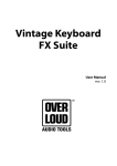
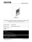
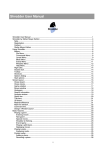
CAP FRAC 03 and 05 AIR COOLED CHILLER 1 & 3 PHASE MADE IN USA COMMERCIAL AIRE PRODUCTS CAP RECIP CHILLER FRAC-03/05, I/ O Instructions 2014. Page1 501 Terminal Road, Fort Worth TX 76106 Tel: 817-624-0820 TABLE OF CONTENTS INTRODUCTION........................................................................................................... 3 GENERAL DESCRIPTION......................................................................................... 3 DIMENSIONS.............................................................................................................. 6 INSTALLATION.......................................................................................................... Transport ....................................................................................................... Lifting.............................................................................................................. Lay-out and installation requirements........................................................... Location......................................................................................................... Space Requirements………………………………………………………………. Acoustic Protection ....................................................................................... WARRANTY…………………………………………………………………………………. 8 8 9 9 9 10 10 11 TYIPICAL PIPING LAYOUT FOR A SINGLE CHILLER………………………………… Typical piping for two chillers in parallel ………………………………………… 12 13 CONTROL PANEL.................................................................................................... Nomenclature ……………………………………………………………………. Wiring Diagram ………………………….…………………………………………. 15 14 16 START UP …………………………………………………………………………………… 26 SYSTEM MAINTENANCE......................................................................................... General........................................................................................................ Controls ………………….…………………………......................................... Compressor Maintenance ……………................................................................. Filter Dryer………………………………………………………………………... Refrigerant sight glass.................................................................................. Thermostatic Expansion Valve…………………………………………………… High Condenser pressure protection………………………………………………… Condenser………………………………………………………………………… Coaxial Heat Exchanger Evaporator……………………………………………….. Adding Refrigerant…………………………………………………………………. Service and replacing parts……………………………………………………….. 17 18 21 22 22 23 23 23 24 24 25 25 TROUBLESHOOTING - REPAIRS............................................................................ List of the most common problems ............................................................... Inspection recommended for units with reciprocating compressors.............. 26 26 28 START UP CHECK LIST......................................................................................... 29 MAINTENANCE LOG………………………………………………………………………. 30 COMMERCIAL AIRE PRODUCTS CAP RECIP CHILLER FRAC-03/05, I/ O Instructions 2014. Page2 501 Terminal Road, Fort Worth TX 76106 Tel: 817-624-0820 INTRODUCTION You must read and be familiar with this operating manual prior to chiller startup. Please closely follow the instructions. We would like to stress the importance of training with respect to the correct operation of the chiller. Please consult CAP on the options available for training. It is important that this manual be stored in a permanent location in the vicinity of the chiller. Important general instruction Danger of Injury or damage to the chiller This manual contains important instructions regarding the startup of the chiller. It also includes important instructions to prevent personal injury and damage to the machine during operation. Furthermore, in order to promote fault-free operation of the chiller, maintenance information has been included. Please do not hesitate to contact one of our employees should you require further information on specific chiller subjects. Order related documentation to be forwarded under separate cover. This documentation consists of: - Installation and Operation manual for the chiller - Operating manual for control system. - Wiring diagram. - Unit detail is given on unit nameplate. The data published in this manual is based on the most recent information available. It is supplied conditional to later modifications. We reserve the right to modify the construction and/or design of our chillers at any time, without prior notification or obligation to adapt previously supplied equipment. Any work on the Chiller should be carried out by trained and/or licensed competent technicians. The following risks are present on the unit: - Risk of electrical shock - Risk of injury from rotating parts - Risk of injury from sharp edges and heavy weight - Risk of injury from high pressure gas - Risk of injury from high and low temperatures components. It is expected that all work on equipment be carried out in accordance with all local standards and codes. It is expected that all work will be carried out with good working practices. General Description: Units are leak and pressure tested at 500 psig high side, 250 psig low sides, then evacuated and charged. All Air-cooled Model FRAC chillers are factory tested to confirm operation prior to shipment. Units ship with full operating charge of oil and refrigerant. Unit panels, structural elements and control boxes are constructed of galvanized steel and mounted on a structural steel base. Unit panels and control boxes are finished with baked-on powder paint, and the structural base is galvanized. All paint meets the requirement for outdoor equipment. COMMERCIAL AIRE PRODUCTS CAP RECIP CHILLER FRAC-03/05, I/ O Instructions 2014. Page3 501 Terminal Road, Fort Worth TX 76106 Tel: 817-624-0820 Standard Features CAP’s horizontal air discharge chiller model “FRAC-03 & 05” are cost efficient package Chillers, environmentally friendly, CFC Free, with R-410A, non-ozone depleting, using state-of-the-art recip compressors, high efficiency, counter flow coaxial evaporator proven for durability, efficiency and performance, and copper tube aluminum fins condenser; water pump and controls installed in the unit making this unit one of the most cost efficient for small commercial and residential applications. Many factory mounted options save expensive field labor and material, resulting in lower first and operating costs. Water Pump The chiller water pump is carefully selected to fit most residential and small commercial applications, is fully installed, piped and wired to the control box and piped to chilled water system to save expensive field installation costs. Condenser Air Fan Unit is also designed to start and operate in higher ambient conditions, up to 115 degrees ºF. The large surface, low speed, propeller fan for horizontal air flow fan is statically and dynamically balanced and operates at low tip speeds for low vibration and low sound levels. Fan Guard: Fan guard is chrome-plated to meet OSHA requirements. Refrigerant Circuit Each unit has one refrigerant circuit, with one Reciprocant compressor. The refrigerant circuit includes compressor filter dryer, liquid line sight glass, charging port and one expansion valve. Power Connection Unit is provided with single-point electrical power connection. Field wiring connection point will be at the starter panel. Voltage Options: A - 208/230/1/60 B – 208/230/3/60 C – 460/3/60 COMMERCIAL AIRE PRODUCTS CAP RECIP CHILLER FRAC-03/05, I/ O Instructions 2014. Page4 501 Terminal Road, Fort Worth TX 76106 Tel: 817-624-0820 Bristol Compressors Bristol Compressors are the machine of choice in a wide range of applications that demand efficiency and reliability with low sound output. This time proven technology has been enhanced with continuous improvements and innovation in materials, machining, assembly techniques, and quality assurance. Bristol Compressors are durable, robust, and are used worldwide by leading manufacturers in applications across virtually every HVAC-R market segment Chiller/Evaporator: Coaxial counter flow high efficiency evaporators are UL listed. The evaporator has a uniquely built direct expansion distributor designed specifically for chillers. Refrigerant Piping: Refrigerant circuit includes: Liquid charging connection • Sealed Filter drier • Suction service connection • Sight glass • Expansion valve Control Center: All power, operating and safety controls are mounted in a NEMA 3R enclosure. • Single point electrical terminal block • Compressors Contactor • Fan Motor Relay • High pressure switch with manual reset • Low pressure switch with auto reset • Chiller digital controller Factory Mounted Available Options: • Variable Speed compressor • Straight cooling or Heat pump • Sound enclosure • Heat recovery with factory mounted hot water pump • Choice of flanges or grooved connections • Indicating lights Low ambient kit COMMERCIAL AIRE PRODUCTS CAP RECIP CHILLER FRAC-03/05, I/ O Instructions 2014. Page5 501 Terminal Road, Fort Worth TX 76106 Tel: 817-624-0820 UNIT DIMESIONS FRAC-03 and 05 FRAC 03 and 05 Capacity CAPACITY FRAC Size Tons. 03 3.4 Compressor Number of Kw Number of Compressors 4.5 FL EFF IPLV 1 Tons FSACS (Kw) 4.5 Fans Fans 1 (Kw) EER 0.34 9.92 COP Kw EER 12.45 05 5.6 6.2 6.2 1 1 0.34 9.75 12.35 This unit is rated in accordance with AHRI-550/590 standard rating conditions; options are not included in these ratings EER Energy Efficiency Ratio COP Coefficient of Performance IPLV Integrated Part Load Value FRAC 03 and 05 Dimensions & Weights FRAC Weight Dry Length Width Height Shipping Weight Shipping Volume Size LB Kg Inches mm Inches mm Inches mm lb Kg Cu ft Cu mts 03 490 222.7 48.00 1219 28.146 715 48.00 1219 521 236.8 40 1.13 05 525 238.6 48.00 1219 28.146 715 48.00 1219 556 252.8 40 1.13 COMMERCIAL AIRE PRODUCTS Aguar CAP RECIP CHILLER FRAC-03/05, I/ O Instructions 2014. Page6 501 Terminal Road, Fort Worth TX 76106 Tel: 817-624-0820 FSAC 03, and 05 ELECTRICAL DATA UNIT FSAC COMPRESSOR DATA FAN DATA PUMP DATA UNIT VOLTAGE BREAKER SIZE SIZE RLA LRA FLA RPM FLA SIZE RLA LRA FLA RPM FLA 03-A 19.2 85 1.03 3450 3.8 3450 15.0 60 208/230/1/60 30 48 03-B 8.5 48 1.03 3450 3.8 3450 15.0 60 208/230/3/60 20 30 05-A 29.7 110 1.03 3450 3.8 3450 15.0 60 208/230/1/60 40 70 05-B 14.8 88 1.03 3450 3.8 3450 15.0 60 208/230/3/60 30 50 05-C 7.6 44 1.03 3450 3.8 3450 15.0 60 460/3/60 20 25 FRAC 03 COOLING PERFORMANCE DATA LWT ENTERING AIR TEMPERATURE ºF 85 º F TONS MBTU 35 2.60 40 95 º F GPM TONS MBTU 31.14 2.52 2.67 32.04 42 2.75 32.96 45 2.83 33.91 46 2.91 48 100 º F TONS MBTU 30.27 2.45 2.60 31.14 2.67 32.04 2.75 32.96 34.89 2.83 2.99 35.90 50 3.08 55 3.17 60 3.26 110 º F TONS MBTU 29.42 2.38 28.60 2.52 30.27 2.45 29.42 2.60 31.14 2.52 30.27 2.67 32.04 2.60 31.14 33.91 2.75 32.96 2.67 32.04 2.91 34.89 2.83 33.91 2.75 32.96 36.93 2.99 35.90 2.91 34.89 2.83 33.91 37.99 3.08 36.93 2.99 35.90 2.91 34.89 39.09 3.17 37.99 3.08 36.93 2.99 35.90 7.2 GPM 7.2 GPM 7.2 GPM 7.2 FRAC 05 COOLING PERFORMANCE DATA LWT ENTERING AIR TEMPERATURE ºF 85 º F 95 º F GPM 100 º F TONS MBTU TONS MBTU TONS MBTU TONS MBTU 35 4.75 57.00 4.62 55.40 4.49 53.85 4.36 52.34 40 5.45 65.40 5.30 63.57 5.15 61.79 5.00 60.06 42 6.02 72.24 5.85 70.22 5.69 68.25 5.53 66.34 45 6.35 76.2 6.17 74.07 6.00 71.99 5.83 69.98 46 6.49 77.88 6.31 75.70 6.13 73.58 5.96 71.52 48 6.95 83.4 6.76 81.06 6.57 78.79 6.38 76.59 50 7.45 89.4 7.24 86.90 7.04 84.46 6.84 82.10 55 7.98 95.76 7.76 93.08 7.54 90.47 7.33 87.94 60 8.36 100.32 8.13 97.51 7.90 94.78 7.68 92.13 14.4 COMMERCIAL AIRE PRODUCTS GPM 110 º F 14.4 GPM 14.4 GPM 14.4 CAP RECIP CHILLER FRAC-03/05, I/ O Instructions 2014. Page7 501 Terminal Road, Fort Worth TX 76106 Tel: 817-624-0820 Installation Before operating equipment please check the installation and operating instructions. Warning Installation and maintenance are to be performed only by qualified personnel who are familiar with local codes and regulations, and who are experienced with this type of equipment. Do not install the unit in places that could be considered dangerous for maintenance operations. Transport It is necessary to stabilize the unit during transportation. Therefore the unit is supplied with a transversal wooden beam placed on the unit base that must to be removed at final destination. In case the unit has to be moved again, a similar solution is necessary. Handling and lifting Care should be taken to avoid rough handling or shock due to dropping. Do not move the unit using anything other than the base. When it is necessary to lift the unit suitable holes are provided in unit base to arrange spreader bars and cables to prevent damage to the condenser coils or cabinet. COMMERCIAL AIRE PRODUCTS CAP RECIP CHILLER FRAC-03/05, I/ O Instructions 2014. Page8 501 Terminal Road, Fort Worth TX 76106 Tel: 817-624-0820 Location The CAP FRAC units are designed for outside installation on roofs, floors or below ground level on condition that the area is free from obstructions for the passage of condenser air. The unit should be positioned on solid foundations and perfectly level; in the case of installation on roofs or floors, it may be advisable to arrange the use of suitable weight distribution beams. When the units are installed on the ground, a concrete base at least 12” wider and longer than the unit’s footprint should be laid. This base should withstand the unit weight mentioned in the technical data table. When the units are positioned in areas which are easily accessible by persons or animals, it is advisable to protect the condenser coils and, when necessary, also protect the evaporator area as applicable. To obtain the best performance the location must follow precautions listed: · Avoid air flow recirculation. · Take care that obstacle do not obstruct air flow. · Free air flow is required to ensure the right air entry and discharge. · To reduce noise and vibration proper floor support is required. · To avoid dirty condenser coils dirty avoid dusty locations. · Chiller water must be clean and free of oil and rust. If necessary a water filter and treatment should be installed. Space requirements COMMERCIAL AIRE PRODUCTS CAP RECIP CHILLER FRAC-03/05, I/ O Instructions 2014. Page9 501 Terminal Road, Fort Worth TX 76106 Tel: 817-624-0820 It is recommended to have at least 4 feet between the two chillers and at least 3 feet between any exterior walls that can obstruct the air flow through the coils. It is not acceptable to install any kind of roof over the chillers. The “FRAC” units are air-cooled; hence it is important to observe the minimum distances which guarantee the best ventilation of the condenser coils. Limitations of space reducing the air flow could cause significant reductions in cooling capacity and an increase in electricity consumption. To determine unit placement, careful consideration must be given to assure sufficient air flow across the condenser heat transfer surface. To achieve the best performance the following must be avoided, warm air recirculation and coil starvation. Both of these conditions cause an increase in condensing pressures that cause reductions in unit efficiency and capacity. Each side of the unit must be accessible after installation for periodic service. The minimum clearance on each side of the unit should be enough to walk around the unit. The compressor and evaporator side should have enough space to replace the compressor. Horizontal condenser air discharge must be unobstructed or the unit will have its capacity and efficiency significantly reduced. If the units are positioned in places surrounded by walls or obstacles of the same height as the units, the units should be at least 36” from obstacles. In the event the obstacles are higher than the units, the units should be at least 48” from the obstacle. Units installed closer than the minimum recommended distance to a wall or other vertical riser may experience a combination of coil starvation and warm air recirculation, thus causing reduction in unit capacity and efficiency reductions. Once again, the controls will allow the chiller to stay on line, producing the maximum available capacity, even at less than recommended lateral clearances. When two or more units are positioned side by side it is recommended that the condenser coils be at least 48” from one another. For other installation recommendations, consult CAP technicians. Acoustic protection The low noise level of the “FRAC” unit meets the most restrictive regulations. When the noise level must meet special requirements to the support base apply appropriate vibration-insulator devices, vibration-insulator mounts on the water piping and electrical connections. COMMERCIAL AIRE PRODUCTS CAP RECIP CHILLER FRAC-03/05, I/ O Instructions 2014. Page10 501 Terminal Road, Fort Worth TX 76106 Tel: 817-624-0820 WARRANTY The warranty of the chillers is subject to the warranty definitions as agreed upon in the order. All parts have one year warranty from the date of shipment against manufacturing defects and it is expected that the design and installation of the unit utilizes good working practices. The warranty will be legally void if: - Service and maintenance have not been executed in accordance with the CAP instructions; repairs have not been carried out by CAP personnel or have been implemented without prior written permission by CAP. - Modifications have been made to the equipment without prior written permission by CAP. - Settings and protections have been modified without prior written permission by CAP. - Non-original or other than the prescribed refrigerants or lubricants is used. - The equipment has not been installed and/or connected in accordance with the installation instructions. - The equipment is being used improperly, incorrectly, negligently or not in accordance with its nature and/or purpose. - A flow switch protection device is not installed or disabled the factory installed one. - An appropriate strainer and water treatment is not installed close to the water inlet of the chiller. Under these circumstances CAP is indemnified from any product liability claims from third parties. In the event of a warranty claim the machine serial number and CAP order number must be quoted. The above limitations shall inure to the benefit of CAP suppliers and sub-contractors. The above limitation on consequential damage shall not apply to injuries to persons in the case of consumer goods. Some states do not allow the exclusion or limitation of liability for consequential, or incidental damages, or for strict liability in tort, so the above exclusions and limitations may not apply. CAP does not assume or authorize any person to assume for CAP any other liability for the sale of CAP products. This warranty gives you specific legal rights. You may also have other rights which vary from state to state. The above warranty applies with respect to parts only and not labor. Accordingly, subject to the conditions and limitations set forth herein, the above warrant entitles the Customer only to receive a repaired or replacement part and the installation labor is not covered. However, under certain circumstances, CAP will provide labor services to repair a Product or install repaired or replacement parts at its designated repair facilities, or at its option, compensate its authorized dealers and authorized contractors at CAP’s standard fixed rates then in effect (irrespective of charges actually imposed and time actually expended) to provide such services. COMMERCIAL AIRE PRODUCTS CAP RECIP CHILLER FRAC-03/05, I/ O Instructions 2014. Page11 501 Terminal Road, Fort Worth TX 76106 Tel: 817-624-0820 Typical Piping for a Single Chiller, Single Pipe Installation This layout is not intended to be a design and is placed just to give an idea of the typical piping in a single chiller installation system. CAP assumes no responsibility for any omission or errors in the drawing. COMMERCIAL AIRE PRODUCTS CAP RECIP CHILLER FRAC-03/05, I/ O Instructions 2014. Page12 501 Terminal Road, Fort Worth TX 76106 Tel: 817-624-0820 Minimum water content The minimum volume of the chilled water circuit must be calculated with the following formula. If necessary, install a storage tank. Proper operation of regulating and safety devices can only be ensured if the volume of water is sufficient. WATER RANGE Vt = Minimum water volume of the installation in Gals. Q = Chiller cooling capacity in TR N = Number of capacity control steps available in the unit Dt = maximum acceptable temperature rise (Dt = 10°F for an air conditioning application) Vt = (167xQ) / (NxDt +18xN) The minimum water volume for a 5 ton chiller is 30 GALS The minimum water volume for a 3 ton chiller is 28 GALS This formula is only applicable for air-conditioning installation, and is only a rule of thumb and must not be used for process cooling where particular temperature stability is required. If the calculated volume in the system, adding the pipe volume with the chiller and AHU water volume is less than the minimum calculated, the storage tank has to be sized to cover the difference. If Vt is less than the actual calculated volume, no tank is necessary, but if Vt is a higher volume, then you must add a storage tank with the difference in the volume or bigger to assure the proper operation of the system; THE TANK SHOULD BE INSTALLED TO THE RETURN LINE OF THE CHILLER TO ALLOW MORE STABLE CHILLER OPERATION. TIPICAL STORAGE TANK COMMERCIAL AIRE PRODUCTS CAP RECIP CHILLER FRAC-03/05, I/ O Instructions 2014. Page13 501 Terminal Road, Fort Worth TX 76106 Tel: 817-624-0820 TYPICAL PIPING FOR TWO CHILLERS IN PARALEL primary-secondary circuits This layout is not intended to be a design and is placed just to give an idea of the typical piping in a parallel installation system. CAP assumes no responsibility for any omission or errors in the drawing. COMMERCIAL AIRE PRODUCTS CAP RECIP CHILLER FRAC-03/05, I/ O Instructions 2014. Page14 501 Terminal Road, Fort Worth TX 76106 Tel: 817-624-0820 CAP CHILLER DESCRIPTION MODEL NUMBER NOMENCLATURE F R A C REF COMPR TYPE UNIT - 05 A CAPACITY VOLT REFRIGERANT TYPE F R-410A M NU-22 B R-134A X SPECIAL COMPRESSOR TYPE S SCROLL R RECIP W SCREW CONDENSER TYPE A AIR COOLED UNIT TYPE C CHILLER UNIT CAPACITY (TON) 03 3 TON (36,000 BTUH NOMINAL) 05 5TON (60,000 BTUH NOMINAL) UNIT VOLTAGE A 208/230/1/60 B 208/230/3/60 C 460/3/60 D 380/3/50 E 575/3/60 COMMERCIAL AIRE PRODUCTS CAP RECIP CHILLER FRAC-03/05, I/ O Instructions 2014. Page15 501 Terminal Road, Fort Worth TX 76106 Tel: 817-624-0820 Wiring Diagram for FRAC 05 A, 208/230/1/60 Wiring Diagram for FRAC 05 B, 208/230/3/60 COMMERCIAL AIRE PRODUCTS CAP RECIP CHILLER FRAC-03/05, I/ O Instructions 2014. Page16 501 Terminal Road, Fort Worth TX 76106 Tel: 817-624-0820 Standard controls 1. INTRODUCTION Flow switch A flow switch is factory installed on the evaporator water inlet to enable detection of water flow through the heat exchanger before the unit is started up. This will protect the compressors against any eventual liquid slugging during the starting phase and prevent accidental ice formation in the evaporator if the flow of water is interrupted. If the Flow switch is by passed the warranty will be voided. The normally closed contact can be used as lack of flow alarm circuit. Warranty is void if a flow detection device is bypassed or disconnected from the CAP control panel. Strainer A strainer with a minimum of 40 meshes must be installed within 10 ft (3 m) of the heat exchanger fluid inlet to prevent debris from clogging the heat exchanger. This strainer is required and is available as an accessory. Safety Precautions Precautions for Installation: Never install the product in the environment beyond the one specified in the brochure and user manual, such as high temperature, humidity, dust, corrosive gas, vibration, impact condition resulting in the risk of inductive electricity, fire and error operation. Please comply with the installation instruction in the user manual to avoid damage or operation error. Pay close attention to avoid cable or conductor parts falling into the digital controller to prevent fire or electrical fault. Precautions for Wiring: Connect Class 3 grounding in accordance with the local Electricity Engineering Regulations. Apply the rated power supply and specified cables. Incorrect power supply could result in damage to the unit. The wiring shall be carried out by the certified electrician pursuant to the provisions set forth in the local Electricity Engineering Regulations. Precautions for Operation: When the power is on, never contact the terminal to avoid short circuit. It is recommended to add safety protection such as an emergency stop and external protection to prevent the controller from electrical damage. Run the controller after safety confirmation. Error operation will result in mechanical damage. Please pay attention to the power linkage procedure. Wrong process flow would lead to mechanical damage or other hazards. COMMERCIAL AIRE PRODUCTS CAP RECIP CHILLER FRAC-03/05, I/ O Instructions 2014. Page17 501 Terminal Road, Fort Worth TX 76106 Tel: 817-624-0820 1 General The Carel Chiller Control System is a micro-processor based controller which provides all control, protection and self diagnostic features for a chiller system with simplified wiring and an easy to use control panel. The air conditioner can use either hermetic Scroll or recip. or semi-hermetic type compressor(s). The condenser side can be up to 2 refrigerating circuits with 2 compressors per circuit. controller consists of Main control board 1 temperature sensor - water out, with standard 6 feet length. Low pressure switches High pressure switches The microprocessor controller is factory preprogrammed and all the factory settings are password protected. 1. USER INTERFACE 1- Screen The screen shows 3 digits, with a decimal point between -99.9 y 99.9. Out of this value range, the value will be shown without the decimal point but, internally will operate considering the decimal point. In normal operation, the screen value will show the sensor B1 temperature Reading that correspond to the return water temperature. (Heat exchanger entering water) 2- Screen symbols Figure 1.aShows the screen symbols, the keyboard and the meanings. Symbol Color LED on meaning LED off meaning 1; 2 Amber Compressor 1 or 2 on needs to start 1; 3 Amber Compressor 3 on needs to start A Amber At least 1 compressor ON B Amber Water pump ON needs to start COMMERCIAL AIRE PRODUCTS CAP RECIP CHILLER FRAC-03/05, I/ O Instructions 2014. Page18 501 Terminal Road, Fort Worth TX 76106 Tel: 817-624-0820 C D E F G H I Amber condenser fan ON Amber defrost cycle ON Amber Heater ON Red Active alarm Amber Heat pump cycle ON Amber Cooling Cycle ON Load preprogrammed values If some alarms are on Direct Access to parameters Go to the desire parameter and adjust it Password protected parameters Select an upper value Start up the controller Select a lower value L I+L J K needs to start needs to start needs to start Push to start Push once Push for 5 seconds Push once Push and hold Push and hold once Press and hold for 5 sec Push once 3- Programming & saving parameters The temperature settings are based on return temperature and are preprogrammed to start the first circuit at 56ºF and stop at 46ºF and the second circuit will start at 58ºF and stop at 48ºF If you want to modify these settings, follow the instructions to change and save. a- Programming user password is 22 b- Press and hold the the screen. & at the same time until you see 00 and two ** in c- Push up arrow until reach 22 on the screen, then push twice d- Push the Arrow up until reach “c” push and c01 will appear on the screen. e- Press the down arrow until c03 appears on the screen. f- Press the button. This is the time delay in seconds, between two starts of the same compressor. Use the up or down arrows to change this setting g- Press the button when done. The c03 will arrear on the screen. h- Use the down arrow until c06 appears on the screen if you want to change the startup time delay or press the button to save and exit. i- The time delay at startup is at c06. To change the time in seconds you will press the button when the c06 is displayed on the screen. j- Press the button and the current delay time in seconds will appear. k- Press the up or down arrows to change the setpoint. l- Press the button when done, the press the “ COMMERCIAL AIRE PRODUCTS button to save and exit. CAP RECIP CHILLER FRAC-03/05, I/ O Instructions 2014. Page19 501 Terminal Road, Fort Worth TX 76106 Tel: 817-624-0820 Changing the compressor time delay m- Programming user password is 22 n- Press and hold the the screen. & at the same time until you see 00 and two ** in o- Push up arrow until reach 22 on the screen, then push twice p- Push the Arrow up until reach “c” push SEL and c01 will appear on the screen. q- Press the down arrow until c03 appears on the screen. r- Press the button. This is the time delay in seconds, between two starts of the same compressor. Use the up or down arrows to change this setting s- Press the button when done. The c03 will arrear on the screen. t- Use the down arrow until c06 appears on the screen if you want to change the startup time delay or press the button to save and exit. u- The time delay at startup is at c06. To change the time in seconds you will press the button when the c06 is displayed on the screen. v- Press the button and the current delay time in seconds will appear. w- Press the up or down arrows to change the setpoint. x- Press the button when done, the press the button to save and exit. Note: a. The modified parameters without confirmation using the will automatically go back to the previous value. b. If you fail to do control operations in 60 seconds, the control will automatically go out of the programming mode and all the changes not saved will be cancelled. COMMERCIAL AIRE PRODUCTS CAP RECIP CHILLER FRAC-03/05, I/ O Instructions 2014. Page20 501 Terminal Road, Fort Worth TX 76106 Tel: 817-624-0820 TABLE OF ALARMS Alarm Display HP1 HP2 LP1 LP2 TP tC1 tC2 LA FL FLb E1 E2 E3 E4 E5 E6 E7 E8 Hc1-4 EPr EPb ESP EL1-2 dF1-2 d1-2 A1 A2 Ht Lt ELS EHS Ed1 Ed2 ᶙC2 ᶙC2 Alarm Descritpion Controller Expansion High Pressure Alarm * High Pressure Alarm * Low Pressure Alarm Low Pressure Alarm * General Overload * * Circuit 1 Overload * Circuit 1 Overload * Advise * Flow Alarm * Backup Pump Alarm * * Probe B1 Alarm * Probe B2 Alarm * Probe B3 Alarm * Probe B4 Alarm * Probe B5 Alarm * Probe B6 Alarm * Probe B7 Alarm * Probe B8 Alarm * Compressor Hour Warning * * EEPROM Controller Error * EEPROM Control Error EEPROM Expansion Control Error Power Supply Errors * * Defrost Cycle Time out Error * * Defrost Error on circuit in question * * Antifreeze Alarm * Antifreeze Alarm * High Temperature Alarm * Low Temperature Alarm * Low Supply Voltage Alarm * High Supply Voltage Alarm * tLAN Communication Error * tLAN Communication Error * COMMERCIAL AIRE PRODUCTS Description and/or Problem Exceerding pressure limit or disconnected Exceerding pressure limit or disconnected Under pressure limit or disconnected Under pressure limit or disconnected Controller Thermo Overload Controller Thermo Overload Circuit 1 Controller Thermo Overload Circuit 2 Waring alarm Flow Switch Open or not Connected, Pump not working Flow Switch Open or not Connected, Pump not working Temperature probe exceeding limit or not connected Temperature probe exceeding limit or not connected Temperature probe exceeding limit or not connected Temperature probe exceeding limit or not connected Temperature probe exceeding limit or not connected Temperature probe exceeding limit or not connected Temperature probe exceeding limit or not connected Temperature probe exceeding limit or not connected Compressor exceeding the operating limit Problem occurred while saving paramerters to memory Problem occurred to memory during startup Problem occurred while saving paramerters to memory Variable speed fans are run at maximum during this error Defrost time exceeded the max. allowed Defrost error was detected on circuit in question Alerm activated when water temp drops below setpoint Alerm activated when water temp drops below setpoint Temperature probe exceeding maximum temperature Temperature probe exceeding mimimum temperature Supply voltage exceeds the maximum allowed Supply voltage is below the mimimum allowed tLAN Communication Error - Driver 1 tLAN Communication Error - Driver 2 - Expansion CAP RECIP CHILLER FRAC-03/05, I/ O Instructions 2014. Page21 501 Terminal Road, Fort Worth TX 76106 Tel: 817-624-0820 System Maintenance General To ensure proper operation at peak capacity and to avoid damage to package components, a program of periodic inspections should be set up and followed. The following items are intended as a guide and are to be used during inspection and must be combined with actual refrigeration and electrical practices to assure trouble-free performance. The liquid line sightglass indicator on all circuits must be checked to be sure the glass is full and clear. If the indicator shows that a wet condition exists or if bubbles show in the glass, even with a full refrigerant charge, the filter-drier element must be changed. Fouled condenser will be indicated by an abnormally high condensing pressure and may result in unnecessary trip-outs. To clean the condenser, a chemical de-scaling solution should be used according to the manufacturer's directions. Flow switch A flow switch is factory installed on the evaporator water inlet to enable detection of water flow through the heat exchanger before the unit is started up. This will protect the compressors against any eventual liquid slugging during the starting phase and prevent accidental ice formation in the evaporator if the flow of water is interrupted. If the Flow switch is by-passed the warranty will be voided. The normally closed contact can be used as lack of flow alarm circuit. Warranty is void if a flow detection device is bypassed or disconnected from the CAP control panel. Strainer A strainer with a minimum of 40 meshes must be installed within 10 ft (3 m) of the heat exchanger fluid inlet to prevent debris from clogging the heat exchanger. This strainer is required and is available as an accessory. The strainer has to be inspected and cleaned on a regular basis to prevent heat exchanger to clogging and damage. Compressor maintenance Since the compressor is a Reciprocant compressor, no yearly maintenance is normally required. However, vibration is an excellent check for proper mechanical operation. Electrical control centre Warning: Electric shock hazard. Turn off all power before continuing with following service. Caution: It is necessary to de-energize the complete panel, including crankcase heater, before doing any servicing inside. Prior to attempting any service on the control centre it is advisable to study the wiring diagram so that you understand the operation of the water chiller. Electrical components do not require particular maintenance other than a monthly tightening of cables. Warning: The warranty is void if the wiring is not in accordance with the specifications. A blown fuse or tripped protector indicates a short or overload. Before replacing the fuse or restarting the compressor, the problem must be found and corrected. It is important to have a qualified control panel electrician service this panel. COMMERCIAL AIRE PRODUCTS CAP RECIP CHILLER FRAC-03/05, I/ O Instructions 2014. Page22 501 Terminal Road, Fort Worth TX 76106 Tel: 817-624-0820 Unqualified tampering with the controls can cause serious damage to equipment and void the warranty. Filter-driers A filter-drier is installed in each refrigeration circuit and shall be replaced any time excessive pressure drop is read across the filter-drier and/or when bubbles occur in the sight-glass with normal sub-cooling. A partially clogged filter can also cause trips on the no liquid run sensor. The maximum recommended pressure drop across the filter-drier at 75% to 100% circuit loading is 10 PSI. The maximum recommended pressure drop across the filter-drier at 25% to 50% circuit loading is 5 PSI. The filter-drier should also be changed if the moisture indicating liquid line sight-glass indicates excess moisture by the wet system color indicators. During the first few months of operation the filter-drier replacement may be necessary if the pressure drop across the filter-drier exceeds the values listed in the paragraph above. To change the filter drier, pump the unit down. Turn off all power to the unit and install jumpers across the low pressure control. Close the manual liquid line shutoff valve. Turn the power on and restart the unit by moving the ON/OFF switch. The unit will start pumping down past the low pressure setting. Move switch to the “off” position when the evaporator pressure reaches 4 PSI and remove the jumper. Close the suction line valve. Remove and replace the filter-drier. Evacuate the lines through the liquid line manual shutoff valve to remove non condensable that may have entered during filter replacement. Open the suction line valve. A leak check is recommended before returning the unit to operation. Refrigerant sight-glass The refrigerant sight-glasses should be observed periodically (a weekly observation should be adequate). A clear glass of liquid indicates that there is adequate refrigerant charge in the system to insure proper feed through the expansion valve. Bubbling refrigerant in the sightglass, during stable run conditions, indicates that the system may be short of refrigerant charge. Refrigerant gas flashing in the sight-glass could also indicate an excessive pressure drop in the liquid line, possibly due to a clogged filter-drier or a restriction elsewhere in the liquid line. If sub-cooling is low, add charge to clear the sight-glass. If sub-cooling is normal and flashing is visible in the sight glass check the pressure drop across the filter-drier. An element inside the sight-glass indicates the moisture condition corresponding to a given element color. If the sightglass does not indicate a dry condition after about 3 hours of operation, the unit should be pumped down and the filter-driers changed. Thermostatic expansion valve The expansion valve allows the proper amount of refrigerant to enter the evaporator regardless of cooling load. It does this by maintaining a constant superheat. All are factory set for between 7°F and 12°F superheat. If it is necessary to increase the superheat setting of the valve, remove the cap at the bottom of the valve to expose the adjustment screw. Turn the screw clockwise (when viewed from the COMMERCIAL AIRE PRODUCTS CAP RECIP CHILLER FRAC-03/05, I/ O Instructions 2014. Page23 501 Terminal Road, Fort Worth TX 76106 Tel: 817-624-0820 adjustment screw end) to increase the superheat and counter clockwise to reduce superheat. Allow time for system rebalance after each superheat adjustment. The expansion valve, like the solenoid, should not normally require replacement, but if it does, the unit must be pumped down by following the steps involved when charging a filter-drier. If the problem can be traced to the power element only, it can be unscrewed from the valve body without removing the valve, but only after pumping the unit down. Warning: Adjustment of expansion valve should only be performed by a qualified refrigerationservice technician. High condenser pressure control Units are supplied with high pressure sensors on each refrigerant circuit. Although the main purpose of the high pressure sensor is to maintain proper head pressure control, another is to convey a signal to the control to unload the compressor in the event of an excessive rise in discharge pressure. The control is set to not allow additional circuit loading approximately 29 PSI below the high pressure switch trip setting. The high pressure alarm is in response to the signal sent by the pressure sensor. The high pressure sensor can be checked by elevating discharge pressure and observing the pressure gauge, and unit operation as the pressures pass the rising high pressure values noted. Evaporator The evaporator is of the direct expansion, COAXIAL heat exchanger type. It is designed to provide extended surface as well as turbulent flow of refrigerant through them. Normally no service work is required on the evaporator. When the evaporator gets clogged, you must replace it; it is very important to be very careful with the water quality to avoid evaporator clogs and replace. Air cooled condenser (Condensing coil) Condensers are air cooled. Internally finned copper tubes bonded in a staggered pattern into slit aluminum fins. No maintenance is required except the occasional removal of dirt and debris from the outside surface of the fins. CAP recommends the use of foaming coil cleaners available at air conditioning supply outlets. Use caution when applying such cleaners as they may contain potentially harmful chemicals. Care should be taken not to damage the fins during cleaning. Refrigerant CAP air cooled chillers are shipped factory charged with a full operating charge of refrigerant but there may be times that a unit must be recharged at the jobsite. In case moisture is noticed in the system, through the moisture indicator, the system must be evacuated to eliminate cause of trouble. After the evacuation, the system must be dried reducing it to an almost perfect vacuum. For this purpose, a displacement vacuum pump should be used. When the system has been opened for extensive repairs, as for an overhaul, it is advisable to use the method of the evacuation as follows: 1. Operate the vacuum pump down to a vacuum of 500 microns. 2. Break the vacuum with refrigerant until the atmospheric pressure is reached. 3. Repeat operation 1 and 2. 4. Operate the pump until a final vacuum of 200 microns is reached. Any moisture and air left in the system will be absorbed by the dry refrigerant used to break the vacuum, and will be almost completely removed by the three evacuations. COMMERCIAL AIRE PRODUCTS CAP RECIP CHILLER FRAC-03/05, I/ O Instructions 2014. Page24 501 Terminal Road, Fort Worth TX 76106 Tel: 817-624-0820 If burnt oil or sludge are found in the refrigerant circuit (caused by the compressor motor burnout), before the vacuum operation it will be necessary to carefully clean the system using the filter dryer clean out method; which involves the use of special filter dryers incorporating a suitable desiccant in both the liquid and suction lines. Adding refrigerant Bubbles in the liquid line sight glass during full load compressor operation indicate refrigerant shortage: check carefully for leaks, repair them and add refrigerant. When the refrigerant circuit is empty, or after the system has been opened for extensive repair, check and repair any possible leak and evacuate the system before charging operation, the compressor and liquid valves must be opened and chilled water should be circulated in the evaporator. Caution: Do not cut out any safety device while loading the refrigerator with refrigerant. Note: Do not discharge the refrigerant into the atmosphere. To recover it, use empty, clean and dry bottles. The liquid refrigerant recovery can be made through the valve provided on the condenser coil sub-cooler outlet. To facilitate the recovery of refrigerant, put the bottle inside a container full of ice; avoid excessive filling of the bottle (70÷80% max). In warranty return material procedure Material may not be returned except by permission from the CAP parts department. A "Return Goods" tag will be included with the returned material. This tag will contain all information required to expedite handling at our factory. Return of the parts does not constitute an order for replacement. A purchase order must be entered through our nearest Sales Representative. The order should include part name, part number, model number and serial number of the unit involved. Following our personal inspection of the returned part, if it is determined that the failure is due to faulty material or workmanship, credit will be issued on the customer's purchase order. All parts shall be returned to CAP factory, transportation charges prepaid. Service & replacement parts Always quote the model number, confirmation number and the machine's serial number stamped on the plaque attached to the machine itself, whenever ordering maintenance service or replacement parts. If replacement parts are being ordered, state the date the machine was installed and the date the breakdown occurred. For an exact definition of the replacement part requested, make reference to the relevant code number or, failing that, attach a description of the part being requested. COMMERCIAL AIRE PRODUCTS CAP RECIP CHILLER FRAC-03/05, I/ O Instructions 2014. Page25 501 Terminal Road, Fort Worth TX 76106 Tel: 817-624-0820 Troubleshooting chart PROBLEM POSSIBLE CAUSES POSSIBLE CORRECTIVE STEPS Compressor will not run Cause solution 1. Main power switches open. Close switch. 2. Unit system switches open. Check unit status control box 3. Circuit switch in pump-down position. Change position 4. Circuit breakers open. Close circuit breakers. 5. Fuse blown or circuit breakers tripped. Check electrical circuits and motor windings for shorts or grounds 6. Unit phase voltage monitor not satisfied. Check unit power wiring to unit for correct phasing. Check voltage 7. Compressor overload tripped. Overloads are manual reset. Reset overload at button on overload. 8. Defective compressor contactor or contactor coil. Check wiring. Repair or replace contactor. 9. System shut down by safety devices. Determine type and cause of shutdown and correct problem before attempting to restart. 10. No cooling required. Check control settings. Wait until unit calls for cooling. 11. Motor electrical trouble. See 6, 7, and 8 above 12. Loose wiring. Check circuits for voltage at required points. Tighten all power wiring terminals. Compressor will stop and restart repeatedly 1. Differential range at low pressure controls too close. Erratic wire connections. 2. Lack of refrigerant. Low voltage. Compressor noisy or vibrating 1. Flooding of refrigerant into crankcase Check setting of expansion valve 2. Worn compressor. Replace. 1. Non-condensable in the system. High discharge pressure Evacuate and Charge 2. Fan not running. 3. System overcharged with refrigerant. 4. Dirty condenser coil. COMMERCIAL AIRE PRODUCTS Check fan fuses and electrical circuits. Check for excessive sub-cooling. Remove the excess charge. Clean the condenser coil. CAP RECIP CHILLER FRAC-03/05, I/ O Instructions 2014. Page26 501 Terminal Road, Fort Worth TX 76106 Tel: 817-624-0820 5. Air recirculation from outlet into unit coils. 6. Air restriction into unit. Remove the cause of recirculation. Remove obstructions near unit. Low suction pressure 1. Inadequate refrigerant charge quantity. Check liquid line sight-glass. Check unit for leaks. 2. Evaporator dirty. Replace. 3. Clogged liquid line filter-drier. Replace 4. Expansion valve malfunctioning. Check expansion valve superheat and valve opening position. 5. Insufficient water flow to evaporator. Check water pressure drop across the evaporator and Adjust GPM. 6. Water temperature leaving evaporator is too low. Adjust water temperature to higher value. High suction pressure 1. Excessive load - high water temperature. Reduce load or add additional equipment. 2. Superheat is too low. COMMERCIAL AIRE PRODUCTS Check suction line sensor installation and sensor. CAP RECIP CHILLER FRAC-03/05, I/ O Instructions 2014. Page27 501 Terminal Road, Fort Worth TX 76106 Tel: 817-624-0820 Description of inspection duties - Liquid chiller with Recip compressor(s) START UP - Check unit installation - Check water flow and water circuit ancillaries - Check safety devices - Check leak tightness - Configuration of the microprocessor based management system (if used) - Verification of operating parameters and unit performance - Transmission of the machine service log 500 H / 1000 H VISITS - Post wear in inspection - Oil acidity test, leak test - Replacement of the filter-drier cartridges depending on the results of the test above. - Monitor unit performance and any eventual variations linked to use of the installation. INSPECTION VISIT - Leak test - Operating test with record of measurements taken and functional analysis. MAJOR TECHNICAL INSPECTION - Inspection visit - Acid test - Oil change if necessary - Replacement of filter-drier cartridges - Check up on the microprocessor based management system (if used) - Adjustment of safety devices - Verification of unit interlocks - Lubrication of bearings / dampers if necessary HEAT EXCHANGER VERIFICATION - Inspection of water cooled evaporator by checking the pressure drop across the heat exchanger to be sure it is not clogged or obstructed to prevent potentially serious problems. - Frequency: Every 5 years up to 10 years (depending on the quality of water), then every 3 years. COMMERCIAL AIRE PRODUCTS CAP RECIP CHILLER FRAC-03/05, I/ O Instructions 2014. Page28 501 Terminal Road, Fort Worth TX 76106 Tel: 817-624-0820 Job Name:_____________________________________ Date:________________ Address:______________________________________________________________ Model:________________________________________________________________ Serial:_____________________________________Tag:________________________ Contractor:____________________________________________________________ INITIAL CHECKLIST INSTALLING CONTRACTOR MUST VERIFY THE FOLLOWING ITEMS 1- Did you check the unit for any visible shipping damage? YES? ___ NO? ___ 2- Is the unit level? YES? ___ NO? ___ 3- Are the clearances adequate for operation and service? YES? ___ NO? ___ 4- Can you open the access doors and removable panels? YES? ___ NO? ___ 5- Have all the shipping braces and protections been removed? YES? ___ NO? ___ 6- Did you check the incoming voltage against the name plate? YES? ___ NO? ___ 7- Have all electrical connections been tested? YES? ___ NO? ___ 8- Has over current protection been installed matching the requirements? YES? ___ NO? ___ 9- Do the fan rotate freely? YES? ___ NO? ___ 10- Is copper tubing isolated from any metal parts? YES? ___ NO? ___ 11- Is the unit installed with proper ventilation? YES? ___ NO? ___ 12- Connection, cleaning, rinsing and purging of the hydraulic System YES? ___ NO? ___ 13- Do you have strainers at the heat exchanger inlet? YES? ___ NO? ___ 14- Cooling load available at least 50%? YES? ___ NO? ___ 15 - Compressor crankcase heater ON 24 hours before start-up? YES? ___ NO? ___ 16- Ambient Dry Bulb Temperature ___________ Ambient Wet Bulb Temperature ___________ 17- Condenser Fan Aligned Checked? YES? ___ NO? ___ Rotation Checked? YES? ___ NO? ___ Motor RPM __________________ Nameplate Amps ___________ Actual Amps ____________________ 18- Compressor Rotation Checked? YES? ___ NO? ___ Nameplate Amps ___________ Actual Running Amps ___________ COMMERCIAL AIRE PRODUCTS CAP RECIP CHILLER FRAC-03/05, I/ O Instructions 2014. Page29 501 Terminal Road, Fort Worth TX 76106 Tel: 817-624-0820 Maintenance Log This log must be kept with the unit. It is the responsibility of the owner and/or maintenance/service contractor to document any service, repair or adjustments. CAP Warranty Department is available to advise and provide phone help for proper operation and replacement parts. The responsibility for proper start-up, maintenance and servicing of the equipment falls to the owner and qualified licensed technician MAINTENANCE LOG DATE ACTION TAKEN NAME/ TELEPHONE COMMERCIAL AIRE PRODUCTS CAP RECIP CHILLER FRAC-03/05, I/ O Instructions 2014. Page30 501 Terminal Road, Fort Worth TX 76106 Tel: 817-624-0820