1
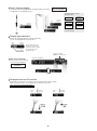
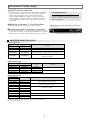
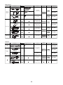
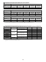
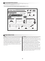
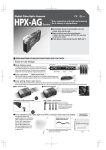
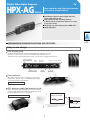
Digital Fiber-Optic Sensors
HPX-AG
Series
Easy operation and high performance
for a variety of applications
Dual display shows incoming light level and
preset value side by side.
High sensitivity and ultra long distance
(1,200mm with the standard HPF-T003 thru scan fiber
in high power mode)
Three types of auto-tuning: 2-point, BGS and %
RoHS-compliant
CLICK
EXPLANATION OF MAJOR FUNCTIONS AND FEATURES
Easy-to-use design
Dual display panel
The digital dual display panel indicates incoming light level and preset value side
by side, so it is easy to check current scanning status while setting the sensor.
The button layout is especially designed to ensure easy operation of gang-mounted sensors.
Auto-tuning button
Preset
value
Function selection button
Incoming
light level
Output indicator
+ Button
- Button
Easy operation
With controls that are as easy to operate as a conventional
potentiometer, and with easy-to-read digital display, settings
can be changed directly in RUN mode.
Digital manual tuning
APC ensures stable light emission level
Auto Power Control (APC, light emission level control) monitors
the level of light emitted by the LED, and regulates the current
to maintain light emission at a constant level.
Note: APC controls the light emission level of the LED emitter,
but does not compensate for a drop in received
light level due to other factors.
1
Light emission level
Stability when power is first
supplied is also improved.
Long and short term stabilization
Without APC circuit
Time
Advanced scanning performance for expanded possibilities
High sensitivity and ultra long distance
Five selectable sensing modes
High-level performance is achieved with the built-in APC.
Five sensing modes are selectable by desired response speed
and sensitivity, according to what is best for your application.
Sensing mode: HP
Response speed: 5ms
High sensitivity
1,200mm
With HPF-T003 standard
thru scan fiber unit.
Scanning distance
Sensing mode
Response speed
HP(high power)
5ms
nL(normal)
1ms
SF(semi-fast)
500µs
FT(fast)
250µs
HS(high speed)
High speed
Maximum
50µs
Long distance and high sensitivity modes:
Setting in 1-digit increments is possible.
High accuracy detection
Note: Under optimum conditions
With 1mm core dia.
HPF-T003 standard fiber unit
With 1mm core dia.
HPF-T003 standard fiber unit
With HPF-D034 coaxial
fiber unit
Countermeasures for short-distance saturation
New countermeasures have been added since the sales release
of the HPX Series. Even for small difference detection at short
distances or for a high reflection ratio on both target object and
background, HPX sensors deliver reliable detection performance.
With a target object
Without a target object
Target object
Background
SATURATION
Saturated
Short distance
anti-saturation mode
2
Cannot be set
Settable
Easy to operate
Easy auto-tuning
Percent (%) tuning
Patent Pending
For re-tuning on the same application, simply press the AUTO button in the % tuning setting mode.
Fewer detection errors due
to setting variations
Fewer tuning man-hours
With a target object
Without a target object
Incoming
light level
Incoming
light level
Example: % tuning at 95%
For the same environment or target object,
the ratio of two tuning levels with and without
a target object is approximately the same.
The setting range for % tuning
without a target object is 10 to 999%.
Easy re-tuning
Different time,
different person
—same setting!
Detection of remaining chips.....
Detection of liquid level.....
Setting can be based on
the background
with no chips present.
Tuning can be done only with no liquid present.
Incoming
light level
HPF-T034 pipe-mounted fiber-optic liquid-level sensor
Preset
value
Incoming
light level
Incoming
light level
% setting at 75%.
Tuning without a target object.
Preset value is set to 1500.
Incoming
light level
Incoming
light level
Operated without liquid
Lates, if the
background
darkens.....
Initial %
setting at 50%.
If inside wall
of pipe becomes stained.
Preset
value
Re-tuning at 75% without
a target object.
Preset value is now 1125.
Incoming
light level
Re-tuning at 50%
An LO signal is used for chip supply.
When used with incoming light level without liquid.
Remote tuning
BGS or % tuning can be done remotely from a connected device. Even when the light level
is dropping due to a change in tooling, application environment, or installation conditions,
stable and highly accurate detection can be assured by periodic re-tuning.
Flexibility for tooling changes
Long-term reliability
ON
PUSH
!
For remote full auto-tuning, use the HPX-AG03 series.
Remote tuning
Environment has worsened
due to paper powder.
3
Superior timer functions
The advanced functions of the HPX-AG's combination timer
go beyond the standard on-delay/off-delay functions
and the newer one-shot timer function.
Time chart—LO (light ON)
Timer setting time
Timer setting range
250µs / 500µs
1ms to 5ms
6ms to 99ms
100ms to 900ms
1s to 20s
Light
On-delay
ON
Off-delay
500µs
1ms
100ms
1s
Dark
OFF
One-shot
On-delay/o
ff-
Setting unit
delay
On-delay/o
ne
-shot
Heartbeat
Patent Pending
ON-delay and one-shot output are repeated at
regular intervals while an object is detected.
Detection status
Output status
Example application: In chip sorting,
an air jet is repeated at regular intervals
until a rejected chip is removed.
Output latch
When an object is detected (or is not detected),
latched output is turned ON, and remains ON no matter
what the detection status is.
Used for interlock
During
operation, the amplifier display blinks.
Detection status
Example application: An interlock
for liquid leakage detection, used
in combination with the HPF-D040
liquid leak fiber-optic detector.
Output status
OFF by latch cancellation
4
Peak / bottom display
Since peak and incoming light levels are displayed at the same time,
the light axis can be aligned precisely.
For more precise
light axis alignment
Selectable peak / bottom
display modes
Incoming
light level
Peak
Peak
Incoming
light level
Peak hold
&
Incoming
light level
Bottom hold
&
Incoming
light level
Peak hold
&
Bottom hold
Hold time can be selected from 2s,
10s, and unlimited.
Display type selection
Relative incoming light intensity (instead of absolute)
can also be displayed with the preset value.
Preset
value
Relative
intensity
Incoming light
level is 2000
The incoming light level is
indicated as a percentage
of the preset value (= 100%).
Scanning status can be
managed by ratio.
Key lock is toggled
ON/OFF as shown below.
Key lock cancellation
Key lock function
Key lock can be set for all keys,
or for all except tuning keys.
Accidental key-press
prevention
Displayed value shift function
This function compensates for variation in the incoming light level. The incoming
light level during operation can be adjusted to an easy-to-control value.
For control of incoming light level
Preset
value
Incoming
light level
Preset
value
Incoming
light level
Shift by
Shift by
-50
-220
5
REFERENCE DATE FOR TARGET DETECTION
Standard diffuse scan fiber
Standard thru scan fiber unit
Glass substrate
HPF-D002
Glass substrate
HPF-T003
Sensing mode: HP
Incoming
light level
(Be sure to test using an actual target object.)
Sensing mode: HP
Incoming light level characteristics
of glass substrate and wafer
100000
Basic glass
Vapor deposition glass
Black mask
10000
Edge detection repeatability accuracy
1000
100
0
5
10 15 20 25 30 35 40 45 mm
Black mask
Fiber unit with diffuse scan array
HPF-D026
Coaxial diffuse scan fiber unit
Lead frame
HPF-D034 / HPF-LU07
Sensing mode: HP
Incoming
light level
Small chip
Sensing mode: SF
Incoming light level characteristics
when used with a small chip
Incoming
light level
Incoming light level
characteristics
5000
10000
4500
1005 (front)
Green luster
4000
1005 (back)
White
3500
3000
2500
1000
2000
1005 chip (front)
1500
1000
500
0
100
30
80
130
2
3
4
5
6
7mm
180 mm
Be sure to use at focas point of the lens.
Incoming light level changes depending
on the size of the mark or spot.
1005 chip (back)
Lead frame size
35mm x 150mm
Pipe-mounted fiber-optic liquid-level
HPF-T032 / HPF-T034
Coaxial diffuse scan fiber unit
Liquid-level in pipe
Reject mark
HPF-D038 / HPF-LU08
Sensing mode: nL
For 8mm dia. pipe only: nL_L
Incoming
light level
Sensing mode: FT
Incoming light level characteristics
of gold pattern and reject mark on
gold pattern
4500
4000
3000
Catalog Pipe Presence Absence
listing diameter of liquid of liquid
TO32
TO34
Gold pattern
Reject mark
3500
Signal-to-noise ratio(SN) data
by pipe diameter Liquid: water
Gold pattern
Approx. 1mm dia.
SN
2500
2000
1500
6mm
9650
530
18
1000
8mm
5080
150
34
500
0
12mm
110
7560
69
19mm
75
5800
77
20
Values for presence or absence of liquid
are incoming light level values.
Reject mark
These high ratios of liquid-present to liquid-absent
light levels show that detection is fully reliable.
The reject mark is applied to
the gold pattern using an
oil-based red felt pen.
6
25
30
35
mm
40
Be sure to use at the lens focal point.
Incoming light level changes
depending on the size of mark and spot.
Environment-friendly design
RoHS Directive compliance
Yamatake products are developed to meet RoHS directives restricting
the use of hazardous substances such as lead, mercury, cadmium,
hexavalent chromium heavy metals, and the brominated flame
retardants PBB and PBDE. For example, non-halogen type flame
retardants that do not generate dioxin are used, and the polyethylene
used for packing material does not generate hazardous gas even
if it is burned.
The RoHS Directive
RoHS is European environmental directive. The
name is an abbreviation for Restriction of the Use
of Certain Hazardous Substances in Electrical and
Electronic Equipment.
Selection of standard 1, 2 and 5m cables
When monitor sleep mode is enabled, sleep mode begins whenever there is no
normal mode operation for 20 seconds. When any button is depressed, normal
operation mode resumes.
Optimum cable length can be selected for reduced waste.
Monitor sleep mode for low power consumption
The digital display can be set so that all display is off.In monitor sleep
mode, power consumption can be reduced to 500mW. Since 1-segment
display remains on, the power supply condition can still be checked.
One segment display changes in a fixed cycle.
AMPLIFIER SELECTION GUIDE
Cable lead-out type
Catalog listing
NPN
PNP
HPX-AG00-1
HPX-AG00-2
HPX-AG01-1
HPX-AG01-2
Features
Standard
Remote tuning input
HPX-AG02-1
HPX-AG02-2
Remote tuning input
Alarm (light level drop and stability safety margin) output
HPX-AG03-1
HPX-AG03-2
Remote tuning input
Tuning error output
Reduced wiring type
Catalog listing
NPN
PNP
HPX-AG00-3
HPX-AG00-4
HPX-AG00-5
HPX-AG00-6
HPX-AG01-3
HPX-AG01-4
HPX-AG01-5
HPX-AG01-6
Type
Features
Main unit
Expansion unit
Main unit
Expansion unit
Standard
Remote tuning input
Reduced wiring type
Catalog listing
NPN
HPX-AG04-3
HPX-AG04-5
HPX-AG06-3
HPX-AG06-5
HPX-AG07-3
HPX-AG07-5
HPX-AG08-3
HPX-AG08-5
HPX-AG09-3
HPX-AG11-3
HPX-AG11-5
Type
Features
Main unit
Expansion unit
Main unit
Expansion unit
Main unit
Expansion unit
Main unit
Expansion unit
Main unit
Main unit
Expansion unit
Advanced function timer (latch and heartbeat) function,
latch cancellation input, alarm output
Dual output, dual set values
Active zone setting
Differential setting, alarm output
Data bank setting, changeover input
Synchronous external input
Standard cable length is 2m. Catalog listings for 1m or 5m cable models have the
suffix -L01 or -L05 respectively.
7
AMPLIFIER SPECIFICATIONS
Catalog listing
Addition
NPN
HPX-AG00-1
HPX-AG00-3
HPX-AG00-5
HPX-AG01-1
HPX-AG01-3
HPX-AG01-5
PNP
HPX-AG00-2
HPX-AG00-4
HPX-AG00-6
HPX-AG01-2
HPX-AG01-4
HPX-AG01-6
−
−
−
Remote tuning
Output
Input
HPX-AG06-3
HPX-AG06-5
HPX-AG07-3
HPX-AG07-5
HPX-AG08-3
HPX-AG08-5
HPX-AG09-3
HPX-AG11-3
HPX-AG11-5
HPX-AG02-2
HPX-AG03-2
−
−
02- ,04- :alarm output
03- :error output
02- :remote tuning
03- :remote tuning
04- :latch cancellation
06-
:control output
−
08-
:alarm output
09-3:changeover 2-input
11- :synchronous input
12 to 24Vdc ±10% (ripple 10% max.)
Supply voltage
Current consumption
750mW max. (at 24V power supply and 30mA current consumption), monitor sleep mode 500mW max.
Hysteresis
20% max. (at rated scanning distance)
Operation mode
Control output
Light-ON / Dark-ON changeable (setting by changeover switch)
HPX-AG
-1/-3/-5: NPN transistor open collector. -2/-4/-6: PNP transistor open collector.
Cable lead-out type (1 output): switching current 100mA max. (resistive load), output voltage 26.4V, voltage drop 2V max. (switching current 100mA).
Cable lead-out type (2 output): switching current 50mA max. (resistive load), output voltage 26.4V, voltage drop 2V max. (switching current 50mA).
Reduced wiring type (1 output): switching current 50mA max. (resistive load), output voltage 26.4V, voltage drop 2V max. (switching current 30mA).
Reduced wiring type (2 output): switching current 30mA max. (resistive load), output voltage 26.4V, voltage drop 2V max. (switching current 30mA).
External input
When ON (short-circuit current is approx. 1mA): DC 0—1V. When OFF: open or connection to + side of power supply
Response time
Timer function
HPX-AG02-1
HPX-AG03-1
HPX-AG04-3
HPX-AG04-5
50µs (High Speed), 250µs (Fast), 500µs (Semi-Fast), 1ms (Normal) and 5ms (High Power)
Type
Timer OFF, ON delay, OFF delay, one shot, ON-delay + one shot , and ON delay + OFF delay.
04_ : ON heartbeat , OFF heartbeat, ON delay + heartbeat, and OFF delay + heartbeat.
Positive edge latch, negative edge latch, ON delay + positive edge latch, and ON delay + negative edge latch.
Preset
value
200µs, 500µs and 1ms to 4.5ms: 1ms unit, 500µs unit and 5 to 99ms: 1ms unit, 100ms to 900ms: 100ms unit, and 1s to 20s: 1s unit.
Heartbeat only: 1ms to 4.5ms: 1ms unit, 500µs unit and 5 to 99ms: 1ms unit, 100ms to 900ms: 100ms unit, and 1s to 20s: 1s unit.
Light emitter
Display function
Red LED
Output indicator: orange. Preset value: green 4-digit LED. Incoming light level: red 4-digit LED.
Preset value + incoming light level / preset value + relative value / peak + incoming / bottom + incoming / peak + bottom.
Reduced wiring type addition
Up to 15 expansion units can be connected.
Ambient light immunity
Incandescent light: 5,000 lux max. Sunlight: 20,000 lux max.
Operating temperature
-20 to +55˚C*
Storage temperature
-40 to +70˚C
Operating humidity
35 to 85% (no condensation allowed)
Vibration resistance
10 to 55Hz, 1.5mm peak-to-peak amplitude, 2 hours each in X, Y and Z directions
500mm2, 3 times each in X, Y and Z directions
Shock resistance
Weight
Circuit protection
HPX-AG
-1/-2/-3/-4: approx. 75g, -5/-6: approx. 40g (body only with 2m cable)
Power supply reverse connection protection circuit, malfunction prevention circuit at power ON (approx. 200ms), output short-circuit protection circuit
*Operating temperature is different depending on the number of gang-mounted sensor units.
1 or 2 units: -20 to +55˚C, 3 units: -20 to +50˚C, 4 or 5 units: -20 to +45˚C, 6 units: -20 to +40˚C
8
FIBER UNIT AND SENSING TYPE COMBINATIONS
Thru scan
Group
Appearance
Sensing type
3
Long
distance
11
Scanning distance (mm)
M4
nL
SF
635
FT
215
HS
3
2,230
1,450
1,160
HP
Core: 1.4 dia. (1)
Features
Cable length
(cuttable)
Bend radius
HPF-T001
Long scanning
distance
Cut to length
2m
R20
HPF-T002
15
Core: 1.4 dia. (1)
Catalog listing
3 dia.
Lens
3
HPF-T003
11
Core: 1 dia. (1)
M4
Sleeve 1.2 dia.
Lens
3
R20
Standard
HPF-T004
15
Core: 1 dia. (1)
3 dia.
Sleeve 1.2 dia.
HP
nL
Standard
10
SF
10
65 ± 4
15
FT
M4
Core: 1 dia. (1)
10
HS
120
350
800
640
1,200
HPF-T005
Cut to length
2m
Sleeve
(flexible)
R10/R20
HPF-T006
10
65 ± 4
15
3 dia.
Core: 1 dia. (1)
9.5
13.5
Core: 1 dia. (1)
M3
HP
nL
SF
11
FT
Core: 0.5 dia. (1)
M3
HS
140
95
75
42
14
Standard diameter
and
compact
R20
HPF-T045
Static installation,
flexible, and
small diameter
R1
HPF-T024
Lens
3 ± 0.3
Ultra
bend tolerant
11
HP
Core: 1 dia. (1)
M4
nL
SF
FT
HS
90
260
600
470
HPF-T025
865
Static installation,
flexible, and
standard model
Cut to length
2m
R2
HPF-T031
8
Core: 1 dia. (1)
3 dia.
15 ± 3
12
HP
nL
SF
FT
Sleeve 1 dia.
3
11
2.5 dia.
HS
Lens
HP
5
55
35
28
15
5
5
nL
SF
15
Core: 1 dia. (1)
10
Front view
15
10
Side view
Cut to length
2m
R15
HPF-T007
Fine diameter
sleeve
Cut to length
1m
R5
HPF-T037
Standard diameter
Cut to length
2m
R20
HPF-T042
Fine diameter
Cut to length
2m
R15
HPF-T015
2-M3
nL
SF
FT
15
15
HS
HP
nL
SF
FT
Sleeve 0.88 dia.
2.5 dia.
35
HS
55
35
28
15
5
HP
nL
SF
FT
3 dia.
Sleeve 1 dia.
HS
65
HP
34
25
20
11
4
nL
Small
diameter
5±2
Core: 0.25 dia. (1)
SF
15
FT
3 dia.
HPF-T028LF
Small diameter
sleeve
HP
Side view
R5
145
110
90
48
17
12
2.5 dia.
HPF-T028
Static installation,
flexible, standard, and
flat side view model
FT
HS
Sleeve 1 dia.
R1
210
140
110
60
21
HP
nL
10
15 ± 3
HPF-T010
Static installation,
flexible,
small diameter,
and flat top view model
SF
Core: 1 dia. (1)
R20
140
95
75
42
14
FT
3.3
Elbow
865
HP
HS
5
1.75 light axis center
HPF-T026
85
SF
Core: 0.5 dia. (1)
250
R1
HS
nL
10
Space
saving
FT
M4
570
450
Static installation,
flexible, and
side view model
HS
440
350
190
Cut to length
2m
660
9
Group
Appearance
HP
nL
6
SF
10
FT
Core: 0.125 dia. (1)
1.5 dia.
HS
HP
nL
SF
6
FT
Core: 0.25 dia. (1)
1.0 dia.
Sleeve 0.4 dia.
HS
HP
nL
5
Small
diameter
Scanning distance (mm)
Sensing type
SF
10
FT
Core: 0.125 dia. (1)
HS
Sleeve 0.4 dia.
HP
nL
SF
60 ± 3
15
Core: 0.25 dia. (1)
FT
3 dia.
HS
HP
nL
SF
22
FT
Core: 0.5 dia. (1)
2 dia.
HS
17
12
10
5
2
Connector
0.5m
17
12
10
5
2
Fine diameter
sleeve
35
20
18
10
5
Fine diameter
sleeve
300
200
160
90
28
Small diameter
nL
FT
M3
HS
HP
nL
SF
11
FT
Core: 0.25 dia. (1)
M3
HS
HP
nL
Elastic
SF
15
FT
Core: 0.25 dia. (4)
1..5 dia.
HS
Lens
HP
65
450
360
195
M4
HS
Lens
HP
Core: 0.25 dia. (16)
95
nL
3
SF
11
FT
Core: 1 dia. (1)
M4
HS
70
280
650
520
Heat
resistant
M4
Lens
HP
Core: 1.5 dia. (1)
120
nL
3
15
(10)
Glass fiber:
1 dia. (0.05 dia. x 320) (1)
SF
FT
M4
HS
Lens
HP
60
410
325
180
nL
3
SF
17
FT
30
Glass fiber:
0.05 dia. (0.05 dia. x 370)
M4
(Lens incorporated)
HS
65
440
355
190
FT
M4
410
HP
Narrow
beam
1.3
nL
4.3
(Lens incorporated)
SF
FT
4 dia.
(Lens incorporated)
450
HS
HP
nL
17
SF
11
FT
M4
360
HS
Mapping
9
nL
7.5
10
15
7.5
8
15
nL
FT
HS
80
230
HPF-T017
520
415
R15
HPF-T018
Heat and
cold resistant from
-60˚C to +350˚C
Connector
2m
R25
HPF-T014
4,540
3,000
2,390
1,300
Parallel beam
side view
3,600
2,400
1,920
1,050
Narrow beam
top view
80
SF
R35
Connector
1m
Parallel beam
top view
FT
HP
Wide beam
HPF-T012
To 200˚C
4,110
2,760
2,200
1,200
SF
HS
15
To 150˚C
500
500
HP
(Lens
incorporated)
Core:
1.5 dia. (1)
R25
Cut to length
2m
1200
660
HP
HS
HPF-T033
620
SF
11
Elastic standard
diameter
To 105˚C
nL
17
HPF-T009
940
800
640
350
R4
700
460
365
200
FT
HPF-T043
HPF-T044
Cut to length
2m
SF
HS
Cut to length
2m
HPF-T008
nL
15
17
HPF-T040
Elastic small
diameter
HP
1
HPF-T039
Small diameter and
long scanning distance
180
120
100
50
18
FT
HPF-T038
675
180
120
100
50
18
SF
11
Catalog listing
R15
nL
3
Bend radius
Fine diameter
34
25
20
11
4
SF
Core: 0.75 dia. (1)
Cable length
(cuttable)
HPF-T036
HP
11
Features
HPF-T019
R20
Cut to length
2m
HPF-T020
R15
HPF-T023
Narrow beam
-1.5˚/+1.5˚max.
side view
Cut to length
2m
R5
HPF-T030
Array
Cut to length
2m
R4
HPF-T021
790
10
Diffuse scan
Group
Appearance
Scanning distance (mm)
Sensing type
HP
Long
distance
nL
3
SF
20
175
FT
Core: 1.4 dia. (2)
M6
HS
48
285
400
Features
Cable length
(cuttable)
Bend radius
Catalog listing
Long scanning
distance
Cut to length
2m
R20
HPF-D001
580
HPF-D002
3
20
2.5 dia.
Standard
HP
Core: 1 dia. (2)
M6
Core: 1 dia. (2)
SF
FT
20
65 ± 4
nL
HS
36
HP
25
19
15
8
2
215
nL
SF
FT
Core: 0.5 dia. (2)
M3
HS
HP
nL
SF
3
20
FT
Core: 1 dia. (2)
M6
Sleeve 1.2 dia.
40 ± 2
11
10
Standard
Cut to length
2m
R20
HPF-D003
HPF-D032
Standard diameter
R5
HPF-D044
R2
HPF-D045LF
FT
HS
HP
nL
SF
FT
3 dia.
Core: 1 dia. (2)
15
10
3.3
HS
HP
nL
5
1.5 light axis center
10
SF
2-M3
Core:
1 dia. (2)
HPF-D031
R1/R4
HP
30
R10/R1
Coaxial
Lens
nL
15
HPF-D030
50
35
25
14
4
HS
M3
R2
Small diameter
sleeve (bendable)
SF
Core: 0.5 dia. (emitter core dia.)(1)
Core: 0.25 dia. (receiver core dia.)(4)
Standard
25
19
15
8
2
M4
18
HPF-D029
HP
SF
Core: 0.5 dia. (2)
R1
18
nL
10
230
160
115
70
Small diameter
HS
FT
Compact
430
M6
11
Ultra
bend tolerant
130
300
FT
HS
70
24
160
130
Cut to length
2m
240
105
70
55
30
10
Static installation,
flexible, standard, and
flat side-view model
Cut to length
2m
HPF-D004
11
Core: 0.5 dia. (2)
M3
HP
nL
SF
15
FT
Core: 0.5 dia. (2)
3 dia.
Sleeve 1.2 dia.
65 ± 4
11
HS
Small diameter
110
80
60
35
10
HPF-D005
Cut to length
2m
Lens
Small diameter
sleeve
10
10
Core: 0.5 dia. (2)
HP
Small
diameter
nL
SF
15
FT
Core: 0.75 dia. (2)
M4
Sleeve 0.82 dia.
HS
HP
nL
15 ± 2
SF
15
Core: 0.25 dia. (2)
FT
3 dia.
Sleeve 1.5 dia.
HS
HP
nL
15 ± 2
SF
10
Core: 0.5 dia. (2)
FT
3 dia.
Sleeve 0.82 dia.
HS
HP
nL
5±2
SF
10
FT
Core: 0.25 dia. (2)
HS
150
110
65
18
R15
215
Small diameter
long scanning
distance
11
8
6
4
1
95
65
45
28
8
11
8
6
4
1
HP
3
Coaxial
HPF-D006
M4
nL
20
SF
Core: 1 dia. (emitter core dia.)(1)
Core: 0.25 dia. (receiver core dia.)(16)
FT
M6
HS
Lens
HP
nL
18
Core: 0.5 dia. (emitter core dia.)(1)
Core: 0.25 dia. (receiver core dia.)(4)
SF
FT
M3
HS
36
130
215
300
HPF-D018
Fine diameter
sleeve
Cut to length
0.5m
HPF-D019
Small diameter
sleeve
Cut to length
2m
HPF-D021
Fine diameter
sleeve
Cut to length
0.5m
R4
HPF-D039
R20
HPF-D009
R15
HPF-D010
430
Coaxial
Cut to length
2m
95
65
45
28
8
Coaxial
11
Group
Appearance
18
Scanning distance (mm)
Sensing type
Lens
HP
nL
23
SF
Core: 0.25 dia. (emitter core dia.)(1)
Core: 0.25 dia. (receiver core dia.)(6)
FT
M3
HS
Features
70
45
30
20
5
Cable length
(cuttable)
Bend radius
Catalog listing
Connector
0.5m
R4
HPF-D034
Lens
18
Coaxial
5
Core: 0.5 dia. (emitter core dia.)(1)
Core: 0.25 dia. (receiver core dia.)(9)
HP
M3
Lens
nL
SF
FT
HS
16
Core: 0.5 dia. (emitter core dia.)(1)
Core: 0.25 dia. (receiver core dia.)(9)
22
HP
nL
Sleeve 2 dia.
Core: 0.5 dia. (emitter core dia.)(1)
Core: 0.25 dia. (receiver core dia.)(9) 3 dia.
40 ± 4
Cut to length
2m
SF
FT
HS
100
65
50
30
10
15
HP
3 dia.
Core: 0.5 dia. (2)
15
R15
HPF-D038
M4
15
Sleeve 2 dia.
HPF-D035
Coaxial
95
95
70
40
11
nL
SF
15
FT
HS
Side view
45
30
20
13
4
Small diameter
coaxial
HPF-D042
Small diameter
sleeve
HPF-D011
R15
Small diameter
short sleeve
Cut to length
2m
HPF-D041
2.8 dia.
35
HP
nL
SF
FT
6 dia.
HS
180
120
95
50
18
HP
3
Cut to length
2m
17
15
11
7
2
Small diameter
sleeve
Connector
1m
21
15
11
7
2
Small diameter
Cut to length
2m
FT
M6
6
HS
24
HP
nL
10
SF
Core: 0.25 dia. (emitter core dia.)(2)
Core: 0.25 dia. (receiver core dia.)(2) 1.5 dia.
FT
HS
HP
nL
10
SF
Core: 0.25 dia. (emitter core dia.)(2)
Core: 0.25 dia. (receiver core dia.)(2)
FT
M3
HS
80
190
190
140
HP
nL
3
SF
20
FT
Core: 1 dia. (2)
M6
HS
24
80
To 105˚C
HP
nL
3
SF
13
17
Heat
resistant
2
14
M6
10
HS
HP
M6
Glass fiber: 1.4 dia.
Sleeve 2.1 dia.
nL
SF
FT
HS
5
70
3
215
SF
FT
Glass fiber: 1.5 dia.
M6
(Built-in lens)
HS
18
HP
20
20
20
20
20
nL
SF
20.5
FT
M5
HS
70
20
15
10
10
13
20
nL
SF
FT
HS
HP
nL
12
(4.5)
Limited
reflection
SF
3
19
7
4
FT
24
90
200
150
R4
HPF-D036
HPF-D037
R25
HPF-D013
R35
HPF-D022
HPF-D023
To 200˚C
Connector
1m
R15
Sleeve
heat resistant to
200˚C
160
160
120
HP
Wide
beam
To 150˚C
190
130
95
60
16
HP
nL
HPF-D012
Cut to length
2m
430
M6
17
25
(10.7)
36
300
19
Glass fiber: 1.4 dia.
Parallel
beam
130
FT
Core: 1.5 dia. (2)
HPF-D043
265
Standard
SF
Core: 0.25 dia. (emitter core dia.)(16)
Core: 0.25 dia. (receiver core dia.)(16)
Elastic
190
140
nL
20
R20
Standard diameter
HPF-D024
Heat and
cold resistant from
-60˚C to 350˚C
Cut to length
2m
R25
HPF-D015
Parallel beam
reflection
Cut to length
2m
R15
HPF-D025
Array
Cut to length
2m
R4
HPF-D026
Limited reflection
Cut to length
2m
R15
HPF-D028
290
2.5 ± 0.5
2.5 ± 0.5
HS
12
Wet process
Group
Appearance
Sensing type
(Built-in lens)
Scanning distance (mm)
nL
SF
5
13.7
FT
Core:
3 dia. (effective lens dia.)(1)
4.7 dia.
360
HS
HP
14.8
Oil and
chemicalproof
nL
5
SF
FT
4.7 dia.
HS
HP
nL
SF
16
FT
Core: 1 dia. (2)
6 dia.
HS
85
300
490
Features
Cable length
(cuttable)
Bend radius
4,500
3,000
2,160
1,300
HP
690
HPF-T029
PFA tube
small diameter
1,030
R20
Cut to length
2m
190
130
95
60
16
Pipe-mounted.
Light received when
liquid present.
3 to 13mm dia. pipes.
Pipe-mounted.
Light received when
liquid absent.
8 to 19mm dia. pipes.
28
Liquid level
6 dia.
HPF-D014
HPF-T032
Cut to length
5m
R4
HPF-T034
Contact type.
PFA tube 6mm dia.
20
(60)(Bending not allowed)
HPF-T035
R25/R80
PFA tube
28
Catalog listing
R25/R40
HPF-D027
R15/R30
HPF-D033
Cut to length
2m
Contact type.
PFA tube 4mm dia.
15
(40)(Bending not allowed)
4 dia.
4
13
30.9
20
Liquid leak
Contact type
Cut to length
5m
R20
HPF-D040
Features
Cable length
(cuttable)
Bend radius
Catalog listing
24
Vacuum
Group
Appearance
Sensing type
Lens
Thru
scan
3
Glass fiber:
1.2 bundle dia. (1)
3
Diffuse
scan
HP
nL
SF
20
FT
30
M4
20
35
HS
HP
Glass fiber: 1.7 bundle dia.
M6
nL
SF
FT
Glass fiber: 1.7 bundle dia.
10
360
240
170
105
30
HPF-VT07
Heat resistant to
350˚C.
Elbow connection
35
35
35
15
Connector
1m
R25
Heat resistant to
350˚C.
Straight connection
HS
3 20
35
2
Scanning distance (mm)
M6
Air side
10
HPF-VD07
HPF-VD09
Cut to length
2m
R20
HPF-VA01
Core: 1 dia.
8
6.8
7
2.5
(8)
22
Heat resistant to
200˚C.
Light connector
13
HPF-VJ03
SCANNING DISTANCE WHEN USED WITH ATTACHMENT
FE-PA-L1 long-distance lens unit
Attachment
Sensing
mode
Fiber unit
High Power/ 5ms
Nor mal/1ms
HPF -T003/T004
HPF -T010
HPF -T012
HPF-T014
HPF-T018
8,400mm
4,800mm
6,000mm
3,400mm
3,000mm
1,850mm
4,500mm
2,600mm
4,300mm
2,480mm
FE-PA-S1 or HPF-VL05 side view lens unit
Attachment
Sensing
mode
Fiber unit
High Power/5ms
Normal/1ms
HPF -T003/T004
HPF -T012
HPF -T014
HPF -T018
HPF - VT07
1,400mm
800mm
670mm
370mm
570mm
330mm
550mm
310mm
420mm
240mm
HPF-VL06 ultra long distance lens unit
Attachment
Sensing
mode
Fiber unit
High Power/5ms
Nor mal/1ms
HPF -T003/T004
HPF -T012
HPF -T014
HPF -T018
HPF - VT07
14m
8m
5m
3.1m
7.7m
4.4m
7.2m
4.2m
4.2m
2.4m
Notes : 1. Values indicate capability. Actual scanning distance is limited by fiber length (standard 2m x 2 4m).
2. The data for combinations with the HPF-VT07 assumes that it is used with the HPF-VJ03 light connector and the HPF-VA01 fiber unit for air.
CHARACTERISTICS OF COAXIAL DIFFUSE SCAN FIBER UNIT AND LENS ATTACHMENT (spot diameter) COMBINATIONS
Fiber unit catalog listing
HPF -D034
HPF -D010
HPF -D032
HPF -D035
HPF -D034
HPF -D010
HPF -D032
HPF -D035
HPF -D010
HPF -D032
HPF -D035
HPF -D034
HPF -D038
HPF -D025
Lens catalog listing
Scanning distance / spot diameter
High Power
Normal
High Speed
4.6mm / approx. 0.1mm
HPF-LU07
4.6mm → approx. 0.2mm
7mm → approx. 0.2mm
HPF-LU01
HPF-LU02
HPF-LU08
—
*
7mm → approx. 0.4mm
19mm → approx. 0.2mm
19mm → approx. 1mm
33mm → approx. 1mm
Depends on amplifier used.
Notes : 1. The HPF-D025 is not combined with a lens.
2. This data is based on a standard target (white paper). For individual applications, check detection under actual operating circumstances.
3. : Applicable. : Detection may be possible, depending on the target.
*
14
*
*
*
*
*
WIRING DIAGRAM FOR AMPLIFIER
Input/output circuit and connection NPN type
Input/output circuit and connection PNP type
Brown *1
Output 2
Black
Black Output 1
Load
Orange *2
Main circuit
Main circuit
Output 1
Brown *1
Load
12 to 24Vdc
Blue *1
External input 1 *3
Pink
External input 2 *4
White
Load
Blue *1
External input 1 *3
*1. Power to expansion units is supplied through the main unit.
*2. HPX-AG02/03/04/06/08- only.
*3. HPX-AG01/02/03/09/11- only.
*4. HPX-AG09-3 only.
12 to 24Vdc
Output 2 Orange 2
*
Load
Pink
*1. Power to expansion units is supplied through the main unit.
*2. HPX-AG02/03- only.
*3. HPX-AG01/02/03- only.
EXTERNAL DIMENSIONS
(unit: mm)
*4
*5
95.5
10
5˚
0˚
14
10
6.2
*1. Mounting bracket sold separately (catalog listing: HPX-PA04).
*3
2. Materials.
Case: PC resin, black
Control panel cover: PC resin, gray transparent
Mounting bracket: Stainless steel plate
*3. Oil-resistant cable.
(4.2)
(3.3 dia. hole)
2-core: AG06-5, AG08-5, AG11-5
3-core: AG00-1/2/3/4, AG04-5, AG07-3
4-core: AG01-1/2/3/4, AG06-3, AG083, AG11-3
5-core: AG02-1/2, AG03-1/2, AG04-3, AG09-3
For the above units: outer diameter 4.2, insulator diameter 1.2,
and nominal cross-section 0.2mm2. Sheath color is gray.
3.7
3.4
5.5
11.2
30.2
15.9
(35.2)
1
1
70.2
1-core: AG00-5/6, AG07-5
Outer diameter 2.6, insulator diameter 1.2, nominal cross-section 0.2mm2.
Sheath color is gray.
Mounting bracket*1
(3-3.3)
33.9
Notes:
(3-2.2)
*4. Female connector structure for attaching a reduced wiring connector
(for both main unit and expansion unit).
*5. Reduced-wiring type expansion unit has a connector structure (male)
for attaching additional units.
(25.2)
(16)
15
HPX-AG REFERENCE MANUAL
Frequently used operations are summarized on this card. For more detail, refer to the user's
manual included with the HPX-AG digital fiber-optic sensor.
Peel-off reference stickers are also available in Japanese, English or Chinese.
REFERENCE MANUAL
Hold key
down
Single
press
Key lock
Amplifier operator unit
Press, or hold for
auto increment/
decrement/cycle
* Locks the keys.
Function selection button
Auto-tuning button
Preset value Incoming light level
FUNC
Also an OK
button for
setup.
Output indicator +Button
Manual tuning
-Button
LO/DO selection
Sensing type selection
1 Press FUNC once.
1 Press FUNC for 3+ seconds.
+
-
Set value
increases.
Set value
decreases.
+
Hold FUNC and press + for 3+
seconds to set key lock or cancel it.
Also used
to cancel a
function.
2 Press AUTO once.
2 Use + and - to select LO/DO.
3 Use + and - to select.
3 Press AUTO/OK to set.
4 Press AUTO/OK to set.
Auto-tuning
2Pnt(2-point tuning): Press AUTO once with target object and once without it.
bgS
(BGS tuning)
2
: 1 Press AUTO once. 2 Hold AUTO for 3+ seconds.
2 Use + and - to set the %. 3 Press AUTO once.
Pcnt (percent tuning): 1 Press AUTO once. Note: For other operations, refer to the user's manual.
BASIC PRECAUTIONS
Wiring
•
Handling
If an extension is necessary, use cable at least 0.3mm2 in dia. and at most
100m long.
If the wires of photoelectric sensor are laid in the same
conduit as high-voltage or power lines, inductance may cause malfunction or
damage. Isolate the photoelectric sensor's cable or lay it in a separate
conduit.
When using a commercially available switching regulator, ground
the frame ground and ground terminals. If used without grounding, switching
noise may cause malfunction. When using a load which generates an
inrush current above the switching capacity, such as a capacitive load or
incandescent lamp, connect a current-limiting resistor between the load and
the output terminals. (Otherwise, the output short-circuit protection function
will be activated.)
•
•
•
•
Output is disabled upon power-up for approx. 200ms until the unit
stabilizes.
When used in an environment with much dust, be sure to take
countermeasures to keep dust away from the sensor head by using a sealed
case or air purge.
Use a cover or change the mounting direction to ensure
the sensor's correct operation if interference from ambient light is
considerable.
Even when oil-resistant cable is used, do not use in a
location subject to continuous splashing by water or oil, or where the unit is
dipped in liquid. Ensure that the end of the cable is not subject to splashing
by water or oil.
Water or oil splashed on the fiber head may cause
incorrect operation. Shield the sensor head to prevent direct splashes.
Do
not use where exposed to chemicals (organic solvents, acids, alkalis, etc.)
To clean the sensor head, wipe lightly with a soft, clean cloth. Do not use
an organic solvent such as benzine or paint thinner.
Pulling with
excessive force may break the cable. Do not apply a force of more than 50N.
Do not bend the part of the cable nearest to the amplifier beyond the bend
radius of 30mm. Avoid continuous bending stress.
The detection distance
or display value may vary depending on variations in the individual amplifier,
installation circumstances, and/or type of fiber unit.
•
•
•
•
•
•
16
•
•
•