1
Freescale Semiconductor, Inc.
MCUEZLNK0508/D
Freescale Semiconductor, Inc...
February 1998
MCUez
LINKER
USER'S MANUAL
© Copyright 1998 MOTOROLA and HIWARE AG; All Rights Reserved
For More Information On This Product,
Go to: www.freescale.com
Freescale Semiconductor, Inc.
Freescale Semiconductor, Inc...
Important Notice to Users
While every effort has been made to ensure the accuracy of all information in this document,
Motorola assumes no liability to any party for any loss or damage caused by errors or omissions
or by statements of any kind in this document, its updates, supplements, or special editions,
whether such errors are omissions or statements resulting from negligence, accident, or any other
cause. Motorola further assumes no liability arising out of the application or use of any
information, product, or system described herein; nor any liability for incidental or consequential
damages arising from the use of this document. Motorola disclaims all warranties regarding the
information contained herein, whether expressed, implied, or statutory, including implied
warranties of merchantability or fitness for a particular purpose. Motorola makes no
representation that the interconnection of products in the manner described herein will not
infringe on existing or future patent rights, nor do the descriptions contained herein imply the
granting or license to make, use or sell equipment constructed in accordance with this
description.
Information contained in this document applies to
REVision (0) MCUez.
The computer program contains material copyrighted by Motorola Inc., first published 1997, and may
be used only under a license such as the License For Computer Programs (Article 14) contained in
Motorola's Terms and Conditions of Sale, Rev. 1/79.
Trademarks
This document includes these trademarks:
MCUez is a trademark of Motorola Inc.
EXORciser is a trademark of Motorola Inc.
The MCUez development, emulation, and debugging application is based on HI-WAVE; a
software technology developed by HIWARE. HI-WAVE is a registered trademark of HIWARE
AG.
AIX, IBM, and PowerPC are trademarks of International Business Machines Corporation.
SPARC is a trademark of SPARC international, Inc.
Sun and SunOS are trademarks of Sun Microsystems, Inc.
UNIX is a trademark of Novell, Inc., in the United States and other countries, licensed
exclusively through X/Open Company, Ltd.
X Window System is a trademark of Massachusetts Institute of Technology.
For More Information On This Product,
Go to: www.freescale.com
Freescale Semiconductor, Inc.
CONTENTS
CONTENTS
CHAPTER 1 GENERAL INFORMATION
1.1 INTRODUCTION . . . . . . . . . . . . . . . . . . . . . . . . . . . . . . . . . . . . . . . . . . . . . . . . . . . . . . . . . . 1-1
1.2 FUNCTIONAL DESCRIPTION . . . . . . . . . . . . . . . . . . . . . . . . . . . . . . . . . . . . . . . . . . . . . . . 1-1
Freescale Semiconductor, Inc...
1.3 FEATURES . . . . . . . . . . . . . . . . . . . . . . . . . . . . . . . . . . . . . . . . . . . . . . . . . . . . . . . . . . . . . . . . 1-1
1.4 SUPPORT INFORMATION . . . . . . . . . . . . . . . . . . . . . . . . . . . . . . . . . . . . . . . . . . . . . . . . . . 1-2
CHAPTER 2 USER INTERFACE
2.1 INTRODUCTION . . . . . . . . . . . . . . . . . . . . . . . . . . . . . . . . . . . . . . . . . . . . . . . . . . . . . . . . . . 2-1
2.2 INTERACTIVE USER INTERFACE . . . . . . . . . . . . . . . . . . . . . . . . . . . . . . . . . . . . . . . . . . . 2-1
2.2.1 Starting the MCUez Linker . . . . . . . . . . . . . . . . . . . . . . . . . . . . . . . . . . . . . . . . . . . . . . . . 2-1
2.2.2 Starting from WinEdit or Codewright . . . . . . . . . . . . . . . . . . . . . . . . . . . . . . . . . . . . . . . . 2-2
2.2.3 Linker Graphical Interface . . . . . . . . . . . . . . . . . . . . . . . . . . . . . . . . . . . . . . . . . . . . . . . . 2-2
2.2.3.1 Window Title . . . . . . . . . . . . . . . . . . . . . . . . . . . . . . . . . . . . . . . . . . . . . . . . . . . . . . . 2-3
2.2.3.2 Content Area . . . . . . . . . . . . . . . . . . . . . . . . . . . . . . . . . . . . . . . . . . . . . . . . . . . . . . . 2-3
2.2.3.3 Tool Bar . . . . . . . . . . . . . . . . . . . . . . . . . . . . . . . . . . . . . . . . . . . . . . . . . . . . . . . . . . . 2-4
2.2.3.4 Status Bar . . . . . . . . . . . . . . . . . . . . . . . . . . . . . . . . . . . . . . . . . . . . . . . . . . . . . . . . . 2-5
2.2.3.5 Linker Menu Bar . . . . . . . . . . . . . . . . . . . . . . . . . . . . . . . . . . . . . . . . . . . . . . . . . . . . 2-6
2.2.3.6 File Menu . . . . . . . . . . . . . . . . . . . . . . . . . . . . . . . . . . . . . . . . . . . . . . . . . . . . . . . . . 2-6
2.2.3.6.1 Important remarks . . . . . . . . . . . . . . . . . . . . . . . . . . . . . . . . . . . . . . . . . . . . . . 2-11
2.2.3.6.2 Save Configuration Dialog . . . . . . . . . . . . . . . . . . . . . . . . . . . . . . . . . . . . . . . . 2-11
2.2.3.7 Linker Menu . . . . . . . . . . . . . . . . . . . . . . . . . . . . . . . . . . . . . . . . . . . . . . . . . . . . . . 2-12
2.2.3.8 View Menu . . . . . . . . . . . . . . . . . . . . . . . . . . . . . . . . . . . . . . . . . . . . . . . . . . . . . . . 2-13
2.2.3.9 Advanced Options Dialog Box . . . . . . . . . . . . . . . . . . . . . . . . . . . . . . . . . . . . . . . . 2-13
2.2.4 Message Settings Dialog Box . . . . . . . . . . . . . . . . . . . . . . . . . . . . . . . . . . . . . . . . . . . . . 2-14
2.2.4.1 Changing the Class Associated With a Message . . . . . . . . . . . . . . . . . . . . . . . . . . . 2-15
2.2.4.2 Specifying the Input File . . . . . . . . . . . . . . . . . . . . . . . . . . . . . . . . . . . . . . . . . . . . . 2-16
2.2.4.2.1 Using the Editable Combo Box in the Tool Bar. . . . . . . . . . . . . . . . . . . . . . . . 2-16
2.2.4.2.2 Using the Entry File | Link ... . . . . . . . . . . . . . . . . . . . . . . . . . . . . . . . . . . . . . . 2-16
2.2.4.2.3 Using Drag and Drop . . . . . . . . . . . . . . . . . . . . . . . . . . . . . . . . . . . . . . . . . . . . 2-16
2.2.5 Error Feedback . . . . . . . . . . . . . . . . . . . . . . . . . . . . . . . . . . . . . . . . . . . . . . . . . . . . . . . . 2-16
2.2.5.1 Error Feedback Using Information From the Linker Window . . . . . . . . . . . . . . . . 2-17
2.2.5.2 Error Feedback Using a User-Defined Editor . . . . . . . . . . . . . . . . . . . . . . . . . . . . . 2-17
2.2.5.2.1 Line Number Can be Specified on the Command Line . . . . . . . . . . . . . . . . . . 2-17
2.2.5.2.2 Line Number Cannot be Specified on the Command Line . . . . . . . . . . . . . . . 2-17
iii
MCUEZLNK0508/D
For More Information On This Product,
Go to: www.freescale.com
Freescale Semiconductor, Inc.
CONTENTS
CHAPTER 3 ENVIRONMENT VARIABLES
3.1 INTRODUCTION . . . . . . . . . . . . . . . . . . . . . . . . . . . . . . . . . . . . . . . . . . . . . . . . . . . . . . . . . . 3-1
Freescale Semiconductor, Inc...
3.2 SETTING PARAMETERS . . . . . . . . . . . . . . . . . . . . . . . . . . . . . . . . . . . . . . . . . . . . . . . . . . . 3-1
3.3 PATH VARIABLES . . . . . . . . . . . . . . . . . . . . . . . . . . . . . . . . . . . . . . . . . . . . . . . . . . . . . . . . .
3.3.1 LINKOPTIONS . . . . . . . . . . . . . . . . . . . . . . . . . . . . . . . . . . . . . . . . . . . . . . . . . . . . . . . .
3.3.2 GENPATH . . . . . . . . . . . . . . . . . . . . . . . . . . . . . . . . . . . . . . . . . . . . . . . . . . . . . . . . . . . . .
3.3.3 OBJPATH . . . . . . . . . . . . . . . . . . . . . . . . . . . . . . . . . . . . . . . . . . . . . . . . . . . . . . . . . . . . .
3.3.4 ABSPATH . . . . . . . . . . . . . . . . . . . . . . . . . . . . . . . . . . . . . . . . . . . . . . . . . . . . . . . . . . . . .
3.3.5 TEXTPATH . . . . . . . . . . . . . . . . . . . . . . . . . . . . . . . . . . . . . . . . . . . . . . . . . . . . . . . . . . . .
3.3.6 SRECORD . . . . . . . . . . . . . . . . . . . . . . . . . . . . . . . . . . . . . . . . . . . . . . . . . . . . . . . . . . . .
3.3.7 ERRORFILE . . . . . . . . . . . . . . . . . . . . . . . . . . . . . . . . . . . . . . . . . . . . . . . . . . . . . . . . . . .
3-2
3-2
3-3
3-3
3-3
3-4
3-5
3-5
CHAPTER 4 FILES
4.1 INTRODUCTION . . . . . . . . . . . . . . . . . . . . . . . . . . . . . . . . . . . . . . . . . . . . . . . . . . . . . . . . . . 4-1
4.2 PARAMETER FILE: INPUT . . . . . . . . . . . . . . . . . . . . . . . . . . . . . . . . . . . . . . . . . . . . . . . . . . 4-1
4.3 ABSOLUTE FILES: OUTPUT . . . . . . . . . . . . . . . . . . . . . . . . . . . . . . . . . . . . . . . . . . . . . . . . 4-1
4.4 MOTOROLA S FILES: OUTPUT . . . . . . . . . . . . . . . . . . . . . . . . . . . . . . . . . . . . . . . . . . . . . . 4-1
4.5 MAP FILES . . . . . . . . . . . . . . . . . . . . . . . . . . . . . . . . . . . . . . . . . . . . . . . . . . . . . . . . . . . . . . . 4-2
CHAPTER 5 LINKER OPTIONS AND ISSUES
5.1 INTRODUCTION . . . . . . . . . . . . . . . . . . . . . . . . . . . . . . . . . . . . . . . . . . . . . . . . . . . . . . . . . . 5-1
5.2 -E LINKER OPTION . . . . . . . . . . . . . . . . . . . . . . . . . . . . . . . . . . . . . . . . . . . . . . . . . . . . . . . . 5-2
5.3 -O LINKER OPTION . . . . . . . . . . . . . . . . . . . . . . . . . . . . . . . . . . . . . . . . . . . . . . . . . . . . . . . . 5-2
5.4 -M LINKER OPTION . . . . . . . . . . . . . . . . . . . . . . . . . . . . . . . . . . . . . . . . . . . . . . . . . . . . . . . 5-3
5.5 -S LINKER OPTION . . . . . . . . . . . . . . . . . . . . . . . . . . . . . . . . . . . . . . . . . . . . . . . . . . . . . . . . 5-3
5.6 -V LINKER OPTION . . . . . . . . . . . . . . . . . . . . . . . . . . . . . . . . . . . . . . . . . . . . . . . . . . . . . . . . 5-4
5.7 -W1 LINKER OPTION . . . . . . . . . . . . . . . . . . . . . . . . . . . . . . . . . . . . . . . . . . . . . . . . . . . . . . 5-4
5.8 -W2 LINKER OPTION . . . . . . . . . . . . . . . . . . . . . . . . . . . . . . . . . . . . . . . . . . . . . . . . . . . . . . 5-4
5.9 LINKING ISSUES . . . . . . . . . . . . . . . . . . . . . . . . . . . . . . . . . . . . . . . . . . . . . . . . . . . . . . . . . . 5-5
5.9.1 Object Allocation . . . . . . . . . . . . . . . . . . . . . . . . . . . . . . . . . . . . . . . . . . . . . . . . . . . . . . . 5-5
5.9.1.1 The SEGMENTS Block . . . . . . . . . . . . . . . . . . . . . . . . . . . . . . . . . . . . . . . . . . . . . . 5-5
iv
For More Information On This Product,
Go to: www.freescale.com
MCUEZLNK0508/D
Freescale Semiconductor, Inc.
5.9.1.1.1 Segment Qualifier . . . . . . . . . . . . . . . . . . . . . . . . . . . . . . . . . . . . . . . . . . . . . . . 5-6
5.9.1.1.2 Segment Alignment . . . . . . . . . . . . . . . . . . . . . . . . . . . . . . . . . . . . . . . . . . . . . . 5-7
5.9.1.1.3 Segment Fill Pattern . . . . . . . . . . . . . . . . . . . . . . . . . . . . . . . . . . . . . . . . . . . . . . 5-9
5.9.1.2 PLACEMENT Block . . . . . . . . . . . . . . . . . . . . . . . . . . . . . . . . . . . . . . . . . . . . . . . . 5-9
5.9.1.2.1 Specifying a List of Sections . . . . . . . . . . . . . . . . . . . . . . . . . . . . . . . . . . . . . . 5-10
5.9.1.2.2 Specifying a List of Segments . . . . . . . . . . . . . . . . . . . . . . . . . . . . . . . . . . . . . 5-10
5.9.2 Allocating User-Defined Sections . . . . . . . . . . . . . . . . . . . . . . . . . . . . . . . . . . . . . . . . . 5-11
Freescale Semiconductor, Inc...
CHAPTER 6 OPERATING PROCEDURES
6.1 INTRODUCTION . . . . . . . . . . . . . . . . . . . . . . . . . . . . . . . . . . . . . . . . . . . . . . . . . . . . . . . . . . 6-1
6.2 INITIALIZING THE VECTOR TABLE . . . . . . . . . . . . . . . . . . . . . . . . . . . . . . . . . . . . . . . . .
6.2.1 VECTOR Command . . . . . . . . . . . . . . . . . . . . . . . . . . . . . . . . . . . . . . . . . . . . . . . . . . . . .
6.2.1.1 Initializing the Vector Table in the Linker PRM File . . . . . . . . . . . . . . . . . . . . . . . .
6.2.1.2 Initializing the Vector Table in the Assembly Source File
Using a Relocatable Section . . . . . . . . . . . . . . . . . . . . . . . . . . . . . . . . . . . . . . . . . . .
6.2.1.3 Initializing the Vector Table in the Assembly Source File Using
an Absolute Section . . . . . . . . . . . . . . . . . . . . . . . . . . . . . . . . . . . . . . . . . . . . . . . . . .
6.3 SMART LINKING . . . . . . . . . . . . . . . . . . . . . . . . . . . . . . . . . . . . . . . . . . . . . . . . . . . . . . . . . .
6.3.1 Mandatory Linking From an Object . . . . . . . . . . . . . . . . . . . . . . . . . . . . . . . . . . . . . . . .
6.3.2 Mandatory Linking From All Objects Defined in a File . . . . . . . . . . . . . . . . . . . . . . . . .
6.3.3 Switching OFF Smart Linking for the Application . . . . . . . . . . . . . . . . . . . . . . . . . . . . .
6-1
6-1
6-1
6-3
6-6
6-8
6-8
6-8
6-8
6.4 BINARY FILES BUILDING AN APPLICATION . . . . . . . . . . . . . . . . . . . . . . . . . . . . . . . . . 6-9
6.4.1 NAMES Block . . . . . . . . . . . . . . . . . . . . . . . . . . . . . . . . . . . . . . . . . . . . . . . . . . . . . . . . . 6-9
6.4.2 ENTRIES Block . . . . . . . . . . . . . . . . . . . . . . . . . . . . . . . . . . . . . . . . . . . . . . . . . . . . . . . . 6-9
6.4.3 Linking an Assembly Application . . . . . . . . . . . . . . . . . . . . . . . . . . . . . . . . . . . . . . . . . 6-10
6.4.4 Warning Messages . . . . . . . . . . . . . . . . . . . . . . . . . . . . . . . . . . . . . . . . . . . . . . . . . . . . . 6-11
6.5 THE PARAMETER FILE . . . . . . . . . . . . . . . . . . . . . . . . . . . . . . . . . . . . . . . . . . . . . . . . . . . 6-13
6.5.1 The Syntax of the Parameter File . . . . . . . . . . . . . . . . . . . . . . . . . . . . . . . . . . . . . . . . . . 6-13
6.5.2 Mandatory Parameter File Linker Commands . . . . . . . . . . . . . . . . . . . . . . . . . . . . . . . . 6-15
6.6 LINKER COMMANDS . . . . . . . . . . . . . . . . . . . . . . . . . . . . . . . . . . . . . . . . . . . . . . . . . . . . .
6.6.1 ENTRIES: List of Objects to Link With the Application . . . . . . . . . . . . . . . . . . . . . . . .
6.6.2 INIT: Specify the Application Entry Point . . . . . . . . . . . . . . . . . . . . . . . . . . . . . . . . . . .
6.6.3 LINK - Specify Name of the Output File . . . . . . . . . . . . . . . . . . . . . . . . . . . . . . . . . . . .
6.6.4 MAIN . . . . . . . . . . . . . . . . . . . . . . . . . . . . . . . . . . . . . . . . . . . . . . . . . . . . . . . . . . . . . . .
6.6.5 MAPFILE: Configure the MAP File Content . . . . . . . . . . . . . . . . . . . . . . . . . . . . . . . . .
6.6.6 NAMES: List the Files building the Application. . . . . . . . . . . . . . . . . . . . . . . . . . . . . .
6.6.7 PLACEMENT: Place Sections Into Segments . . . . . . . . . . . . . . . . . . . . . . . . . . . . . . . .
6.6.8 SEGMENTS: Define Memory Map . . . . . . . . . . . . . . . . . . . . . . . . . . . . . . . . . . . . . . . .
MCUEZLNK0508/D
For More Information On This Product,
Go to: www.freescale.com
6-16
6-16
6-17
6-18
6-19
6-19
6-21
6-22
6-23
v
Freescale Semiconductor, Inc.
Freescale Semiconductor, Inc...
CONTENTS
6.6.8.1 Defining an Alignment Rule . . . . . . . . . . . . . . . . . . . . . . . . . . . . . . . . . . . . . . . . .
6.6.8.2 Defining a Fill Pattern . . . . . . . . . . . . . . . . . . . . . . . . . . . . . . . . . . . . . . . . . . . . . . .
6.6.9 STACKSIZE: Define Stack Size . . . . . . . . . . . . . . . . . . . . . . . . . . . . . . . . . . . . . . . . . . .
6.6.10 STACKTOP: Define Stack Pointer Initial Value . . . . . . . . . . . . . . . . . . . . . . . . . . . . .
6.6.11 VECTOR: Initialize Vector Table . . . . . . . . . . . . . . . . . . . . . . . . . . . . . . . . . . . . . . . . .
6-25
6-26
6-27
6-28
6-29
6.7 SECTIONS . . . . . . . . . . . . . . . . . . . . . . . . . . . . . . . . . . . . . . . . . . . . . . . . . . . . . . . . . . . . . . .
6.7.1 Terms: Segments and Sections . . . . . . . . . . . . . . . . . . . . . . . . . . . . . . . . . . . . . . . . . . . .
6.7.2 Definition of Section . . . . . . . . . . . . . . . . . . . . . . . . . . . . . . . . . . . . . . . . . . . . . . . . . . . .
6.7.3 Predefined Sections . . . . . . . . . . . . . . . . . . . . . . . . . . . . . . . . . . . . . . . . . . . . . . . . . . . . .
6-30
6-31
6-31
6-31
6.8 EXAMPLES . . . . . . . . . . . . . . . . . . . . . . . . . . . . . . . . . . . . . . . . . . . . . . . . . . . . . . . . . . . . . . 6-33
6.9 PROGRAM STARTUP . . . . . . . . . . . . . . . . . . . . . . . . . . . . . . . . . . . . . . . . . . . . . . . . . . . . .
6.9.1 The Startup Descriptor . . . . . . . . . . . . . . . . . . . . . . . . . . . . . . . . . . . . . . . . . . . . . . . . . .
6.9.2 User-Defined Startup Structure: . . . . . . . . . . . . . . . . . . . . . . . . . . . . . . . . . . . . . . . . . . .
6.9.3 User-Defined Startup Routines . . . . . . . . . . . . . . . . . . . . . . . . . . . . . . . . . . . . . . . . . . . .
6-34
6-34
6-36
6-37
6.10 THE MAP FILE . . . . . . . . . . . . . . . . . . . . . . . . . . . . . . . . . . . . . . . . . . . . . . . . . . . . . . . . . . 6-38
CHAPTER 7 LINKER MESSAGES
7.1 INTRODUCTION . . . . . . . . . . . . . . . . . . . . . . . . . . . . . . . . . . . . . . . . . . . . . . . . . . . . . . . . . . 7-1
7.2 LINKER MESSAGES REFERENCE . . . . . . . . . . . . . . . . . . . . . . . . . . . . . . . . . . . . . . . . . . . 7-1
vi
For More Information On This Product,
Go to: www.freescale.com
MCUEZLNK0508/D
Freescale Semiconductor, Inc.
CONTENTS
Freescale Semiconductor, Inc...
FIGURES
Figure 2-1. MCUez Linker Tip of The Day Window . . . . . . . . . . . . . . . . . . . . . . . . . . . . . . . . . . . . 2-1
Figure 2-2. MCUez Linker Graphical User Interface. . . . . . . . . . . . . . . . . . . . . . . . . . . . . . . . . . . . 2-2
Figure 2-3. MCUez Linker Tool Bar . . . . . . . . . . . . . . . . . . . . . . . . . . . . . . . . . . . . . . . . . . . . . . . . 2-4
Figure 2-4. MCUez Linker Status Bar . . . . . . . . . . . . . . . . . . . . . . . . . . . . . . . . . . . . . . . . . . . . . . . 2-5
Figure 2-5. Configuration Dialog - Global Editor . . . . . . . . . . . . . . . . . . . . . . . . . . . . . . . . . . . . . . 2-7
Figure 2-6. Configuration Dialog - Local Editor . . . . . . . . . . . . . . . . . . . . . . . . . . . . . . . . . . . . . . . 2-8
Figure 2-7. Configuration Dialog - Editor Started With Command Line. . . . . . . . . . . . . . . . . . . . . 2-9
Figure 2-8. Configuration Dialog - Editor Started With DDE . . . . . . . . . . . . . . . . . . . . . . . . . . . . 2-10
Figure 2-9. Save Configuration Dialog Window . . . . . . . . . . . . . . . . . . . . . . . . . . . . . . . . . . . . . . 2-11
Figure 2-10. Advanced Options Dialog Window . . . . . . . . . . . . . . . . . . . . . . . . . . . . . . . . . . . . . . 2-13
Figure 2-11. Message Settings Dialog Window . . . . . . . . . . . . . . . . . . . . . . . . . . . . . . . . . . . . . . . 2-14
Figure 4-1. Link Process Conceptual Diagram. . . . . . . . . . . . . . . . . . . . . . . . . . . . . . . . . . . . . . . . . 4-2
MCUEZLNK0508/D
For More Information On This Product,
Go to: www.freescale.com
vii
Freescale Semiconductor, Inc.
CONTENTS
Freescale Semiconductor, Inc...
TABLES
Table 2-1. Message Group Definitions . . . . . . . . . . . . . . . . . . . . . . . . . . . . . . . . . . . . . . . . . . . . . 2-15
Table 5-1. MCUez Linker Options Descriptions . . . . . . . . . . . . . . . . . . . . . . . . . . . . . . . . . . . . . . . 5-1
Table 5-2. Segment Qualifier Descriptions . . . . . . . . . . . . . . . . . . . . . . . . . . . . . . . . . . . . . . . . . . . 5-7
Table 5-3. Segment Alignment Rule Format . . . . . . . . . . . . . . . . . . . . . . . . . . . . . . . . . . . . . . . . . . 5-8
Table 6-1. VECTOR Command Syntax . . . . . . . . . . . . . . . . . . . . . . . . . . . . . . . . . . . . . . . . . . . . . . 6-1
Table 6-2. ENTRIES Block Supported . . . . . . . . . . . . . . . . . . . . . . . . . . . . . . . . . . . . . . . . . . . . . 6-16
Table 6-3. MAP File Specifiers . . . . . . . . . . . . . . . . . . . . . . . . . . . . . . . . . . . . . . . . . . . . . . . . . . . 6-20
Table 6-4. Segment Alignment Items List . . . . . . . . . . . . . . . . . . . . . . . . . . . . . . . . . . . . . . . . . . . 6-25
Table 6-5. Setting Startup Descriptor Flags . . . . . . . . . . . . . . . . . . . . . . . . . . . . . . . . . . . . . . . . . . 6-35
Table 6-6. MAP File Sections . . . . . . . . . . . . . . . . . . . . . . . . . . . . . . . . . . . . . . . . . . . . . . . . . . . . 6-38
MCUEZLNK0508/D
For More Information On This Product,
Go to: www.freescale.com
viii
Freescale Semiconductor, Inc.
Freescale Semiconductor, Inc...
CONTENTS
ix
For More Information On This Product,
Go to: www.freescale.com
MCUEZLNK0508/D
Freescale Semiconductor, Inc.
GENERAL INFORMATION
CHAPTER 1
GENERAL INFORMATION
Freescale Semiconductor, Inc...
1.1
INTRODUCTION
This manual describes the MCUez Linker. The Linker merges the various object files of an
application into one file; an “absolute file” (.ABS file for short). The file is termed an
“absolute file” because it contains absolute code (not relocatable code) that can be burnt onto
an EPROM or loaded into the target using the MCUez Debugger.
1.2
FUNCTIONAL DESCRIPTION
Linking is the process of assigning memory to all global objects (functions, global data,
strings and initialization data) needed for a given application and combining these objects into
a format suitable for downloading into a target system or an emulator.
The Linker is a smart linker. It only links those objects actually used by the application.
Various optimization capablities ensure low memory requirements for the linked program.
Unused functions and variables will not occupy memory in the target system. Also,
initialization of global variables is stored in compact form and memory is reserved only once
for equivalent strings.
1.3
FEATURES
The most important features supported by the Linker are:
•
Complete control over placement of objects in memory: It is possible to allocate different
groups of functions or variables to different memory areas (Segmentation, please see
section on Sections).
•
Initialization of vectors.
When linking High level Language modules (C, C++, ...), the linker should support the
following features:
•
User defined startup: The application startup script is in a separate file written in “inline
assembly” and can be easily modified. The startup file is named startup.c /
startup.o. This is a generic file name that has to be replaced by the real target startup
file name given in the \LIB\COMPILER directory; as mentioned in the README.TXT
file. Usually the file name is start*.c / start*.o, where * is the name or part of the
MCU name and might also contain an abbreviation of the memory model.
MCUEZLNK0508/D
1-1
For More Information On This Product,
Go to: www.freescale.com
Freescale Semiconductor, Inc.
GENERAL INFORMATION
•
1.4
Mixed language linking: Modula-2, Assembly, and C object files can be mixed in the
same application.
SUPPORT INFORMATION
For information about a Motorola sales or distribution office near you call:
AUSTRALIA, Melbourne – (61-3)887-0711
Sydney – 61(2)906-3855
BRAZIL, Sao Paulo – 55(11)815-4200
Freescale Semiconductor, Inc...
CANADA, B. C., Vancouver – (604)606-8502
ONTARIO, Toronto – (416)497-8181
ONTARIO, Ottawa – (613)226-3491
QUEBEC, Montreal – (514)333-3300
JAPAN, Fukuoka – 81-92-725-7583
Gotanda – 81-3-5487-8311
Nagoya – 81-52-232-3500
Osaka – 81-6-305-1802
Sendai – 81-22-268-4333
Takamatsu – 81-878-37-9972
Tokyo – 81-3-3440-3311
CHINA, Beijing – 86-10-68437222
KOREA, Pusan – 82(51)4635-035
Seoul – 82(2)554-5118
DENMARK – (45)43488393
MALAYSIA, Penang – 60(4)2282514
FINLAND, Helsinki – 358-9-6824-400
MEXICO, Mexico City – 52(5)282-0230
Guadalajara – 52(36)21-8977
FRANCE, Paris – 33134 635900
GERMANY,
Langenhagen/Hannover – 49(511)786880
Munich – 49 89 92103-0
Nuremberg – 49 911 96-3190
Sindelfingen – 49 7031 79 710
Wiesbaden – 49 611 973050
HONG KONG, Kwai Fong – 852-6106888
Tai Po – 852-6668333
PUERTO RICO, San Juan – (809)282-2300
SINGAPORE – (65)4818188
SPAIN, Madrid – 34(1)457-8204
SWEDEN, Solna – 46(8)734-8800
SWITZERLAND, Geneva – 41(22)799 11 11
Zurich – 41(1)730-4074
TAIWAN, Taipei – 886(2)717-7089
INDIA, Bangalore – (91-80)5598615
THAILAND, Bangkok – 66(2)254-4910
ISRAEL, Herzlia – 972-9-590222
UNITED KINGDOM, Aylesbury – 441(296)395-252
ITALY, Milan – 39(2)82201
UNITED STATES, Phoenix, AZ – 1-800-441-2447
For a list of the Motorola sales offices and distributors:
http://www.mcu.motsps.com/sale_off.html
1-2
MCUEZLNK0508/D
For More Information On This Product,
Go to: www.freescale.com
Freescale Semiconductor, Inc.
USER INTERFACE
CHAPTER 2
USER INTERFACE
Freescale Semiconductor, Inc...
2.1
INTRODUCTION
This chapter describes:
2.2
•
The MCUez Linker User Interface
•
How to start the Linker
•
Environment variables
Interactive User Interface
Click the Linker icon on the shell tool bar to run the linker.
2.2.1
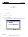
Starting the MCUez Linker
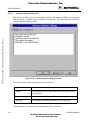
When the linker is started, a standard Tip of the Day window containing features about the
linker is displayed.
Figure 2-1. MCUez Linker Tip of The Day Window
MCUEZLNK0508/D
2-1
For More Information On This Product,
Go to: www.freescale.com
Freescale Semiconductor, Inc.
USER INTERFACE
Click Next Tip to view more information about the linker. Click Close to close the Tip of the
Day dialog. If you do not want to view the Tip of the Day window when the linker is started,
uncheck Show Tips on StartUp.
To re-enable the automatic display, choose Help|Tip of the Day .... The Tip of the Day dialog
will display and you can check Show Tips on StartUp.
2.2.2
Linker Graphical Interface
Freescale Semiconductor, Inc...
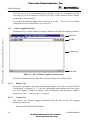
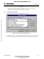
Starting the MCUez Linker without specifying a filename will display the following window.
Menu Bar
Tool Bar
Content Area
Status Bar
Figure 2-2. MCUez Linker Graphical User Interface
The Linker Window provides a Menu Bar, Tool Bar, Content Area, and Status Bar.
2.2.2.1
Window Title
The window title displays the linker name and project name. If no project is loaded, “Default
Configuration” is displayed. A “*” after the configuration name indicates that some values
have been changed. Changes in options, editor configuration, and appearance (Window
position, size, font, ...) will cause the “*” to appear.
2.2.2.2
Content Area
The Content Area displays logging information about the link session. This logging
information consists of:
•
The name of the PRM file being linked.
2-2
MCUEZLNK0508/D
For More Information On This Product,
Go to: www.freescale.com
Freescale Semiconductor, Inc.
USER INTERFACE
•
The name (including full path) of the files building the application.
•
Thle list of errors, warnings, and information messages.
When a file name is dropped into the Linker window content area, the corresponding file is
either loaded as configuration data or linked. It is loaded as configuration data if the file
extension is “ini”. If not, the file is linked with the current option settings (See Specifying the
Input File below).
Freescale Semiconductor, Inc...
The Linker window content area can have context information consisting of two items:
•
a file name including a position inside of a file
•
a message number
File context information is available for all output lines where a file name is displayed. If a file
context is available for a line, double-clicking on this line opens the appropriate file in the
editor specified in your MCUez configuration. Double-clicking the right mouse button alos
opens a context menu. The menu contains an “Open ..” entry if a file context is available. If a
file can not be opened although a context menu entry is present, see the section Editor Settings
Dialog.
Note that under Win32s the context menu is not available. If a file can not be opened although
a context menu entry is present, see the section on “Editor Settings” below.
The message number is available for any message output. To open the corresponding entry in
the help file, do one of the following.
•
Select one line of the message and press F1. If the selected line does not have a message
number, the main help is displayed.
•
Press Shift-F1 and then click on the message text. If the clicked point does not have a
message number, the main help is displayed.
•
Click the right mouse button at the message text and select “Help on ...”. This entry is only
available if a message number is available. The context menu is not available under
Win32s.
Once a link session has completed, an Error Feedback can be performed automatically by
double clicking on the message in the content area. To allow Error Feedback, the desired
editor must be configured (See Error Feedback below).
MCUEZLNK0508/D
2-3
For More Information On This Product,
Go to: www.freescale.com
Freescale Semiconductor, Inc.
USER INTERFACE
2.2.2.3
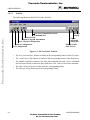
Tool Bar
The following illustrates the MCUez Linker Tool Bar.
Freescale Semiconductor, Inc...
Lists Last Command Executed
(command line)
Context Help
Displays Program Information
Saves Current Configuration
Loads a Configuration
New Configuration
Message
Setting
Opens
Advanced
Dialog Box
Link: Executes
Link Process
Figure 2-3. MCUez Linker Tool Bar
•
The New, Load and Save buttons are linked to the corresponding entries of the File menu.
•
The ? and Context Help buttons are linked to the corresponding entries of the Help menu.
•
The editable combo box contains a list of the last commands executed. Once a command
line has been selected or entered in this combo box, click Link to execute this command.
•
The Open Advanced Options button opens the corresponding dialog.
•
The Message Setting button opens the corresponding dialog.
2-4
MCUEZLNK0508/D
For More Information On This Product,
Go to: www.freescale.com
Freescale Semiconductor, Inc.
USER INTERFACE
2.2.2.4
Status Bar
Freescale Semiconductor, Inc...
Point at a menu entry or button in the Tool Bar to display the corresponding description in the
message field. The following illustration shows the MCUez Linker Status Bar.
Message Field
Status Bar
Current Time
Figure 2-4. MCUez Linker Status Bar
MCUEZLNK0508/D
2-5
For More Information On This Product,
Go to: www.freescale.com
Freescale Semiconductor, Inc.
USER INTERFACE
2.2.2.5
Linker Menu Bar
The following entries are available in the Menu Bar:
Freescale Semiconductor, Inc...
Menu entry
2.2.2.6
Description
File
Linker Configuration File management.
Linker
Linker option settings.
View
Linker Window settings.
Help
Standard Windows Help menu.
File Menu
A typical linker Configuration File contains the following information:
•
The linker option settings specified in the Advanced Options Settings and Message
Settings dialogs.
•
List of commands executed.
•
Window position, size and font used.
•
The editor associated with the Linker.
Linker Configuration information is stored in section [ELF_LINKER] in the specified
configuration file.
Configuration Files are ASCII files with a .ini extension. You can define as many of these
files as you need for any given project. You can switch between different Configuration Files
by choosing File|Load Configuration and File|Save Configuration in the Linker Menu Bar, or
by clicking the corresponding tool bar buttons.
•
Choose File|Linker to open a standard Open File dialog box that displays a list of all
.PRM files in the project directory. Select the input file to be linked and click OK.
•
Choose File|New/Default Configuration to reset the linker settings to the default values.
Default linker options are specified in the Command Line Options chapter in the Linker
manual.
•
Choose File|Load Configuration to open the Open File dialog box and display a list of all
.INI files in the project directory. Select a configuration file containing the data to be
loaded.
•
Choose File|Save Configuration to store the current settings in the configuration file
specified on the title bar.
•
Choose File|Save Configuration as ... to open a standard Save As dialog box and display a
list of all .INI files. Specify the name or location of the configuration file to store the
current settings. Click OK.
2-6
MCUEZLNK0508/D
For More Information On This Product,
Go to: www.freescale.com
Freescale Semiconductor, Inc.
Freescale Semiconductor, Inc...
USER INTERFACE
•
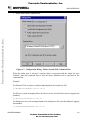
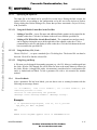
Choose File|Configuration ... to specify an editor to be used for error feedback and
information to be saved in the configuration file.
•
Global Editor (Configured by the Shell)
Figure 2-5. Configuration Dialog - Global Editor
This entry is enabled when an editor is configured in the [Editor] section of the global initialization file "MCUTOOLS.INI" .
MCUEZLNK0508/D
2-7
For More Information On This Product,
Go to: www.freescale.com
Freescale Semiconductor, Inc.
USER INTERFACE
Freescale Semiconductor, Inc...
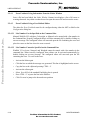
•
Local Editor (Configured by the Shell)
Figure 2-6. Configuration Dialog - Local Editor
This entry is enabled when an editor is configured in the local configuration file; usually
"project.ini" in the project directory.
The Global and Local Editor can be configured with the Shell (see separate Manual for the
Shell Tool).
2-8
MCUEZLNK0508/D
For More Information On This Product,
Go to: www.freescale.com
Freescale Semiconductor, Inc.
USER INTERFACE
Freescale Semiconductor, Inc...
•
Editor started with Command Line
Figure 2-7. Configuration Dialog - Editor Started With Command Line
When this editor type is selected, a separate editor is associated with the Linker for error
feedback. Enter the command line to start the editor. Modifiers can be specified on the
command line.
Example:
For Winedit 32-bit version use (with an adapted path to the winedit.exe file)
C:\WinEdit32\WinEdit.exe %f /#:%l
For Write.exe (with an adapted path to the Write.exe file, note that Write does not support line
numbers).
C:\Winnt\System32\Write.exe %f
For Motpad.exe use (with an adapted path to the Motpad.exe file, note that Motpad supports
line number).
C:\TOOLS\MOTPAD\MOTPAD.exe %f::%l
MCUEZLNK0508/D
2-9
For More Information On This Product,
Go to: www.freescale.com
Freescale Semiconductor, Inc.
USER INTERFACE
Freescale Semiconductor, Inc...
•
Editor started with DDE
Figure 2-8. Configuration Dialog - Editor Started With DDE
Enter the service, topic and client name to be used for a DDE connection to the editor. All
entries can have modifiers for file name and line number as explained below.
Example:
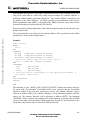
For Microsoft Developer Studio use the following setting :
Service Name : "msdev"
Topic Name : "system"
ClientCommand : "[open(%f)]"
•
Modifiers
When either entry ‘Editor Started with the Command line’ or ‘Editor started with DDE’ is
selected, the configurations may contain some modifiers to tell the editor which file to open
and at which line.
•
The %f modifier refers to the file name (including path) where the error has been detected.
•
The %l modifier refers to the line number where the message has been detected.
2-10
MCUEZLNK0508/D
For More Information On This Product,
Go to: www.freescale.com
Freescale Semiconductor, Inc.
USER INTERFACE
The format from the editor command depends on the syntax used to start the editor. Some
modifiers can be specified in the editor command line. Please check your editor manual to
define the command line which should be used to start the editor.
2.2.2.6.1
Important remarks
Freescale Semiconductor, Inc...
Caution should be taken using %l. This modifier can only be used with an editor that can be
started with a line number as a parameter. Editors such as WinEdit version 3.1 or lower,
Notepad, and Motpad do not allow this kind of parameter. This kind of editor can be started
using the file name as a parameter. Choose Go to to jump to the line containing the error.
The Command Line looks like:
C:\WINAPPS\WINEDIT\Winedit.EXE %f
Check your editor manual to define the Command Line used to start the editor.
MCUEZLNK0508/D
2-11
For More Information On This Product,
Go to: www.freescale.com
Freescale Semiconductor, Inc.
USER INTERFACE
NOTE
If you are using a word processing editor (Microsoft Word, Wordpad, ...),
save your input file as an ASCII text file.
2.2.2.6.2
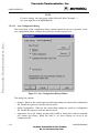
Save Configuration Dialog
Freescale Semiconductor, Inc...
The second page of the configuration dialog contains options for the save operation. In the
save configuration dialog, configure the parts to be stored in a project file.
Figure 2-9. Save Configuration Dialog Window
This dialog box contains:
•
Options: When set, the current option and message settings are stored in the configuration
file. Disable this option to retain the data last saved.
•
Editor Configuration: When set, the current editor settings are stored in a configuration
file. Disable this option to retain the data last saved.
•
Appearance: Saves the window position (only loaded at startup time) and the command
line content and history. When this mark is set, these settings are saved in the
configuration file.
2-12
MCUEZLNK0508/D
For More Information On This Product,
Go to: www.freescale.com
Freescale Semiconductor, Inc.
USER INTERFACE
NOTE
By disabling selective options only parts of a configuration file can be
written. For example when the suitable editor is found, the save option
mark can be removed. Then future save commands will not modify the
editor setting.
Freescale Semiconductor, Inc...
•
Save on Exit: If set, the Linker will write the configuration on exit. No confirmation
prompt will appear. If options have changed, the Linker will not write the configuration
unless this option is set.
NOTE
Almost all settings are stored in the configuration file, except for the recently
used configuration list and all settings in this dialog.
These settings are stored in the [ELF_LINKER] section of the MCUTOOLS.INI
initialization file.
NOTE
Linker configurations can coexist in the same file as the project
configuration of the shell and other MCUez tools. When an editor is
configured by the shell, the linker can read the content from the project file,
if present. The project configuration file of the shell is named project.ini.
This file name is therefore also suggested (but not mandatory) to the
Linker.
2.2.2.7
Linker Menu
This menu allows you to customize the linker and set or reset linker options. Choose
Linker|Options to define the options for linking an input file (See section 2.2.3.9, Advanced
Options Dialog Box, in this chapter).
2.2.2.8
View Menu
This menu enables you to customize the Linker Window. You can define whether to display or
hide the Status Bar or Tool Bar. You can also define the font used in the window or clear the
window.
•
Choose View|Tool Bar to switch on/off the Linker Window Tool Bar.
•
Choose View|Status Bar to switch on/off the Linker Window Status Bar.
•
Choose View|Log ... to customize the output in the Linker Window Content Area.
•
Choose View|Log ...|Change Font to open a standard Font Selection dialog box. Options
selected in this dialog are applied to the Linker Window Content Area.
•
Choose View|Log ...|Clear Log to clear the Linker Window Content Area.
MCUEZLNK0508/D
2-13
For More Information On This Product,
Go to: www.freescale.com
Freescale Semiconductor, Inc.
USER INTERFACE
2.2.2.9
Advanced Options Dialog Box
Freescale Semiconductor, Inc...
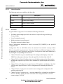
This dialog box allows you to set/reset linker options. The options available are arranged in
different groups. A register card is available for each group. The following figure shows the
Advanced Options Dialog window.
Figure 2-10. Advanced Options Dialog Window
The content of the list box depends on the selected sheet:
Option Group
Description
Output
Lists options related to generated output files (type of files to
be generated).
Input
Lists options related to input files.
Messages
Lists options controlling generation of error messages.
A linker option is set when the corresponding check box is checked.
2-14
MCUEZLNK0508/D
For More Information On This Product,
Go to: www.freescale.com
Freescale Semiconductor, Inc.
USER INTERFACE
NOTE
When options requiring additional parameters are selected, an edit box or
another window can be opened to set the additional parameters.
2.2.3
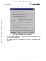
Message Settings Dialog Box
Freescale Semiconductor, Inc...
The following figure shows the Message Settings Dialog window.
Figure 2-11. Message Settings Dialog Window
This dialog box allows you to map messages to a different message class. A sheet is available
for each error message class and the content of the list box depends on the selected sheet.
MCUEZLNK0508/D
2-15
For More Information On This Product,
Go to: www.freescale.com
Freescale Semiconductor, Inc.
USER INTERFACE
The table below identifies and defines each message group.
Table 2-1. Message Group Definitions
Freescale Semiconductor, Inc...
Message Group
Description
Disabled
Lists all disabled messages. Messages displayed in the list box will
not be generated by the Linker.
Information
Lists all information messages. Information messages depict action
taken by the Linker.
Warning
Lists all warning messages. When such a message is generated,
linking continues and an absolute file is generated.
Error
Lists all error messages. When such a message is generated, linking
of the input application continues but no absolute file will be
generated.
Fatal
Lists all fatal error messages. When such a message is generated,
linking stops immediately.
Each message has its own character (‘L’ for Linker message) followed by a 4-5 digit number.
This number allows an easy search for the message both in the manual or online help.
2.2.3.1
Changing the Class Associated With a Message
You can configure your own mapping of messages in the different classes by using one of the
buttons located on the right hand side of the dialog box. Each button refers to a message class.
To change the class associated with a message, select the message in the list box and click the
button associated with the class where you want to move the message.
Example
To define the message ‘L1201: No stack defined' (warning message) as an error message:
1. Click the Warning sheet to display the list of all warning messages in the list box.
2. Click on the string ‘L1201: No stack defined' in the list box to select the message.
3. Click Error to define this message as an error message.
Click on the 'OK' button to validate the modification to the error message mapping. If you
close the dialog box with the 'Cancel' button, the previous message mapping remains valid.
2-16
MCUEZLNK0508/D
For More Information On This Product,
Go to: www.freescale.com
Freescale Semiconductor, Inc.
USER INTERFACE
2.2.3.2
Specifying the Input File
The input file to be linked can be specified in several ways. During the link session, the
options will be set according to the configuration set by the user in the Advanced Options
Settings dialog box. Before linking a file, ensure that you have associated a Project Directory
with your linker.
Freescale Semiconductor, Inc...
2.2.3.2.1
Using the Editable Combo Box in the Tool Bar
•
Linking a New File - A new file name and additional linker options can be entered in the
editable combo box. Click the Link button in the tool bar to link the specified file.
•
Linking a File Which Has Already Been Linked - The command executed previously
can be displayed using the arrow on the right side of the editable combo box. Click a
command line to select it and display it in the combo box. Click the Link button in the tool
bar to assemble the specified file.
2.2.3.2.2
Using the Entry File | Link ...
Choose File|Link ..., to open a standard Open File dialog box. The desired file can then be
browsed. Click OK to link the selected file.
2.2.3.2.3
Using Drag and Drop
A file name can be dragged from another program (e.g., the File Manager) and dropped into
the Linker Window. The dropped file will be linked as soon as the mouse button is released in
the Linker Window. A dragged file with a .ini extension is considered to be a configuration file
and it is loaded and not linked. To link a parameter file with a .ini extension use another
method.
2.2.4
Error Feedback
After a parameter file has been linked, you can detect error or warning locations with the
following error message format.
‘>> <F ile Nam e>, lin e < lin e n umb er>, co l < col umn nu mber >, pos
<absolute position in file>
<Portion of code generating the problem>
<message class> <message number>: <Message string>‘
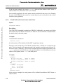
Example
>> in "placemen\tstpla8.prm", line 23, col 0, pos 668
fpm_data_sec INTO MY_RAM2;
END
ERROR L1110: MY_RAM2 appears twice in PLACEMENT block
MCUEZLNK0508/D
2-17
For More Information On This Product,
Go to: www.freescale.com
Freescale Semiconductor, Inc.
USER INTERFACE
2.2.4.1
Error Feedback Using Information From the Linker Window
Once a file has been linked, the Linker Window Content Area displays a list of all errors or
warnings detected. Any editor can then be used to open the source file and correct the errors.
2.2.4.2
Error Feedback Using a User-Defined Editor
The editor for Error Feedback must first be configured using either the MCUez Shell or the
Configuration dialog box.
Freescale Semiconductor, Inc...
2.2.4.2.1
Line Number Can be Specified on the Command Line
Motpad, WinEdit V95 or higher, Codewright, or Motpad can be started with a line number in
the command line. Properly configured editors will start automatically by double clicking on
an error message. The configured editor will start and open the file containing the error and
place the cursor on the line where the error occurred.
2.2.4.2.2
Line Number Cannot be Specified on the Command Line
WinEdit V31 or lower, Notepad, and Wordpad cannot be started with a line number in the
command line. When correctly configured, these editors can be activated automatically by
double clicking on an error message. The configured editor will start and open the file
containing the error. To scroll to the error:
•
Activate the linker again
•
Click the line on which the message was generated. This line is highlighted on the screen.
•
Copy the line to the clipboard pressing CTRL + C
•
Activate the editor again.
•
Select Search|Find, the standard Find dialog box is opened.
•
Press CTRL + V to paste the line in the Edit box.
•
Click Forward to jump to the detected error position.
2-18
MCUEZLNK0508/D
For More Information On This Product,
Go to: www.freescale.com
Freescale Semiconductor, Inc.
ENVIRONMENT VARIABLES
CHAPTER 3
ENVIRONMENT VARIABLES
Freescale Semiconductor, Inc...
3.1
INTRODUCTION
This chapter describes environment variables used by the MCUez Linker. Some of the
environment variables are also used by other tools (e.g. Macro Assembler, Compiler, ...).
Consult their respective manuals for more information.
3.2
SETTING PARAMETERS
Various linker parameters may be set with environment variables. The syntax is:
KeyName=ParamDefinition
NOTE
No blanks are allowed in the definition of an environment variable.
Example:
GENPATH=C:\INSTALL\LIB;D:\PROJECTS\TESTS;\usr\local\lib;
These parameters may be defined in several ways:
•
Using system environment variables supported by your operating system.
•
Putting the definitions in a file called DEFAULT.ENV (.hidefaults for UNIX) in the
project directory.
•
Putting the definitions in a file given by the value of the system environment variable
ENVIRONMENT.
NOTE
The default directory mentioned above can be set via the system environment
variable DEFAULTDIR.
When looking for an environment variable, all programs first search the system environment,
then the DEFAULT.ENV (.hidefaults for UNIX) file and finally the global environment file
given by ENVIRONMENT. If no definition can be found, a default value is assumed.
MCUEZLNK0508/D
3-1
For More Information On This Product,
Go to: www.freescale.com
Freescale Semiconductor, Inc.
ENVIRONMENT VARIABLES
3.3
PATH VARIABLES
Most environment variables contain path lists indicating where to look for files. A path list is
a list of directory names separated by semicolons; as follows:
DirSpec;DirSpec;DirSpec
*DirectoryName
Example:
Freescale Semiconductor, Inc...
GENPATH=C:\INSTALL\LIB;D:\PROJECTS\TESTS;\usr\local\lib;
If a directory name is preceded by an asterisk ("*"), the programs recursively search the
whole directory tree for a file, not just the given directory. Directories are searched in the
order they appear in the path list.
Example:
LIBPATH=*C:\INSTALL\LIB
NOTE
Some DOS/UNIX environment variables (like GENPATH, LIBPATH, etc.) are
used. For further details refer to “Environment” chapter.
We strongly recommend working with MCUez Shell and setting the environment by means of
a DEFAULT.ENV file in your project directory. This project directory can be set in the MCUez
Shell 'Configure...' dialog box. This way, you can have different projects in different
directories, each with its own environment.
For some environment variables a synonym also exists. These synonyms may be used for
older releases of the linker and will be removed in the future.
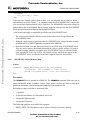
3.3.1
LINKOPTIONS
Synonym:
None
Syntax:
"LINKOPTIONS=" {<option>}.
Arguments:
<option>: Linker command line option
Description:
If this environment variable is set, the linker appends its contents to its
command line each time a file is linked. It can be used to globally
specify certain options that should always be set, so you don’t have to
specify them each time a file is linked.
Example:
LINKOPTIONS=-W2
See also:
Linker options
3-2
MCUEZLNK0508/D
For More Information On This Product,
Go to: www.freescale.com
Freescale Semiconductor, Inc.
ENVIRONMENT VARIABLES
Freescale Semiconductor, Inc...
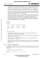
3.3.2
GENPATH
Synonym:
HIPATH
Syntax:
"GENPATH=" {<path>}.
Arguments:
<path>: Paths separated by semicolons, without spaces.
Description:
The linker will look for the PRM file in the project directory, then in the
directories listed in the environment variable GENPATH. The object
and library files specified in the linker PRM file are searched for in the
project directory, then in directories listed in the environment variable
OBJPATH and finally in directories specified in GENPATH.
NOTE
If a directory specification in this environment variable starts with an asterisk
(“*”), the whole directory tree is searched recursively, i.e. all subdirectories are
also searched. Within one level in the tree, the search order of the subdirectories
is indeterminate (not valid for Win32).
3.3.3
3.3.4
Example:
GENPATH=\obj;..\..\lib;
See also:
None
OBJPATH
Synonym:
None
Syntax:
"OBJPATH=" {<path>}.
Arguments:
<path>: Paths separated by semicolons, without spaces.
Description:
When this environment variable is defined, the linker searches the
project directory for the object and library files specified in the linker
PRM file. The linker then searches the directories listed in the
environment variable OBJPATH and GENPATH.
Example:
OBJPATH=\sources\bin;..\..\headers;\usr\local\bin
ABSPATH
Synonym:
None
Syntax:
"ABSPATH=" {<path>}.
Arguments:
<path>: Paths separated by semicolons, without spaces.
Description:
When this environment variable is defined, the linker will store the
absolute files it produces in the first directory specified. If ABSPATH is
not set, the generated absolute files will be stored in the directory where
the parameter file was found.
MCUEZLNK0508/D
3-3
For More Information On This Product,
Go to: www.freescale.com
Freescale Semiconductor, Inc.
ENVIRONMENT VARIABLES
Freescale Semiconductor, Inc...
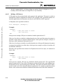
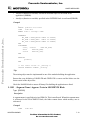
3.3.5
Example:
ABSPATH=\sources\bin;..\..\headers;\usr\local\bin
See also:
None
TEXTPATH
Synonym:
None
Syntax:
"TEXTPATH=" {<path>}.
Arguments:
<path>: Paths separated by semicolons, without spaces.
Description:
When this environment variable is defined, the linker will store the
MAP file it produces in the first directory specified. If TEXTPATH is
not set, the generated MAP file will be stored in the directory where the
PRM file was found.
Example:
TEXTPATH=\sources ..\..\headers;\usr\local\txt
See also:
None
3-4
MCUEZLNK0508/D
For More Information On This Product,
Go to: www.freescale.com
Freescale Semiconductor, Inc.
ENVIRONMENT VARIABLES
Freescale Semiconductor, Inc...
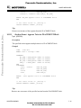
3.3.6
SRECORD
Synonym:
None
Syntax:
SRECORD=<RecordType>.
Arguments:
<Record Type>: Force the type for the Motorola S record that must be
generated. This parameter value can be ‘S1’, ‘S2’ or ‘S3’.
Description:
When this environment variable is defined, the linker will generate a
Motorola S file containing records from the specified type (S1 records
when S1 is specified, S2 records when S2 is specified and S3 records
when S3 is specified).
NOTE
If the environment variable SRECORD is set, it is the user responsibility to
specify the appropriate S record type. If you specify S1 while your code is
loaded above 0xFFFF, the Motorola S file generated will not be correct, as the
addresses will all be truncated to 2-byte values.
NOTE
When this variable is not set, the type of S record generated will depend on the
size of the address loaded. If the address can be coded on two bytes, a S1 record
is generated. If the address is coded on three bytes, a S2 record is generated.
Otherwise, a S3 record is generated.
3.3.7
Example:
SRECORD=S2
See also:
None
ERRORFILE
Synonym:
None.
Syntax:
ERRORFILE=<filename>
Arguments:
<filename>: File name with format specifiers.
Description:
The environment variable ERRORFILE specifies the name of the error
file (used by the Linker).
Possible format specifiers are:
%n: Substitute with the file name, without the path.
%p: Substitute with the path of the source file.
%f: Substitute with the full file name, i. e. with the path and name
(same as %p%n).
In case of an illegal error file name, a notification box is displayed.
MCUEZLNK0508/D
3-5
For More Information On This Product,
Go to: www.freescale.com
Freescale Semiconductor, Inc.
ENVIRONMENT VARIABLES
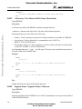
Example:
ERRORFILE=MyErrors.err
Lists all errors in the file “MyErrors.err” in the project directory.
ERRORFILE=\tmp\errors
Lists all errors in the file “errors” in the directory \tmp.
ERRORFILE=%f.err
Freescale Semiconductor, Inc...
Lists all errors in a file with the same name as the source file, but with
extension .err. The error file is placed in the same directory as the
source file. For example, if we link a file \sources\test.prm, an error list
file \sources\test.err will be generated.
ERRORFILE=\dir1\%n.err
For a source file test.prm, an error list file \dir1\test.err will be
generated.
ERRORFILE=%p\errors.txt
For a source file \dir1\dir2\test.prm, an error list file \dir1\dir2\errors.txt
will be generated.
If the environment variable ERRORFILE is not set, the errors are
written to the default error file. The default error file name is dependent
upon how the assembler is configured and started. If a file name is
provided in the assembler command line, errors are written to the
EDOUT file (to the name-specified file) in the project directory. If no
file name is provided, errors are written to the ERR.TXT file in the
project directory.
Example:
Another example shows the usage of this variable to support correct
error feedback with the WinEdit Editor which looks for an error file
called EDOUT:
Installation directory: E:\INSTALL\PROG
Project sources: D:\MEPHISTO
Common Sources for projects: E:\CLIB
Entry in default.env (D:\MEPHISTO\DEFAULT.ENV):
ERRORFILE=E:\INSTALL\PROG\EDOUT
Entry in WINEDIT.INI (in Windows directory):
OUTPUT=E:\INSTALL\PROG\EDOUT
See also:
None
3-6
MCUEZLNK0508/D
For More Information On This Product,
Go to: www.freescale.com
Freescale Semiconductor, Inc.
FILES
CHAPTER 4
FILES
Freescale Semiconductor, Inc...
4.1
INTRODUCTION
The following sections describe the files used and generated by the MCUez Linker.
4.2
PARAMETER FILE: INPUT
The linker takes any file as input. No special extension is required. However, we suggest that
parameter file names have the extension .prm. Parameter files will be searched first in the
project directory and then in the GENPATH directories. The parameter file must be an ASCII
text file.
4.3
ABSOLUTE FILES: OUTPUT
After a successful link session, the linker generates an absolute file containing the target code
as well as some debugging information. This file is written to the directory given in the
environment variable ABSPATH. If the variable contains more than one path, the absolute file
is written to the first directory specified. If this variable is not set, the absolute file is written to
the directory where the parameter file was found. Absolute files always get the extension
.abs.
4.4
MOTOROLA S FILES: OUTPUT
After a successful link session, the linker generates a Motorola S record file, which can be
burnt into an EPROM. This file contains information stored in all the READ_ONLY sections
in the application. The extension for the generated Motorola S record file depends on the
setting from the SRECORD variable.
•
If SRECORD = S1, the Motorola S record file gets the extension .s1.
•
If SRECORD = S2, the Motorola S record file gets the extension .s2.
•
If SRECORD = S3, the Motorola S record file gets the extension .s3.
•
If SRECORD is not set, the Motorola S record file gets the extension .sx.
This file is written to the directory given in the environment variable ABSPATH. If the variable
contains more than one path, the S record file is written to the first directory specified. If this
variable is not set, the S record file is written to the directory where the parameter file was
found.
MCUEZLNK0508/D
4-1
For More Information On This Product,
Go to: www.freescale.com
Freescale Semiconductor, Inc.
FILES
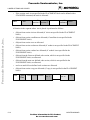
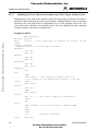
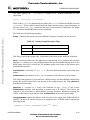
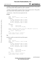
4.5
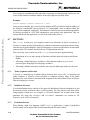
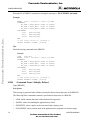
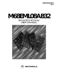
MAP FILES
After a successful link session, the linker generates a MAP file containing information about
the link process (see figure below). This file is written to the directory given in the
environment variable TEXTPATH. If the variable contains more than one path, the MAP file is
written to the first directory specified. If this variable is not set, the MAP file is written to the
directory where the parameter file was found. MAP files always get the extension .map.
Freescale Semiconductor, Inc...
.prm
1.current dir
2.GENPATH
“.o” 1.current dir
“.lib” 2. OBJPATH
“.abs”
3.GENPATH
Linker
ERRORFILE
.abs
.sx
1.ABSPAT
H
2.Source
.map
1.TEXTPAT
H
2.Source
ERR.TXT
or
EDOUT
Figure 4-1. Link Process Conceptual Diagram
4-2
MCUEZLNK0508/D
For More Information On This Product,
Go to: www.freescale.com
Freescale Semiconductor, Inc.
LINKER OPTIONS AND ISSUES
CHAPTER 5
LINKER OPTIONS AND ISSUES
Freescale Semiconductor, Inc...
5.1
INTRODUCTION
The MCUez Linker offers a number of options to control linker operation. Options are
composed of a minus/dash (‘-’) followed by one or more letters or digits. Anything not
starting with a dash/minus is assumed to be the name of a parameter file to be linked. Linker
options may be specified on the command line or in the LINKOPTIONS variable. Typically,
each option is specified once per linking session.
NOTE
Arguments for an option must not exceed 128 characters.
Command line options are not case sensitive. For example, "–o=test.abs" is the same as
"–O=TEST.ABS".
When the LINKOPTIONS variable is set, the linker appends the variable settings to its
command line each time a new file is linked. This variable can be used to globally specify
options that should always be set. The remainder of this section describes each of the linker
options. The options are listed in alphabetical order and divided into the following sections.
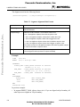
Table 5-1. MCUez Linker Options Descriptions
Topic
Description
Syntax
Specifies the syntax of the option in an EBNF format.
Arguments
Describes and lists optional and required arguments.
Default
Shows the default setting for the option.
Description
Provides a detailed description of the option and how to use it.
Example
Gives an example of usage and effects where possible. Linker
settings, source code and/or Linker PRM files are displayed where
applicable. The examples show an entry in the default.env file
for PC or in the .hidefaults for UNIX.
See also
Names related options.
MCUEZLNK0508/D
5-1
For More Information On This Product,
Go to: www.freescale.com
Freescale Semiconductor, Inc.
LINKER OPTIONS AND ISSUES
Freescale Semiconductor, Inc...
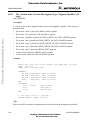
5.2
-E LINKER OPTION
-E:
Define Application Entry Point
Syntax:
"-E=" <FunctionName>.
Arguments:
<FunctionName>: Name of the function, which is considered to be the
entry point in the application.
Default:
none.
Description:
This option specifies the name of the application entry point. When the
entry point is located in an assembly object file, the corresponding
symbol must be a global symbol (Specified in an XDEF directive).
Example:
LINKOPTIONS=-E=entry
This is the same as using the command:
INIT entry
in the PRM file
See also:
5.3
Command INIT
-O LINKER OPTION
-O:
Define Absolute File Name
Syntax:
"-O=" <FileName>
Arguments:
<fileName>: Name of the absolute file to be generated by the linking
session.
Default:
None.
Description:
This option defines the name of the ABS file that must be generated.
Example:
LINKOPTIONS=-O=test.abs
This is the same as using the command:
LINK test.abs
in the PRM file
See also:
Command LINK
5-2
MCUEZLNK0508/D
For More Information On This Product,
Go to: www.freescale.com
Freescale Semiconductor, Inc.
LINKER OPTIONS AND ISSUES
Freescale Semiconductor, Inc...
5.4
-M LINKER OPTION
-M:
Generate MAP File
Syntax:
"-M"
Arguments:
None.
Default:
None.
Description:
This option forces generation of a MAP file after a successful link
session.
Example:
LINKOPTIONS=-M
This is the same as using the command:
MAPFILE ALL
in the PRM file
See also:
5.5
Command MAPFILE
-S LINKER OPTION
-S:
Do not generate DWARF Information
Syntax:
"-S"
Arguments:
None.
Default:
None.
Description:
This option disables the generation of DWARF sections in the absolute
file. This will reduce the amount of memory used on your PC.
Example:
LINKOPTIONS=-S
See also:
None
NOTE
If the absolute file does not contain DWARF information, you will not be able to
debug it.
MCUEZLNK0508/D
5-3
For More Information On This Product,
Go to: www.freescale.com
Freescale Semiconductor, Inc.
LINKER OPTIONS AND ISSUES
Freescale Semiconductor, Inc...
5.6
-V LINKER OPTION
-V:
Prints the Linker Version
Syntax:
"-V".
Arguments:
None.
Default:
None.
Description:
Prints the Linker version and the project directory.
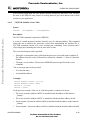
Example:
-V produces the following list:
Directory: D:\mcuez\PROG
MCUez ELF Linker V-1.0.29
CCPP User Interface Module, V-1.0.4, Date Jul 18 1997
See also:
None.
NOTE
This option can be used to determine the project directory.
5.7
5.8
-W1 LINKER OPTION
-W1:
No Information Messages
Syntax:
"-W1"
Arguments:
None.
Default:
None.
Description:
Suppresses all INFORMATION messages; WARNING and ERROR
messages are printed.
Example:
LINKOPTIONS=-W1
See also:
None
-W2 LINKER OPTION
-W2:
No Information and Warning Messages
Syntax:
"-W2".
Arguments:
None.
Default:
None.
Description:
Suppresses all INFORMATION and WARNING messages, only
ERRORs are printed.
Example:
LINKOPTIONS=-W2
See also:
None
5-4
MCUEZLNK0508/D
For More Information On This Product,
Go to: www.freescale.com
Freescale Semiconductor, Inc.
LINKER OPTIONS AND ISSUES
5.9
LINKING ISSUES
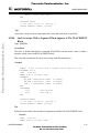
The following sections identify specific application issues for the MCUez Linker.
5.9.1
Object Allocation
Object allocation is performed through the SEGMENTS and PLACEMENT blocks.
Freescale Semiconductor, Inc...
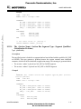
5.9.1.1
The SEGMENTS Block
The segments block is optional. It increases readability of the linker input file by assigning
meaningful names to contiguous memory areas on the target board. Memory within such an
area share common attributes:
•
Qualifier
•
Alignment Rules
•
Filling Character
Two types of segments can be defined:
•
Physical Segments
•
Virtual Segments
Physical segments are closely related to hardware memory areas.
For example, there may be one READ_ONLY segment for each bank of the target board
ROM area and another one covering the RAM area.
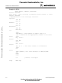
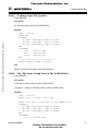
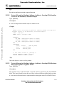
Example:
Using the small memory model you can define a segment for the RAM area and another one
for the ROM area.
LINK
test.abs
NAMES test.o startup.o END
SEGMENTS
RAM_AREA = READ_WRITE 0x00000 TO 0x07FFF;
ROM_AREA = READ_ONLY 0x08000 TO 0x0FFFF;
END
PLACEMENT
.data
INTO RAM_AREA;
.text
INTO ROM_AREA;
END
STACKSIZE 0x50
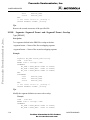
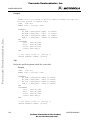
Using the banked memory model you can define a segment for the RAM area, another for the
non-banked ROM area, and one for each target processor bank.
LINK
NAMES
test.abs
test.o startup.o END
MCUEZLNK0508/D
5-5
For More Information On This Product,
Go to: www.freescale.com
Freescale Semiconductor, Inc.
LINKER OPTIONS AND ISSUES
Freescale Semiconductor, Inc...
SEGMENTS
RAM_AREA
= READ_WRITE 0x00000 TO 0x07FFF;
NON_BANKED_AREA = READ_ONLY 0x0C000 TO 0x0FFFF;
BANK0_AREA
= READ_ONLY 0x08000 TO 0x0BFFF;
BANK1_AREA
= READ_ONLY 0x18000 TO 0x1BFFF;
BANK2_AREA
= READ_ONLY 0x28000 TO 0x2BFFF;
END
PLACEMENT
.data
INTO RAM_AREA;
.init, .startData,
.rodata1,
NON_BANKED, .copy INTO NON_BANKED_AREA;
.text
INTO BANK0_AREA, BANK1_AREA,
BANK2_AREA;
END
STACKSIZE 0x50
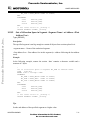
A physical segment may be split into several virtual segments, allowing a better structuring of
object allocation and taking advantage of some processor specific properties.
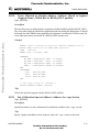
Example:
In the small memory model you can define a segment for the direct page area, another for the
rest of the RAM area, and another one for the ROM area.
LINK
NAMES
test.abs
test.o startup.o END
SEGMENTS
DIRECT_RAM = READ_WRITE 0x00000 TO 0x000FF;
RAM_AREA
= READ_WRITE 0x00100 TO 0x07FFF;
ROM_AREA
= READ_ONLY 0x08000 TO 0x0FFFF;
END
PLACEMENT
myRegister
INTO DIRECT_RAM;
.data
INTO RAM_AREA;
.text
INTO ROM_AREA;
END
STACKSIZE 0x50
5.9.1.1.1
Segment Qualifier
Different qualifiers are available for segments. The following table identifies and defines all
available qualifiers.
5-6
MCUEZLNK0508/D
For More Information On This Product,
Go to: www.freescale.com
Freescale Semiconductor, Inc.
LINKER OPTIONS AND ISSUES
Table 5-2. Segment Qualifier Descriptions
Freescale Semiconductor, Inc...
Qualifier
Meaning
READ_ONLY
Qualifies a segment, where read only access is allowed. Objects within
such a segment are initialized at application loading time.
READ_WRITE
Qualifies a segment, where read and write accesses are allowed. Objects
within such a segment are initialized at application startup. This is only
the case when linking a High Level Language (ANSI C or C++)
application.
NO_INIT
Qualifies a segment, where read and write accesses are allowed. Objects
within such a segment remain unchanged during application startup. This
qualifier may be used for segments refering to a battery backed RAM.
Sections placed in a NO_INIT segment should not contain an initialized
variable (variable defined as ‘int c = 8’).This is only the case when linking
a High Level Language (ANSI C or C++) application.
PAGED
Qualifies a segment, where read and write accesses are allowed. Objects
within such a segment remain unchanged during application startup.
Additionally, objects located in two PAGED segments may overlap. This
qualifier is used for memory areas, where some user defined page
switching mechanism is required. Sections placed in a NO_INIT segment
should not contain an initialized variable (variable defined as ‘int c =
8’).This is only the case when linking a High Level Language (ANSI C or
C++) application.
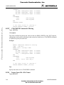
5.9.1.1.2
Segment Alignment
The default alignment rule depends on the processor and memory model used. The HC12,
HC08, and HC05 processors do not require alignment for code or data objects. One can
choose to define their own alignment rule for a segment. The alignment rule defined for a
segment block overrides the default alignment rules associated with the processor and
memory model.
MCUEZLNK0508/D
5-7
For More Information On This Product,
Go to: www.freescale.com
Freescale Semiconductor, Inc.
LINKER OPTIONS AND ISSUES
The alignment rule has the following format:
[defaultAlignment] {“[“ObjSizeRange”:”alignment”]”}
Table 5-3. Segment Alignment Rule Format
Freescale Semiconductor, Inc...
Item
Description
defaultAlignment
The alignment value for all objects that do not match the conditions of a range
defined afterward.
ObjSizeRange
Defines a certain condition. The condition has the form:
size : rule applies to objects, where size is equal to ‘size’
< size : rule applies to objects, where size is smaller than ‘size’
> size: rule applies to objects, where size is bigger than ‘size’
<= size: rule applies to objects, where size is smaller or equal to ‘size’
>= size: rule applies to objects, where size is bigger or equal to ‘size’
From size1 to size2: the rule applies to objects, where size is greater or equal
to ‘size1’ and smaller or equal to ‘size2’.
alignment
Defines the alignment value for objects matching the condition defined in the
current alignment block (enclosed in square brackets).
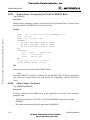
Example:
LINK
NAMES
test.abs
test.o startup.o END
SEGMENTS
DIRECT_RAM = READ_WRITE 0x00000 TO 0x000FF
ALIGN 2 [< 2: 1];
RAM_AREA
= READ_WRITE 0x00100 TO 0x07FFF
ALIGN [1:1] [2..3:2] [>=4:4];
ROM_AREA
= READ_ONLY 0x08000 TO 0x0FFFF;
END
PLACEMENT
myRegister
INTO DIRECT_RAM;
.data
INTO RAM_AREA;
.text
INTO ROM_AREA;
END
STACKSIZE 0x50
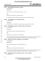
In previous example:
•
In segment DIRECT_RAM, objects whose size is 1 byte are aligned on byte boundary, all
other objects are aligned on 2-byte boundary.
5-8
MCUEZLNK0508/D
For More Information On This Product,
Go to: www.freescale.com
Freescale Semiconductor, Inc.
LINKER OPTIONS AND ISSUES
•
In segment RAM_AREA, 1 byte objects are aligned on byte boundary, objects equal to 2
or 3 bytes are aligned on 2-byte boundary, all other objects are aligned on 4-byte
boundary.
•
Default alignment rule applies to the ROM_AREA segment.
5.9.1.1.3
Segment Fill Pattern
Freescale Semiconductor, Inc...
The default fill pattern for code and data segments is the null character. You can define your
own fill pattern for a segment. The fill pattern definition in the segment block overrides the
default fill pattern. A fill pattern can be defined for the READ_WRITE memory area only
when linking a high level language (ANSI C, C++) application.
Example:
LINK
NAMES
test.abs
test.o startup.o END
SEGMENTS
DIRECT_RAM = READ_WRITE 0x00000 TO 0x000FF
FILL 0xAA;
RAM_AREA
= READ_WRITE 0x00100 TO 0x07FFF
FILL 0x22;
ROM_AREA
= READ_ONLY 0x08000 TO 0x0FFFF;
END
PLACEMENT
myRegister
INTO DIRECT_RAM;
.data
INTO RAM_AREA;
.text
INTO ROM_AREA;
END
STACKSIZE 0x50
In previous example:
5.9.1.2
•
In segment DIRECT_RAM, alignment bytes between objects are initialized with 0xAA.
•
In segment RAM_AREA, alignment bytes between objects are initialized with 0x22.
•
In segment ROM_AREA, alignment bytes between objects are initialized with 0x00.
PLACEMENT Block
The placement block allows you to physically place each section in a specific memory area
(segment). The sections specified in a PLACEMENT block may be linker-predefined sections
or user sections specified in one of the source files used to build the application.
A programmer may decide to organize data into sections:
• to enhance application structure
• to ensure that common purpose data is grouped together
• to take advantage of target processor specific addressing mode.
MCUEZLNK0508/D
5-9
For More Information On This Product,
Go to: www.freescale.com
Freescale Semiconductor, Inc.
LINKER OPTIONS AND ISSUES
5.9.1.2.1
Specifying a List of Sections
When several sections are specified on a PLACEMENT statement, the sections are allocated
in the sequence they are listed.
Example:
Freescale Semiconductor, Inc...
LINK
NAMES
test.abs
test.o startup.o END
SEGMENTS
RAM_AREA
= READ_WRITE 0x00100 TO 0x002FF;
STK_AREA
= READ_WRITE 0x00300 TO 0x003FF;
ROM_AREA
= READ_ONLY 0x08000 TO 0x0FFFF;
END
PLACEMENT
.data, dataSec1,
dataSec2
INTO RAM_AREA;
.text, myCode
INTO ROM_AREA;
.stack
INTO STK_AREA;
END
In previous example:
•
Inside of segment RAM_AREA, the objects defined in the .data section are allocated first,
then objects defined in section dataSec1 and finally objects defined in section dataSec2.
•
Inside of segment ROM_AREA, objects defined in the .text section are allocated, then
objects defined in section myCode.
NOTE
Since the linker is case sensitive, section names specified in the PLACEMENT
block must be valid predefined or user defined sections. Sections DataSec1 and
dataSec1 are different sections.
5.9.1.2.2
Specifying a List of Segments
When several segments are specified on a PLACEMENT statement, the segments are used in
the sequence they are listed. Allocation is performed for the first segment in the list, until this
segment is full. Then allocation continues for the next segment in the list, an so on until all
objects are allocated.
Example:
LINK
test.abs
NAMES test.o startup.o END
SEGMENTS
RAM_AREA
= READ_WRITE 0x00100 TO 0x002FF;
STK_AREA
= READ_WRITE 0x00300 TO 0x003FF;
NON_BANKED_AREA = READ_ONLY 0x0C000 TO 0x0FFFF;
5-10
MCUEZLNK0508/D
For More Information On This Product,
Go to: www.freescale.com
Freescale Semiconductor, Inc.
Freescale Semiconductor, Inc...
LINKER OPTIONS AND ISSUES
BANK0_AREA
= READ_ONLY 0x08000 TO 0x0BFFF;
BANK1_AREA
= READ_ONLY 0x18000 TO 0x1BFFF;
BANK2_AREA
= READ_ONLY 0x28000 TO 0x2BFFF;
END
PLACEMENT
.data
INTO RAM_AREA;
.stack
INTO STK_AREA;
.init, .startData,
.rodata1,
NON_BANKED, .copy INTO NON_BANKED_AREA;
.text
INTO BANK0_AREA, BANK1_AREA,
BANK2_AREA;
END
In previous example:
•
Functions implemented in section .text are allocated first in segment BANK0_AREA.
When memory for this segment is filled, allocation continues in segment
BANK_1_AREA, then in BANK2_AREA.
NOTE
Since the linker is case sensitive, segment names specified in the PLACEMENT
block must be valid segment names defined in the SEGMENTS block. Segments
Ram_Area and RAM_AREA are different segments.
5.9.2
Allocating User-Defined Sections
Not all sections need to be listed in the PLACEMENT block. Segments in which sections are
allocated, depends on the type of section.
•
Sections containing data are allocated next to the .data section.
•
Sections containing code, constant variables, or string constants are allocated next to the
.text section.
In the segment where .data is placed, allocation is performed as follows:
•
Objects from section .data are allocated
•
Objects from section .bss are allocated (if .bss is not specified in the PLACEMENT
block).
•
Objects from the first user defined data section, which is not specified in the
PLACEMENT block, are allocated.
•
Objects from the next user defined data section, which is not specified in the
PLACEMENT block, are allocated.
•
and so on until all user defined data sections are allocated.
MCUEZLNK0508/D
5-11
For More Information On This Product,
Go to: www.freescale.com
Freescale Semiconductor, Inc.
LINKER OPTIONS AND ISSUES
•
If the section .stack is not specified in the PLACEMENT block and is defined with a
STACKSIZE command, the stack is allocated.
.data
.bss
user data user data
section 1 section 2
user data
section n .stack
Freescale Semiconductor, Inc...
Allocation in the segment where .text is placed is performed as follows:
•
Objects from section .init are allocated (if .init is not specified in the PLACEMENT
block).
•
Objects from section .startData are allocated (if .startData is not specified in the
PLACEMENT block).
•
Objects from section .text are allocated.
•
Objects from section .rodata are allocated (if .rodata is not specified in the PLACEMENT
block).
•
Objects from section .rodata1 are allocated (if .rodata1 is not specified in the
PLACEMENT block).
•
Objects from the first user defined code section, which is not specified in the
PLACEMENT block, are allocated.
•
Objects from the next user defined code section, which is not specified in the
PLACEMENT block, are allocated.
•
and so on until all user defined code sections are allocated.
•
Objects from section .copy are allocated (if .copy is not specified in the PLACEMENT
block).
.init
user
.start- .text .rodata rodata1 sec. 1
Data
user
sec. n
5-12
.copy
MCUEZLNK0508/D
For More Information On This Product,
Go to: www.freescale.com
Freescale Semiconductor, Inc.
OPERATING PROCEDURES
CHAPTER 6
OPERATING PROCEDURES
Freescale Semiconductor, Inc...
6.1
INTRODUCTION
This chapter defines operating procedures for the MCUez Linker application.
6.2
INITIALIZING THE VECTOR TABLE
The following sections describe how to initialize the vector table. The vector table can be
initialized in the assembly source file or in the linker parameter file. Initialization in the PRM
file is recommended.
6.2.1
VECTOR Command
This command initializes the vector table. The syntax “VECTOR <Number>” is only valid
when the vector table starts at address 0x0000. The syntax VECTOR ADDRESS is valid in
any case. The size of entries in the vector table depends on the target processor. Different
syntaxes are available for the VECTOR command (Table 6-1).
Table 6-1. VECTOR Command Syntax
Command
Meaning
VECTOR ADDRESS 0xFFFE 0x1000
Indicates that the value 0x1000 must be stored at
address 0xFFFE
VECTOR ADDRESS 0xFFFE FName
Indicates that the address of the FName function must
be stored at address 0xFFFE
VECTOR ADDRESS 0xFFFE FName + 2
Indicates that the address of the FName function
incremented by 2 must be stored at address 0xFFFE
The last syntax may be very useful, when working with a common interrupt service routine.
6.2.1.1
Initializing the Vector Table in the Linker PRM File
Initializing the vector table from the PRM file allows you to initialize single entries in the
table (shown in the example below). The user can decide whether to initialize all entries in the
vector table or not. The labels or functions, must be inserted in the vector table and
implemented in the assembly source file. All labels must be published otherwise they cannot
be addressed in the linker PRM file.
MCUEZLNK0508/D
6-1
For More Information On This Product,
Go to: www.freescale.com
Freescale Semiconductor, Inc.
OPERATING PROCEDURES
Example for HC08:
Freescale Semiconductor, Inc...
XDEF IRQFunc, SWIFunc, ResetFunc
DataSec: SECTION
Data: DS.W 5 ; Each interrupt increments another element of table.
CodeSec: SECTION
; Implementation of the interrupt functions.
IRQ1Func:
LDA #0
BRA int
SWIFunc:
LDA #4
BRA int
ResetFunc:
LDA #8
BRA entry
int:
PSHH
LDHX #Data ; Load address of symbol Data in X
; X <- address of the appropriate element in the table
Ofset:
TSTA
BEQ Ofset3
Ofset2:
AIX #$1
DECA
BNE Ofset2
Ofset3:
INC 0, X
; The table element is incremented
PULH
RTI
entry:
LDHX #$0E00 ; Init Stack Pointer to $E00-$1=$DFF
TXS
CLRX
CLRH
CLI
loop:
; Enables interrupts
BRA loop
6-2
MCUEZLNK0508/D
For More Information On This Product,
Go to: www.freescale.com
Freescale Semiconductor, Inc.
OPERATING PROCEDURES
NOTE
The functions ‘IRQFunc’, ‘XIRQFunc’, ‘SWIFunc’, ‘OpCodeFunc’, and
‘ResetFunc’ are published. This is required, because they are referenced in the
linker PRM file.
Freescale Semiconductor, Inc...
The HC08 processor automatically pushes the PC, X, A, and CCR registers on the stack when
an interrupt occurs. The interrupt function does not need to save and restore the registers it is
using. To maintain compatibility with the M6805 Family, the H register is not stacked, it is the
user’s responsibility to save and restore it prior to returning. All interrupt functions must be
terminated with an RTI instruction. The vector table is initialized using the linker command
VECTOR ADDRESS.
Example:
LINK test.abs
NAMES
test.o
END
SEGMENTS
MY_ROM
= READ_ONLY 0x0800 TO 0x08FF;
MY_RAM
= READ_WRITE 0x0B00 TO 0x0CFF;
MY_STACK = READ_WRITE 0x0D00 TO 0x0DFF;
END
PLACEMENT
.data
INTO MY_RAM;
.text
INTO MY_ROM;
.stack
INTO MY_STACK;
END
INIT ResetFunc
VECTOR ADDRESS 0xFFF8 IRQ1Func
VECTOR ADDRESS 0xFFFC SWIFunc
VECTOR ADDRESS 0xFFFE ResetFunc
The statement ‘INIT ResetFunc’ defines the application entry point. Usually, this entry point
is initialized with the same address as the reset vector. The statement ‘VECTOR ADDRESS
0xFFF2 IRQFunc’ specifies that the address of function ‘IRQFunc’ should be written at
address 0xFFF2.
6.2.1.2
Initializing the Vector Table in the Assembly Source File Using a Relocatable Section
Initializing the vector table in the assembly source file requires that all entries in the table be
initialized. Unused interrupts must be associated with a standard handler.
The labels or functions, which should be inserted in the vector table, must be implemented in
one of the assembler source files. The vector table can be defined in an assembly source file in
an additional section containing constant variables.
MCUEZLNK0508/D
6-3
For More Information On This Product,
Go to: www.freescale.com
Freescale Semiconductor, Inc.
OPERATING PROCEDURES
Example for HC08:
Freescale Semiconductor, Inc...
XDEF ResetFunc
DataSec: SECTION
Data:
DS.W 5 ; Each interrupt increments an element of the
table.
CodeSec: SECTION
; Implementation of the interrupt functions.
IRQ1Func:
LDA #0
BRA int
SWIFunc:
LDA #4
BRA int
ResetFunc:
LDA #8
BRA entry
DummyFunc:
RTI
int:
PSHH
LDHX #Data ; Load address of symbol Data in X
; X <- address of the appropriate element in the tab
Ofset:
TSTA
BEQ Ofset3
Ofset2:
AIX #$1
DECA
BNE Ofset2
Ofset3:
INC 0, X
; The table element is incremented
PULH
RTI
entry:
LDHX #$0E00 ; Init Stack Pointer to $E00-$1=$DFF
TXS
CLRX
CLRH
CLI
; Enables interrupts
loop:
BRA loop
VectorTable:
SECTION
; Definition of the vector table.
IRQ1Int:
DC.W IRQ1Func
IRQ0Int:
DC.W DummyFunc
SWIInt:
DC.W SWIFunc
ResetInt:
DC.W ResetFunc
6-4
MCUEZLNK0508/D
For More Information On This Product,
Go to: www.freescale.com
Freescale Semiconductor, Inc.
OPERATING PROCEDURES
Each constant in the section ‘VectorTable’ is defined as a word (2 Byte constant). Each word
entry in the vector table is 16 bits wide. In the previous example, the constant ‘IRQ1Int’ is
initialized with the address of the label ‘IRQ1Func’. The constant ‘SWIInt’ is initialized with
the address of the label ‘SWIFunc’. All labels specified as an initialization value must be
defined, published (using XDEF), or imported (using XREF) before the vector table section.
Forward referencing is not allowed in the DC directive.
Freescale Semiconductor, Inc...
When developing a banked application, ensure that interrupt functions are located in the nonbanked memory area.
The section should now be placed at the expected address. This is performed in the linker
parameter file, shown in the example below.
Example:
LINK test.abs
NAMES
test.o
END
SEGMENTS
MY_ROM
= READ_ONLY 0x0800 TO 0x08FF;
MY_RAM
= READ_WRITE 0x0B00 TO 0x0CFF;
MY_STACK = READ_WRITE 0x0D00 TO 0x0DFF;
/* Define the memory range for the vector table */
Vector = READ_ONLY 0xFFF8 TO 0xFFFF;
END
PLACEMENT
.data
INTO MY_RAM;
.text
INTO MY_ROM;
.stack
INTO MY_STACK;
/* Place the section 'VectorTable' at the appropriated address. */
VectorTable INTO Vector;
END
INIT ResetFunc
ENTRIES
*
END
The statement ‘Vector = READ_ONLY 0xFFF8 TO 0xFFFF’ defines the memory range for
the vector table. The statement ‘VectorTable INTO Vector’ specifies that the vector table
should be loaded in the read only memory area Vector. The constant ‘IRQ1Int’ will be
allocated at address 0xFFF8, the constant ‘XIRQ0Int’ will be allocated at address 0xFFFA,
and so on. The constant ‘ResetInt’ will be allocated at address 0xFFFE. The statement
‘ENTRIES * END’ switches smart linking OFF. If this statement is missing from the PRM
file, the vector table will not be linked with the application; because it is never referenced. The
smart linker only links the objects referenced in the absolute file.
MCUEZLNK0508/D
6-5
For More Information On This Product,
Go to: www.freescale.com
Freescale Semiconductor, Inc.
OPERATING PROCEDURES
6.2.1.3
Initializing the Vector Table in the Assembly Source File Using an Absolute Section
Initializing the vector table in the assembly source file requires that all entries in the table be
initialized. Unused interrupts must be associated with a standard handler. Labels or functions
inserted in the vector table must be implemented in one of the assembly source files. The
vector table can be defined in an assembly source file in an additional section containing
constant variables, shown in the example below.
Example for HC08:
Freescale Semiconductor, Inc...
XDEF ResetFunc
DataSec: SECTION
Data:
DS.W 5 ; Each interrupt increments an element of the
table.
CodeSec: SECTION
; Implementation of the interrupt functions.
IRQ1Func:
LDA #0
BRA int
SWIFunc:
LDA #4
BRA int
ResetFunc:
LDA #8
BRA entry
DummyFunc:
RTI
int:
PSHH
LDHX #Data ; Load address of symbol Data in X
; X <- address of the appropriate element in the tab
Ofset:
TSTA
BEQ Ofset3
Ofset2:
AIX #$1
DECA
BNE Ofset2
Ofset3:
INC 0, X
; The table element is incremented
PULH
RTI
entry:
LDHX #$0E00 ; Init Stack Pointer to $E00-$1=$DFF
TXS
CLRX
CLRH
CLI
; Enables interrupts
loop:
BRA loop
6-6
MCUEZLNK0508/D
For More Information On This Product,
Go to: www.freescale.com
Freescale Semiconductor, Inc.
OPERATING PROCEDURES
Freescale Semiconductor, Inc...
ORG $FFF8
; Definition of the vector table in an absolute section
; starting at address $FFF8.
IRQ1Int:
DC.W IRQ1Func
IRQ0Int:
DC.W DummyFunc
SWIInt:
DC.W SWIFunc
ResetInt:
DC.W ResetFunc
Each constant in the section ‘VectorTable’ is defined as a word (2 Byte constant). Each entry
in the vector table is 16 bits wide. In the previous example, the constant ‘IRQ1Int’ is
initialized with the address of the label ‘IRQ1Func’. In the previous example, the constant
‘SWIInt’ is initialized with the address of the label ‘SWIFunc’. All labels specified as an
initialization value must be defined, published (using XDEF), or imported (using XREF)
before the vector table section. Forward referencing is not allowed in DC directive. The
statement ‘ORG $FFF8‘ specifies that the following section must start at address $FFF8.
When developing a banked application, ensure that interrupt functions are located in the nonbanked memory area. The section should now be placed at the expected address. This is
performed in the linker parameter file, shown in the following example.
Example:
LINK test.abs
NAMES
test.o
END
SEGMENTS
MY_ROM = READ_ONLY 0x0800 TO 0x08FF;
MY_RAM = READ_WRITE 0x0A00 TO 0x0BFF;
END
PLACEMENT
.data
INTO MY_RAM;
.text
INTO MY_ROM;
END
INIT ResetFunc
ENTRIES
*
END
The statement ‘ENTRY * END’ switches smart linking OFF. If this statement is missing in the
PRM file, the vector table will not be linked with the application. The vector table is not a
referenced entity. The linker links referenced objects only in the absolute file.
MCUEZLNK0508/D
6-7
For More Information On This Product,
Go to: www.freescale.com
Freescale Semiconductor, Inc.
OPERATING PROCEDURES
6.3
SMART LINKING
Freescale Semiconductor, Inc...
Smart linking links referenced objects with the application. Application entry points are:
•
The application init function
•
The functions or constants located in an absolute section (section defined with ORG in the
assembly source file)
•
The function specified in a VECTOR command.
All previously listed entry points and the objects they referenced are automatically linked with
the application. You can specify additional entry points using the ENTRIES command in the
PRM file.
6.3.1
Mandatory Linking From an Object
You can choose to link non-referenced objects in your application. This may be useful to
ensure that a software version number is linked with the application and stored in the final
product EPROM. This may also be useful to ensure that a vector table, which has been
defined as a constant table of function pointers or as a constant section, is linked with the
application.
Example :
ENTRIES
myVar1 myVar2 myProc1 myProc2
END
In this example, the variables myVar1 and myVar2, and functions myProc1 and myProc2 are
specified to be additional entry points in the application.
6.3.2
Mandatory Linking From All Objects Defined in a File
You can choose to link all objects defined in a specified object file.
Example :
ENTRIES
myFile1.o:* myFile2.o:*
END
In this example, all objects (functions, variables, constant variables or string constants)
defined in myFile1.o and myFile2.o are specified as additional entry points in the
application.
6-8
MCUEZLNK0508/D
For More Information On This Product,
Go to: www.freescale.com
Freescale Semiconductor, Inc.
OPERATING PROCEDURES
6.3.3
Switching OFF Smart Linking for the Application
Switch smart linking off to link all objects in the application.
Example :
ENTRIES
*
END
Freescale Semiconductor, Inc...
In this example:
Smart linking is switched OFF for the whole application. All objects, defined in one of the
binary files that builds the application, are linked with the application.
6.4
BINARY FILES BUILDING AN APPLICATION
Specify binary file names in the NAMES block or ENTRIES block. Usually a NAMES block
is sufficient.
6.4.1
NAMES Block
All binary files building the application are usually listed in the NAMES block. This is the
only place where absolute, library, or object library files may be specified.
Example :
NAMES
myFile1.o myFile2.o
END
In this example, the binary files myFile1.o and myFile2.o build the application.
6.4.2
ENTRIES Block
If a file name is specified in the ENTRIES block, the corresponding file is considered to be
part of the application, even if it does not appear in the NAMES block. The file specified in
the ENTRIES block may also be present in the NAMES block (shown in the example below).
Names of absolute, ROM library or library files are not allowed in the ENTRIES block.
Example:
LINK
NAMES
test.abs
test.o startup.o END
SEGMENTS
DIRECT_RAM
STK_AREA
RAM_AREA
ROM_AREA
=
=
=
=
READ_WRITE
READ_WRITE
READ_WRITE
READ_ONLY
0x00000
0x00200
0x00300
0x08000
TO
TO
TO
TO
0x000FF;
0x002FF;
0x07FFF;
0x0FFFF;
MCUEZLNK0508/D
6-9
For More Information On This Product,
Go to: www.freescale.com
Freescale Semiconductor, Inc.
OPERATING PROCEDURES
Freescale Semiconductor, Inc...
END
PLACEMENT
myRegister
.data
.text
.stack
END
ENTRIES
test1.o:* test.o:*
END
INTO
INTO
INTO
INTO
DIRECT_RAM;
RAM_AREA;
ROM_AREA;
STK_AREA;
In previous example, the files test.o, test1.o, and startup.o build the application. All
objects defined in the modules test1.o and test.o will be linked with the application.
6.4.3
Linking an Assembly Application
The following example shows how to link an application.
When an application consists only of assembly files, the linker PRM file can be simplified.
•
No startup structure is required.
•
No stack initialization is required, because the stack is directly initialized in the source
file.
•
No main function is required.
•
An entry point in the application is required.
•
All symbols referenced in the PRM file must be published (specified in a XDEF
directive). There is no local symbol defined in the assembler.
Example:
LINK
test.abs
NAMES test.o test2.o END
SEGMENTS
DIRECT_RAM = READ_WRITE 0x00000 TO 0x000FF;
RAM_AREA
= READ_WRITE 0x00300 TO 0x07FFF;
ROM_AREA
= READ_ONLY 0x08000 TO 0x0FFFF;
END
PLACEMENT
myRegister
INTO DIRECT_RAM;
.data
INTO RAM_AREA;
.text
INTO ROM_AREA;
END
INIT Start
; Application entry point
VECTOR ADDRESS 0xFFFE Start ; Initialize Reset Vector
In the previous example:
6-10
MCUEZLNK0508/D
For More Information On This Product,
Go to: www.freescale.com
Freescale Semiconductor, Inc.
OPERATING PROCEDURES
•
All data sections defined in the assembly input files are allocated in the segment
RAM_AREA.
•
All code and constant sections defined in the assembly input files are allocated in the
segment ROM_AREA.
•
The START function defines an application entry point and a reset vector. START must be
a global symbol defined in one of the assembly modules.
6.4.4
Warning Messages
Freescale Semiconductor, Inc...
An assembly application does not need a startup structure or root function.
The two warnings:
‘WARNING: _startupData not found‘
and
‘WARNING: Function main not found‘
can be ignored.
•
Smart Linking - When an assembly application is linked, smart linking is performed on
section level instead of object level. Sections containing referenced objects are linked with
the application.
Example for HC08:
Assembly source file
dataSec1:
data1:
dataSec2:
data2:
codeSec:
entry:
XDEF entry
SECTION SHORT
DS.W 1
SECTION SHORT
DS.W 2
SECTION
NOP
NOP
LDX #data1
LDA #$45
STA 0, X
BRA loop
loop:
Linker PRM file
LINK
NAMES
test.abs
test.o END
MCUEZLNK0508/D
6-11
For More Information On This Product,
Go to: www.freescale.com
Freescale Semiconductor, Inc.
OPERATING PROCEDURES
SEGMENTS
RAM_AREA
= READ_WRITE 0x00050 TO 0x000FF;
ROM_AREA
= READ_ONLY 0x08000 TO 0x0FFFF;
END
PLACEMENT
.data
INTO RAM_AREA;
.text
INTO ROM_AREA;
END
INIT entry
VECTOR ADDRESS 0xFFE entry
Freescale Semiconductor, Inc...
In the previous example:
•
The ENTRY function is defined as an application entry point and also specified as
reset vector.
•
The data section ‘dataSec1’ defined in the assembly input file is allocated in the
segment RAM_AREA at address 0x50. This section is linked with the application,
because the label ‘data1’ is referenced in the function ‘entry’.
•
The code section ‘codeSec’ defined in the assembly input file is allocated in the
segment ROM_AREA at address 0x8000. It is linked with the application, because
‘entry’ is the application entry point.
•
The data section ‘dataSec2’ defined in the assembly input file is not linked with the
application, because the symbol ‘data2’ is never referenced.
You can choose to switch smart linking OFF, so that assembly code and objects will be linked
with the application.
For the previous example, the PRM file used to switch smart linking OFF will look as follows:
LINK
NAMES
test.abs
test.o END
SEGMENTS
RAM_AREA
= READ_WRITE 0x00050 TO 0x000FF;
ROM_AREA
= READ_ONLY 0x08000 TO 0x0FFFF;
END
PLACEMENT
.data
INTO RAM_AREA;
.text
INTO ROM_AREA;
END
INIT entry
VECTOR ADDRESS 0xFFE entry
ENTRIES * END
In the previous example:
•
The ENTRY function is defined as an application entry point and also specified as a
reset vector.
6-12
MCUEZLNK0508/D
For More Information On This Product,
Go to: www.freescale.com
Freescale Semiconductor, Inc.
OPERATING PROCEDURES
Freescale Semiconductor, Inc...
6.5
•
The data section ‘dataSec1’ defined in the assembly input file is allocated in the
segment RAM_AREA at address 0x50.
•
The data section ‘dataSec2’ defined in the assembly input file is allocated next to the
section ‘dataSec1’ at address 0x52.
•
The code section ‘codeSec’ defined in the assembly input file is allocated in the
segment ROM_AREA at address 0x8000.
THE PARAMETER FILE
The linker parameter file is an ASCII text file that is required for each application. It contains
linker commands that define the linking process. This section describes the parameter file in
detail, giving examples you may use as templates for your own parameter files. You might
also want to take a look at the example parameter files included in your installation version.
6.5.1
The Syntax of the Parameter File
Following is the EBNF syntax of the parameter file.
ParameterFile={Command}
Command= LINK NameOfABSFile
|
NAMES ObjFile {ObjFile} END
|
SEGMENTS {SegmentDef} END
|
PLACEMENT {Placement} END
|
(STACKTOP | STACKSIZE) exp
|
MAPFILE MapSecSpecList
|
ENTRIES EntrySpec {EntrySpec } END
|
VECTOR (InitByAddr | InitByNumber)
|
INIT FuncName
|
MAIN FuncName
NameOfABSFile= FileName
ObjFile= FileName [”+”]
ObjName= Ident
QualIden = FileName “:” Ident
FuncName= ObjName | QualIdent
MapSecSpecList= MapSecSpec “,” { MapSecSpec }
EntrySpec= [FileName“:”] (* | ObjName)
MapSecSpec= ALL | NONE | TARGET | FILE | STARTUP | SEC_ALLOC |
MCUEZLNK0508/D
6-13
For More Information On This Product,
Go to: www.freescale.com
Freescale Semiconductor, Inc.
OPERATING PROCEDURES
OBJ_ALLOC | OBJ_DEP | OBJ_UNUSED | COPYDOWN |
STATSTIC
SegmentDef= SegmentName “=“ SegmentSpec “;”
SegmentName= Ident
SegmentSpec= StorageDevice Range [Alignment] [FILL CharacterList]
StorageDevice= READ_ONLY | READ_WRITE | PAGED | NO_INIT
Range= exp (TO | SIZE) exp
Freescale Semiconductor, Inc...
Alignment= ALIGN [exp] {“[“ObjSizeRange“:” exp”]”}
ObjSizeRange=
Number | Number TO Number | CompareOp Number
CompareOp= (“<“ | “>=“ | “>“ | “>=“)
CharacterList= HexByte { HexByte}
Placement= SectionList INTO SegmentList “;”
SectionList= SectionName {“,” SectionName}
SectionName=Ident
SegmentList= Segment {“,” Segment}
Segment= SegmentName | SegmentSpec
InitByAddr= ADDRESS Address Vector
InitByNumber= VectorNumber Vector
Address= Number
VectorNumber= Number
Vector= (FuncName [OFFSET exp] | exp) [“,” exp]
Ident= <any C style identifier>
FileName= <any file name>
exp= Number
Number= DecimalNumber | HexNumber | OctalNumber
HexNumber= 0xHexDigit{HexDigit}
DecimalNumber= DecimalDigit{DecimalDigit}
HexByte= HexDigit HexDigit
HexDigit= “0” | “1”| “2” | “3” | “4” | “5” | “6” | “7” | “8” | “9”|
“A” | “B” | “C” | “D” | “E” | “F” |
“a” | “b” | “c” | “d” | “e” | “f”
DecimalDigit= “0” | “1”| “2” | “3” | “4” | “5” | “6” | “7” | “8” |
6-14
MCUEZLNK0508/D
For More Information On This Product,
Go to: www.freescale.com
Freescale Semiconductor, Inc.
OPERATING PROCEDURES
Freescale Semiconductor, Inc...
•
6.5.2
“9” |
Comments may appear anywhere in a parameter file, except where file names are
expected. You may use either C style comments (/* */) or C++(//) style comments.
•
File names should not contain paths. This keeps your sources portable. Otherwise, if you
copy the sources to another directory, the linker might not find all files needed. The linker
uses the paths in the environment variables GENPATH, OBJPATH, TEXTPATH and
ABSPATH to decide where to look for files and where to write output files.
•
The order of commands in the parameter file does not matter. However, ensure that the
SEGMENTS block is specified before the PLACEMENT block.
•
There are default sections named .data, .text, .stack, .copy, .rodata1, .rodata,
.startData and .init.
Mandatory Parameter File Linker Commands
A linker parameter file always contains at least the entries for LINK, NAMES, and PLACEMENT.
All other commands are optional. The following example shows the minimal parameter file:
LINK mini.abs /* Name of resulting ABS file */
NAMES
mini.o startup.o /* Files to link */
END
STACKSIZE 0x20
/* in bytes */
PLACEMENT
.text INTO READ_ONLY 0xA00 TO 0xBFF;
.data INTO READ_WRITE 0x800 TO 0x8FF;
END
The first placement statement
.text INTO READ_ONLY 0xA00 TO 0xBFF;
reserves the address range from 0xA00 to 0xBFF for allocation of read-only objects (hence
the qualifier READ_ONLY). The .text section includes all linked functions, constant
variables, string constants and initialization parts of variables copied to RAM at startup.
The second placement statement
.data INTO READ_WRITE 0x800 TO 0x8FF ;
reserves the address range from 0x800 to 0x8FF for allocation of variables.
MCUEZLNK0508/D
6-15
For More Information On This Product,
Go to: www.freescale.com
Freescale Semiconductor, Inc.
OPERATING PROCEDURES
6.6
LINKER COMMANDS
The following sections describe all Linker commands.
6.6.1
ENTRIES: List of Objects to Link With the Application
Syntax:
ENTRIES [Filename”:”] (*|objName)
Description:
Freescale Semiconductor, Inc...
The ENTRIES block is optional in a PRM file.
Use the ENTRIES block to list objects (referenced or not) that are always linked with the
application. The specified objects are used as additional entry points in the application. All
objects referenced within these objects will also be linked with the application.
The table below identifies the notation supported in the ENTRIES block.
Table 6-2. ENTRIES Block Supported
Notation
Meaning
<Object Name>
The specified global object will be linked with the application.
<File Name>:<Object Name>
The local object defined in the binary file will be linked with the
application. This notation is only valid when referring to a symbol
defined in a high level language (ANSI C or C++) module.
<File Name>:*
All objects defined within the specified file will be linked with the
application.
*
All objects will be linked with the application. This switches OFF
smart linking for the application.
If a file name specified in the ENTRIES block is not present in the NAMES block, the file
name will be inserted in the list of binary files building the application.
Symbols defined in an assembly module, which are used as additional entry points, must be
published (specified in a XDEF directive).
Example:
NAMES
startup.o
END
ENTRIES
fibo.o:*
END
6-16
MCUEZLNK0508/D
For More Information On This Product,
Go to: www.freescale.com
Freescale Semiconductor, Inc.
OPERATING PROCEDURES
In the previous example, the application is built from the files fibo.o and startup.o.
Example:
Freescale Semiconductor, Inc...
NAMES
fibo.o startup.o
END
ENTRIES
fibo.o:*
END
In the previous example, the application is built from the files fibo.o and startup.o. The
file ‘fibo.o’ specified in the NAMES block is the same as the one specified in the ENTRIES
block.
NOTE
We strongly recommend to avoid switching smart linking OFF, when the ANSI
library is linked with the application. The ANSI library contains the
implementation of all run time functions and standard functions. This generates a
large amount of code, which is not required by the application.
6.6.2
INIT: Specify the Application Entry Point
Syntax:
INIT
FuncName
Description:
The INIT command is mandatory for an assembly application and cannot be specified several
times in the PRM file. This command defines the entry point for the application. When INIT
is not specified in the PRM file, the linker looks for a function named ‘_Startup’ and uses it as
the application entry point. If an INIT command is specified in the PRM file, the linker uses
the specified function as the application entry point.
MCUEZLNK0508/D
6-17
For More Information On This Product,
Go to: www.freescale.com
Freescale Semiconductor, Inc.
OPERATING PROCEDURES
You can specify any static or global function as an entry point.
Example:
INIT MyGlobStart /* Specify a global variable as
application entry point.*/
INIT myFile.o:myLocStart /* Specify a local variable
as application entry point.*/
Freescale Semiconductor, Inc...
Local symbols defined in an assembly module cannot be specified as an entry point for an
application.
6.6.3
LINK - Specify Name of the Output File
Syntax:
LINK <NameOfABSFile>
Description:
The LINK command defines the file to be generated by the link session. This command is
mandatory and can only be specified once in a PRM file. After a successful link session the
file “NameOfABSFile” is created. If the environment variable ABSPATH is defined, the
absolute file is generated in the first directory listed. Otherwise, it is written to the directory
where the parameter file was found. If a file with this name already exists, it is overwritten.
A successful link session also creates a MAP file with the same base name as
“NameOfABSFile” and with extension .MAP. If the environment variable TEXTPATH is
defined, the MAP file is generated in the first directory listed. Otherwise, it is written to the
directory where the parameter file was found. If a file with this name already exists, it is
overwritten.
A successful link session also creates an S record file with the same base name as
“NameOfABSFile” and with extension .Sx. If the environment variable ABSPATH is defined,
the S Record file is generated in the first directory listed. Otherwise, it is written to the
directory where the parameter file was found. If a file with this name already exists, it is
overwritten.
The LINK command is mandatory in a PRM file. If the LINK command is missing, the linker
generates an error message unless the option -O is specified on the command line.
Example:
LINK fibo.abs
NAMES fibo.o startup.o END
SEGMENTS
MY_RAM = READ_WRITE 0x1000 TO 0x18FF;
6-18
MCUEZLNK0508/D
For More Information On This Product,
Go to: www.freescale.com
Freescale Semiconductor, Inc.
OPERATING PROCEDURES
MY_ROM = READ_ONLY 0x8000 TO 0x8FFF;
MY_STK = READ_WRITE 0x1900 TO 0x1FFF;
PLACEMENT
DEFAULT_ROM
INTO MY_ROM;
DEFAULT_RAM
INTO MY_RAM;
SSTACK
INTO MY_STK;
END
VECTOR ADDRESS 0xFFFE _Startup /* set reset vector */
Freescale Semiconductor, Inc...
The files fibo.abs, fibo.sx and fibo.map are generated after a successful link process from the
previous PRM file.
6.6.4
MAIN
Syntax:
MAIN
FuncName
Description:
The MAIN command is optional. This command defines the root function for an ANSI C or
C++ application (function invoked at the end of startup function). When MAIN is not
specified in the PRM file, the linker looks for a function named ‘main’ and uses it as root.
Assembly applications do not require a MAIN function.
If a MAIN command is specified in the PRM file, the linker uses the specified function as
root. You can specify any static or global function as the application root function.
Example:
MAIN MyGlobMain /* Specify a global variable as
application root.*/
MAIN myFile.o:myLocMain /* Specify a local variable as
application root.*/
Local symbols defined in an assembly module cannot be specified as the root function.
6.6.5
MAPFILE: Configure the MAP File Content
Syntax:
MAPFILE (ALL|NONE|TARGET|FILE|STARTUP_STRUCT|SEC_ALLOC|
OBJ_ALLOC|OBJ_DEP|OBJ_UNUSED|COPYDOWN|STATISTIC)
[,{(ALL|NONE|TARGET|FILE|STARTUP_STRUCT|SEC_ALLOC|
OBJ_ALLOC|OBJ_DEP|OBJ_UNUSED|COPYDOWN|STATISTIC)}]
MCUEZLNK0508/D
6-19
For More Information On This Product,
Go to: www.freescale.com
Freescale Semiconductor, Inc.
OPERATING PROCEDURES
Description:
This command is optional and controls the generation of the MAP file. Per default, the
command MAPFILE ALL is activated. This indicates that a map file must be created and
contain all linking time information. The following table lists all available MAP file
specifiers.
Table 6-3. MAP File Specifiers
Freescale Semiconductor, Inc...
Specifier
Meaning
ALL
A map file will be generated containing all information available.
COPYDOWN
Information about the initialization value for objects allocated in
RAM will be written to the MAP file (Section COPYDOWN in the
map file). This section is only relevant for High level language
(ANSI C or C++) applications.
FILE
Information about application source files will be inserted in the
MAP file.
NONE
No map file will be generated.
OBJ_ALLOC
Information about allocated objects will be inserted in the map
file (Section OBJECT ALLOCATION in the map file).
OBJ_UNUSED
List of all unused objects will be inserted in the map file (Section
UNUSED OBJECTS in the map file).
OBJ_DEP
Dependencies between objects in the application will be
inserted in the map file (Section OBJECT DEPENDENCY in the
map file).
SEC_ALLOC
Information about sections used in the application will be
inserted in the map file (Section SECTION ALLOCATION in the
map file).
STARTUP_STRUCT
Information about the startup structure will be inserted in the
map file (Section STARTUP in the map file). This section is only
relevant for High level language (ANSI C or C++) applications.
STATISTIC
Statistic information about the link session will be inserted in the
map file (Section STATISTICS in the map file).
TARGET
Information about the target processor and memory model will
be inserted in the map file (Section TARGET in the map file).
Information generated for each specifier is described in the MAP file chapter. If ALL is
specified in the MAPFILE command, all sections are inserted in the MAP file.
Example:
Following commands are all equivalent. A map file is generated, which contains all possible
information about the linking session.
6-20
MCUEZLNK0508/D
For More Information On This Product,
Go to: www.freescale.com
Freescale Semiconductor, Inc.
OPERATING PROCEDURES
MAPFILE ALL
MAPFILE TARGET, ALL
MAPFILE TARGET, ALL, FILE, STATISTIC
If NONE is specified in the MAPFILE command, no map file is generated.
Example:
Freescale Semiconductor, Inc...
Following commands are all equivalent. No map file is generated.
MAPFILE NONE
MAPFILE TARGET, NONE
MAPFILE TARGET, NONE, FILE, STATISTIC
NOTE
The following map file commands are also supported:
6.6.6
•
MAPFILE OFF is equivalent to MAPFILE NONE
•
MAPFILE ON is equivalent to MAPFILE ALL
NAMES: List the Files building the Application.
Syntax:
NAMES <FileName>[‘+’] {<FileName>[‘+’]} END
Description:
The NAMES block contains the list of all binary files building the application. This block is
mandatory and can only be specified once in a PRM file. The linker reads all files given
between NAMES and END. The files are searched for in the project directory, then in the
directories specified in the environment variables OBJPATH and GENPATH. The files may be
either object files, absolute, or ROM library files or libraries.
Since the linker is a smart linker, only referenced objects (variables and functions) are linked
to the application.
A plus sign after a file name (e.g. FileName+) switches OFF smart linking for the specified
file. No blank is allowed between the file name and the plus sign. All objects defined in this
file will be linked with the application, regardless of whether they are used or not. This is
equivalent to specifying the file name followed by a * (fileName:*) in the ENTRIES block.
Example:
LINK fibo.abs
NAMES fibo.o startup.o END
SEGMENTS
MY_RAM = READ_WRITE 0x1000 TO 0x18FF;
MCUEZLNK0508/D
6-21
For More Information On This Product,
Go to: www.freescale.com
Freescale Semiconductor, Inc.
OPERATING PROCEDURES
MY_ROM = READ_ONLY 0x8000 TO 0x8FFF;
MY_STK = READ_WRITE 0x1900 TO 0x1FFF;
PLACEMENT
DEFAULT_ROM
INTO MY_ROM;
DEFAULT_RAM
INTO MY_RAM;
SSTACK
INTO MY_STK;
END
VECTOR ADDRESS 0xFFFE _Startup /* set reset vector */
Freescale Semiconductor, Inc...
In this example, the application fibo is built from the files ‘fibo.o’ and ‘startup.o’.
6.6.7
PLACEMENT: Place Sections Into Segments
Syntax:
PLACEMENT
SectionName{,sectionName} INTO SegSpec{,SegSpec};
{SectionName{,sectionName} INTO SegSpec{,SegSpec};}
END
Description:
The PLACEMENT block is mandatory in a PRM file. Each placement statement between the
PLACEMENT and END defines a relation between logical sections and physical memory
ranges called segments.
Example:
SEGMENTS
MY_RAM = READ_WRITE 0x1000 TO 0x18FF;
= READ_ONLY 0x8000 TO 0x8FFF;
ROM_1
END
PLACEMENT
.text, .rodata INTO ROM_1;
END
In the previous example, objects from section ‘.text’ are allocated first and then objects from
section ‘.rodata’.
Starting with the first section, objects are allocated in the first memory range in the list. If a
segment is full, allocation continues in the next segment.
Example:
SEGMENTS
MY_RAM = READ_WRITE 0x1000 TO 0x18FF;
= READ_ONLY 0x8000 TO 0x8FFF;
ROM_1
= READ_ONLY 0xA000 TO 0xAFFF;
ROM_2
END
6-22
MCUEZLNK0508/D
For More Information On This Product,
Go to: www.freescale.com
Freescale Semiconductor, Inc.
OPERATING PROCEDURES
PLACEMENT
.text INTO ROM_1, ROM_2;
END
In the previous example, objects from section ‘.text’ are allocated first in segment ‘ROM_1’
and continues in section ‘ROM_2’. A statement inside the PLACEMENT block can be split
over several lines and terminated with a semicolon. The SEGMENTS block must always be
defined before the PLACEMENT block, because segments referenced in the PLACEMENT
block must previously be defined in the SEGMENTS block.
Freescale Semiconductor, Inc...
Some restrictions apply to commands specified in the PLACEMENT block:
•
The .copy section should be the last section in the section list to be specified in the
PLACEMENT block.
•
When the .stack section is specified in the PLACEMENT block along with other sections,
an additional STACKSIZE command is required in the PRM file.
•
Predefined sections .text and .data must always be specified in the PLACEMENT block.
They are used to retrieve the default placement for code or variable sections. All code or
constant sections, which do not appear in the PLACEMENT block, are allocated in the
same segment list as the .text section. All variable sections, which do not appear in the
PLACEMENT block, are allocated in the same segment list as the .data section.
6.6.8
SEGMENTS: Define Memory Map
Syntax:
SEGMENTS {(READ_ONLY|READ_WRITE|NO_INIT|PAGED)
<startAddr> (TO <endAddr> | SIZE <size>)
[ALIGN <alignmentRule>] [FILL <fillPattern>]}
END
Description:
The SEGMENTS block is optional in a PRM file. The SEGMENTS command allows the user to
assign meaningful names to address ranges. These names can then be used in subsequent
placement statements, thus increasing the readability of the parameter file.
Each address range you define is associated with:
•
A qualifier.
•
A start and end address or a start address and a size.
•
An optional alignment rule.
•
An optional fill pattern.
The following qualifiers are available for segments:
•
READ_ONLY: Used for address ranges, where read only accesses are allowed.
MCUEZLNK0508/D
6-23
For More Information On This Product,
Go to: www.freescale.com
Freescale Semiconductor, Inc.
Freescale Semiconductor, Inc...
OPERATING PROCEDURES
•
READ_WRITE: Used for address ranges, where read write accesses are allowed. Memory
area defined with this qualifier will be initialized with 0 at application startup. This is
only the case when linking a High Level Language (ANSI C or C++) application.
•
NO_INIT: Used for address ranges, where read write accesses are allowed. Memory area
defined with this qualifier will not be initialized with 0 at application startup. This may be
useful if your target has a battery buffered RAM. This is only the case when linking a
High Level Language (ANSI C or C++) application.
•
PAGED: Used for address ranges, where read write accesses are allowed. Memory area
defined with this qualifier will not be initialized with 0 at application startup. Additionally,
the linker will not maintain control if there is an overlap between segments. When
overlapped segments are used, it is the user’s responsibility to select the correct page
before accessing data allocated on a page. This is only the case when linking a High
Level Language (ANSI C or C++) application.
Example:
SEGMENTS
ROM
=
CLOCK =
RAM
=
Page0 =
Page1 =
READ_ONLY
NO_INIT
READ_WRITE
PAGED
PAGED
0x1000
0xFF00
0x3000
0x4000
0x4000
SIZE
TO
TO
TO
TO
0x2000;
0xFFFF;
0x3EFF;
0x4FFF;
0x4FFF;
END
In the previous example:
6.6.8.1
•
Segment ’ROM’ is a READ_ONLY memory area. It starts at address 0x1000 and is
0x2000 bytes (from address 0x1000 to 0x2FFF).
•
Segment ’RAM’ is a READ_WRITE memory area. It starts at address 0x3000 and ends at
0x3FFF (size = 0x1000 bytes).
•
Segment ’CLOCK’ is a READ_WRITE memory area. It starts at address 0xFF00 and
ends at 0xFFFF (size = 100 bytes).
•
Segments ’Page0’ and ‘Page1’ are READ_WRITE memory areas. These are overlapping
segments. It is the user responsibility to select the correct page before accessing data from
these segments.
Defining an Alignment Rule
An alignment rule can be associated with each segment in the application. This may be useful
when specific alignment rules are expected on a certain memory range due to hardware
restrictions.
An alignment rule can be specified as follows:
ALIGN [<defaultAlignment>] [{‘[‘(<Number>|
6-24
MCUEZLNK0508/D
For More Information On This Product,
Go to: www.freescale.com
Freescale Semiconductor, Inc.
OPERATING PROCEDURES
<Number> ‘TO’ <Number>|
(‘<‘ | ’>’ | ’<=’ | ’>=’)<Number>)’]:’<alignment>}]
defaultAlignment: Used to specify the alignment factor for objects that do not match a
condition in the following alignment list. If no alignment list is specified, the default
alignment factor applies to all objects allocated in the segment. The default alignment factor is
optional.
The alignment list contains items of the following form. The specified alignment applies to each
Freescale Semiconductor, Inc...
object inside the segment.
Table 6-4. Segment Alignment Items List
Notation
Meaning
[<size>:<align.>]
Size is equal to <size>.
[<sz1> TO <sz2>:<align.>]
Size is bigger or equal to <sz1> and smaller or equal to <sz2>.
[<<size>:<align.>]
Size is smaller than <size>.
[<=<size>:<align.>]
Size is smaller or equal to <size>.
[><size>:<align.>]
Size is bigger than <size>.
[>=<size>:<align.>]
Size is bigger or equal to <size>.
Example:
SEGMENTS
RAM_1
RAM_2
RAM_3
= READ_WRITE 0x800
ALIGN 2 [1:1];
= READ_WRITE 0x900
ALIGN [2 TO 3:2]
= READ_WRITE 0xA00
ALIGN 1 [>=2:2];
TO 0x8FF
TO 0x9FF
[>= 4:4];
TO 0xAFF
END
In the previous example:
•
Inside of segment RAM_1, all objects with size equal to 1 byte are aligned on a 1 byte
boundary and all other objects are aligned on a 2 byte boundary.
•
Inside of segment RAM_2, all objects with size equal to 2 or 3 bytes are aligned on a 2
byte boundary and all objects bigger or equal to 4 are aligned on a 4 byte boundary. One
byte objects follow the default processor alignment rule.
MCUEZLNK0508/D
6-25
For More Information On This Product,
Go to: www.freescale.com
Freescale Semiconductor, Inc.
OPERATING PROCEDURES
•
6.6.8.2
Inside of segment RAM_3, all objects bigger or equal to 2 bytes are aligned on a 2 byte
boundary and all other objects are aligned on a 1 byte boundary.
Defining a Fill Pattern
A fill pattern can be associated with each segment in the application. This may be useful to
automatically initialize uninitialized variables in the segments with a predefined pattern. For
assembly applications, the fill pattern can only be used in READ_ONLY segments.
A fill pattern can be specified as follows:
Freescale Semiconductor, Inc...
FILL <HexByte> {<HexByte>}
Example:
SEGMENTS
ROM_1
= READ_ONLY 0x800 TO 0x8FF
FILL 0xAA 0x55;
END
In the previous example, fill bytes are initialized with the pattern 0xAA55.
If the size of an object to initialize is higher than the size of the specified pattern, the pattern is
repeated as many times as required to fill the objects. In the previous example, an object of
four bytes will be initialized with 0xAA55AA55.
If the size of an object to initialize is smaller than the size of the specified pattern, the pattern
is truncated to match the size of the object. In the previous example, an object of one byte will
be initialized with 0xAA.
When the value specified in an element of a fill pattern does not fit in a byte, it is truncated to
a byte value.
Example:
SEGMENTS
ROM_1
= READ_ONLY 0x800 TO 0x8FF
FILL 0xAA55;
END
In the previous example, fill bytes are initialized with the pattern 0x55. The specified fill
pattern is truncated to a 1-byte value. Fill patterns provide an initial value to the padding bytes
inserted between two objects during object allocation. This marks the unused position with a
specific marker and can be detected inside the application. For example, an unused position
inside a code section can be initialized with the hexadecimal code for the NOP instruction.
6-26
MCUEZLNK0508/D
For More Information On This Product,
Go to: www.freescale.com
Freescale Semiconductor, Inc.
OPERATING PROCEDURES
6.6.9
STACKSIZE: Define Stack Size
Syntax:
STACKSIZE Number
Freescale Semiconductor, Inc...
Description:
The STACKSIZE command is optional in a PRM file. Additionally, you cannot specify both
STACKTOP and STACKSIZE commands in a PRM file. The STACKSIZE command defines
the stack size. We recommend using this command if you do not care where the stack is
allocated but only how large it is. When the stack is defined by a STACKSIZE command
alone, the stack is placed next to the .data section.
Example:
SEGMENTS
MY_RAM = READ_WRITE 0xA00 TO 0xAFF;
MY_ROM = READ_ONLY 0x800 TO 0x9FF;
END
PLACEMENT
.text
IN MY_ROM;
.data
IN MY_RAM;
END
STACKSIZE 0x60
In the previous example, if the section .data is four bytes wide (from address 0xA00 to
0xA03), the section .stack is allocated next to it from address 0xA63 down to address
0xA04. The stack initial value is set to 0xA62.
When the stack is defined by a STACKSIZE command associated with the placement of the
.stack section, the stack should start at the segment start address. It is incremented by the
specified value and defined to the start address of the segment, where .stack has been
placed.
Example:
SEGMENTS
MY_STK = NO_INIT
0xB00 TO 0xBFF;
MY_RAM = READ_WRITE 0xA00 TO 0xAFF;
MY_ROM = READ_ONLY 0x800 TO 0x9FF;
END
PLACEMENT
.text
IN MY_ROM;
.data
IN MY_RAM;
.stack IN MY_STK;
END
STACKSIZE 0x60
MCUEZLNK0508/D
6-27
For More Information On This Product,
Go to: www.freescale.com
Freescale Semiconductor, Inc.
OPERATING PROCEDURES
In the previous example, the section .stack is allocated from address 0xB5F down to
address 0xB00. The stack initial value is set to 0xB5E.
In an assembly application, the stack pointer must be initialized in the source code. Defining
the stack in the PRM file only ensures no overlap between your stack and the code or data
sections in your application.
6.6.10
STACKTOP: Define Stack Pointer Initial Value
Syntax:
Freescale Semiconductor, Inc...
STACKTOP Number
Description:
The STACKTOP command is optional in a PRM file. Additionally, you cannot specify both
STACKTOP and STACKSIZE commands in a PRM file. The STACKTOP command defines
the initial value for the stack pointer.
Example:
If STACKTOP is defined as:
STACKTOP 0xBFF
the stack pointer will be initialized with 0xBFF at application startup.
When the stack is defined by a STACKTOP command alone, a default size is assigned to the
stack. This size depends on the processor and is big enough to store the target processor PC.
When the stack is defined by a STACKTOP command associated with the placement of the
.stack section, the stack should start at the specified address. It is defined down to the start
address of the segment, where .stack has been placed.
Example:
SEGMENTS
MY_STK = NO_INIT
0xB00 TO 0xBFF;
MY_RAM = READ_WRITE 0xA00 TO 0xAFF;
MY_ROM = READ_ONLY 0x800 TO 0x9FF;
END
PLACEMENT
.text
IN MY_ROM;
.data
IN MY_RAM;
.stack IN MY_STK;
END
STACKTOP 0xB7E
In the previous example, the stack pointer will be defined from address 0xB7E down to
address 0xB00.
6-28
MCUEZLNK0508/D
For More Information On This Product,
Go to: www.freescale.com
Freescale Semiconductor, Inc.
OPERATING PROCEDURES
In an assembly application, the stack pointer must be initialized in the source code. Defining
the stack in the PRM file only ensures no overlap between your stack and the code or data
sections in your application.
6.6.11
VECTOR: Initialize Vector Table
Syntax:
VECTOR
(InitByAddr | InitByNumber)
Freescale Semiconductor, Inc...
Description:
The VECTOR command is optional in a PRM file.
A vector is a small amount of memory about the size of a function address. This command
allows the user to initialize the processor vectors while downloading the absolute file. A
VECTOR command consists of a vector location part (containing vector location) and a
vector target part (containing the value to store in the vector).
The vector location part can be specified:
•
Through a vector number (only valid when the processor vector table starts at address 0).
The address where the vector is allocated is evaluated as <Number> * <Size of a Function
Pointer>.
•
Through a vector address. The keyword ADDRESS must be specified in the vector
command.
The vector target part can be specified:
•
As a function name
•
As an absolute address
Example:
VECTOR
VECTOR
VECTOR
VECTOR
ADDRESS 0xFFFE _Startup
ADDRESS 0xFFFC 0xA00
0 _Startup
1 0xA00
In the previous example, if the size of a function pointer is coded on two bytes:
•
The vector located at address 0xFFFE is initialized with the address of the function
‘_Startup’.
•
The vector located at address 0xFFFC is initialized with the absolute address 0xA00.
•
Vector number 0 (located at address 0x000) is initialized with the address of the function
‘_Startup’.
•
Vector number 1 (located at address 0x002) is initialized with the absolute address 0xA00.
MCUEZLNK0508/D
6-29
For More Information On This Product,
Go to: www.freescale.com
Freescale Semiconductor, Inc.
OPERATING PROCEDURES
You can specify an additional offset when the vector target is a function name. In this case, the
vector will be initialized with the address of the object plus the specified offset.
Example:
VECTOR ADDRESS 0xFFFE CommonISR + 0x10
Freescale Semiconductor, Inc...
In the previous example, the vector located at address 0xFFE is initialized with the address of
the function ‘CommonISR’ plus 0x10 bytes. If ‘CommonISR’ starts at address 0x800, the
vector will be initialized with 0x810. This notation is useful for the common interrupt handler.
All objects specified in a VECTOR command are entry points in the application. They are
always linked with the application, as well as the objects they refer to.
6.7
SECTIONS
The concept section gives you complete control over allocation of objects in memory. A
section is a named group of global objects (variables or functions) associated with a memory
area that may be non-contiguous. Objects belonging to a section are allocated in its associated
memory range. This chapter describes the use of segmentation in detail.
There are many ways to make use of the concept section, the most important being:
6.7.1
•
Distribution of two or more groups of functions and other read-only objects to different
ROMs.
•
Allocating a single function or variable to a fixed absolute address (e.g. to access
processor ports using high level language variables).
•
Allocating variables in memory locations where special addressing modes may be used.
Terms: Segments and Sections
A Section is a named group of global objects declared in the source file, i.e. functions and
global variables. A Segment is not necessarily a contiguous memory range. In the linker
parameter file, each section is associated with a segment so the linker knows where to allocate
objects belonging to a section.
6.7.2
Definition of Section
A section definition always consists of two parts: the definition of objects belonging to it, and
the memory area(s) associated with it, called segments. The first is done in the source files
using pragmas or directives, see Compiler or Assembler Manual. The second is done in the
parameter file using the SEGMENTS and PLACEMENT commands (see section on The
Semantics of the Linker Commands).
6.7.3
Predefined Sections
When linking a high level language (ANSI C or C++) application, a couple of predefined
section names can be grouped into sections named by the run-time routines.
6-30
MCUEZLNK0508/D
For More Information On This Product,
Go to: www.freescale.com
Freescale Semiconductor, Inc.
OPERATING PROCEDURES
•
Sections for things besides variables and functions: .rodata1, .copy, .stack.
•
Sections for grouping large sets of objects:
.data, .text.
•
A section for placing objects initialized by the linker: .startData.
•
A Section to allocate read-only variables: .rodata.
NOTE
The sections .data and .text provide default sections for allocating objects.
Freescale Semiconductor, Inc...
Subsequently we will discuss each of these predefined sections.
.rodata1 All string literals (e.g. “This is a string”) are allocated in section .rodata1. If this
section is associated with a segment qualified as READ_WRITE, the strings are copied from
ROM to RAM at startup.
If this section is not mentioned in the PLACEMENT block in the parameter file, the string
litterals are allocated next to the section .text.
.rodata Any constant variable declared as const in a C module or as DC in an assembler
module, which is not allocated in a user-defined section, is allocated in section .rodata.
Usually, the .rodata section is associated with the READ_ONLY segment.
If this section is not mentioned in the PLACEMENT block in the parameter file, the constant
variables are allocated next to the section .text.
.copy Initialization data belongs to section .copy. If a source file contains the declaration
int a[] = {1, 2, 3};
the hex string 000100020003 (6 bytes), which is copied to a location in RAM at program
startup, belongs to segment .copy.
If the .rodata1 or .rodata section is allocated to a READ_WRITE segment, all strings or
constants also belong to the .copy section. Objects in this section are copied at startup from
ROM to RAM.
.stack The runtime stack has its own segment named .stack. It should always be allocated
to a READ_WRITE segment.
If this section is not mentioned in the PLACEMENT block in the parameter file, the constant
variables are allocated next to the section .data.
MCUEZLNK0508/D
6-31
For More Information On This Product,
Go to: www.freescale.com
Freescale Semiconductor, Inc.
OPERATING PROCEDURES
.data This is the default section for all objects normally allocated to RAM. It is used for
variables not belonging to any section or to a section not assigned a segment in the
PLACEMENT block. If the .bss or .stack sections are not associated with a segment, they
are included in the .data memory area in the following structure.
.data
.bss
.Stack
Freescale Semiconductor, Inc...
.text This is the default section for all functions. If a function is not assigned to a certain
section in the source code or if its section is not associated with a segment in the parameter
file, it is automatically added to section .text. If the .rodata, .rodata1, .startData
or .init sections are not associated with a segment, they are included in the .text memory
area in the following structure.
.init
.startData
.text
.rodata
.rodata1
.startData The startup description data initialized by the linker and used by the startup
routine is allocated to segment .startData. This section must be allocated to a READ_ONLY
segment.
.init The application entry point is stored in the .init section. This section also has to be
associated with a READ_ONLY segment.
NOTE
The .data and .text sections must always be associated with a segment.
6-32
MCUEZLNK0508/D
For More Information On This Product,
Go to: www.freescale.com
Freescale Semiconductor, Inc.
OPERATING PROCEDURES
6.8
EXAMPLES
Examples 1 and 2 illustrate the use of sections to control allocation of variables and functions
precisely.
Example 1:
Freescale Semiconductor, Inc...
Distributing code into two different ROMs:
LINK first.ABS
NAMES first.o strings.o startup.o END
STACKSIZE 0x200
SECTIONS
ROM1 = READ_ONLY 0x4000 TO 0x4FFF;
ROM2 = READ_ONLY 0x8000 TO 0x8FFF;
PLACEMENT
.text
INTO ROM1, ROM2;
.data
INTO READ_WRITE 0x1000 TO 0x1FFF;
END
Example 2:
Allocation in battery buffered RAM:
/* Extract from source file "bufram.c" */
#pragma DATA_SEG Buffered_RAM
int done;
int status[100];
#pragma DATA_SEG DEFAULT
/* End of extract from "bufram.c" */
Linker parameter file:
LINK bufram.ABS
NAMES
bufram.o startup.o
END
STACKSIZE 0x200
SECTIONS
BatteryRAM = NO_INIT
0x1000 TO 0x13FF;
MyRAM
= READ_WRITE 0x5000 TO 0x5FFF;
PLACEMENT
.text
INTO READ_ONLY 0x2000 TO 0x2800;
.data
INTO MyRAM;
Buffered_RAM INTO BatteryRAM;
END
MCUEZLNK0508/D
6-33
For More Information On This Product,
Go to: www.freescale.com
Freescale Semiconductor, Inc.
OPERATING PROCEDURES
6.9
PROGRAM STARTUP
This section deals with advanced material and is only relevant for high level language (ANSI
C or C++) applications. First time users of MCUez may skip this section. Standard startup
modules are delivered with the MCUez programs and examples. Include startup modules to
link the parameter file. For more information about startup modules see the file
Startup.TXT in directory LIB.
Freescale Semiconductor, Inc...
Prior to calling root function (main):
•
initialize the processor registers
•
zero out memory
•
copy initialization data from ROM to RAM.
Depending on the processor and application needs different startup routines may be necessary.
In MCUez, there are standard startup routines for every processor and memory model. Startup
routines are based on a startup descriptor containing all information.
6.9.1
The Startup Descriptor
The linker startup descriptor is declared as:
typedef struct{
unsigned char *far beg;int size;
} _Range;
typedef struct{
int size; unsigned char * far dest;
} _Copy;
typedef void (*_PFunc)(void);
typedef struct{
_PFunc *startup;
/* address of startup desc */
} _LibInit;
typedef struct{
_PFunc *initFunc; /* address of init function */
} _Cpp;
extern struct _tagStartup {
unsigned short flags;
_PFunc
main;
unsigned short stackOffset;
unsigned short nofZeroOuts;
_Range
*pZeroOut;
_Copy
*toCopyDownBeg;
unsigned short nofLibInits;
_LibInit
*libInits;
unsigned short nofInitBodies;
_PFunc
*initBodies;
} _startupData;
6-34
MCUEZLNK0508/D
For More Information On This Product,
Go to: www.freescale.com
Freescale Semiconductor, Inc.
OPERATING PROCEDURES
The linker expects the
application.
_startupData variable to be declared somewhere in your
struct _tagStartup _startupData;
Fields of this struct are initialized by the linker and struct is allocated in ROM in section
.startData. If this variable is not declared, the linker does not create a startup descriptor. In
this case, there is no .copy section and the stack is not initialized. Furthermore, the global
C++ constructor and ROM libraries are not initialized.
Freescale Semiconductor, Inc...
The fields have the following semantics:
flags Contains flags to detect special conditions at startup. Currently two bits are used.
Table 6-5. Setting Startup Descriptor Flags
Bit Number
Set If ...
0
The application has been linked as a ROM Library
1
There is no stack specification.
This flag is tested in the startup code, to determine if the stack pointer should be initialized.
main is a function pointer set to the application’s root function. In a C program, this is usually
function main unless a MAIN entry in the parameter file specifies another function as root. In a
ROM library, this field is zeroed out. The standard startup code jumps to this address once
initialization completes.
stackOffset is valid only if flags == 0. This field contains the initial value of the stack
pointer.
nofZeroOuts is the number of READ_WRITE segments to fill with zero bytes at startup.
This field is not required if you do not have a RAM memory area that should be initialized at
startup. Be careful, if this field is not present in the startup structure, the field pZeroOut
must not be present either.
pZeroOut is a pointer to a vector with elements of type _Range. It has exactly
nofZeroOuts elements, each describing a memory area to be cleared. This field is not
required if you do not have a RAM memory area that should be initialized at startup. Be
careful, if this field is not present, the field nofZeroOuts must not be present either.
toCopyDownBeg contains the address of the first item to be copied from ROM to RAM at
runtime. All data to be copied is stored in a contiguous piece of ROM memory and has the
following format:
CopyData = {Size[2] TargetAddr {Byte}Size} 0x0[2].
MCUEZLNK0508/D
6-35
For More Information On This Product,
Go to: www.freescale.com
Freescale Semiconductor, Inc.
OPERATING PROCEDURES
The size is a binary number whose most significant byte is stored first. This field is not
required if you do not have a RAM memory area that should be initialized at startup.
Freescale Semiconductor, Inc...
nofLibInits is the number of ROM libraries linked with the application that must be
initialized at startup. This field is not required if you do not link any ROM libraries with your
application. Be careful, if this field is not present in the startup structure, the field libInits
must not be present.
libInits is a vector of pointers to the _startupData records of all ROM libraries in the
application. It has exactly nofLibInits elements. These addresses are needed to initialize
the ROM libraries. This field is not required if you do not link any ROM libraries with your
application. Be careful, if this field is not present, the field nofLibInits must not be
present.
nofInitBodies is the number of C++ global constructors that must be executed prior to
invoking the application root function. This field is not required if your application does not
contain any C++ modules. If this field is not present in the startup structure, the field
initBodies must not be present.
initBodies is a pointer to a vector of function pointers containing addresses of the global
C++ constructors. They are sorted in the order they need to be called. It has exactly
nofInitBodies elements. If an application does not contain any C++ modules, the vector is
empty. This field is not required if your application does not contain any C++ modules. If this
field is not present in the startup structure, the field nofInitBodies must not be present.
6.9.2
User-Defined Startup Structure:
The user can define a startup structure. If you change the startup structure, adapt the startup
function to match the modifications.
Example:
If there is no RAM area to initialize at startup and no ROM libraries and C++ modules, you
can define the startup structure as follows:
extern struct _tagStartup {
unsigned short flags;
_PFunc
main;
unsigned short stackOffset;
} _startupData;
The startup code must be adapted accordingly:
extern void near _Startup(void) {
/* purpose: 1) initialize the stack
2) call main;
parameters: NONE */
do { /* forever: initialize the program; call the root-procedure
*/
6-36
MCUEZLNK0508/D
For More Information On This Product,
Go to: www.freescale.com
Freescale Semiconductor, Inc.
OPERATING PROCEDURES
Freescale Semiconductor, Inc...
asm{
LDD _startupData.flags
BNE Initialize
LDS _startupData.stackOffset
Initialize:
}
/* Here user defined code could be inserted,
the stack can be used
*/
/* call main() */
(*_startupData.main)();
} while(1); /* end loop forever */
}
NOTE
Field names in the startup structure should not be changed. You can remove
fields inside the structure, but do not change the names of the different fields.
6.9.3
User-Defined Startup Routines
Two ways to replace the standard startup routine with one of your own:
1. Provide a startup module containing a function named _Startup and link it with the
application.
2. Implement your own function and define it as an entry point for your application using the
command INIT.
INIT function_name
MCUEZLNK0508/D
6-37
For More Information On This Product,
Go to: www.freescale.com
Freescale Semiconductor, Inc.
OPERATING PROCEDURES
6.10 THE MAP FILE
If linking succeeds, a protocol of the link process is written to a list file; referred to as the
MAP file. The name of the map file is the same as the .ABS file, but with extension .MAP. The
map file is written to the directory given by the environment variable TEXTPATH.
The map file consists of up to 9 sections. The following table lists and defines each section.
Table 6-6. MAP File Sections
Freescale Semiconductor, Inc...
Alignment Item
Description
TARGET
This section names the target processor and memory model.
FILE
This section lists the names of all files from which objects were used
or referenced during the link process. In most cases, these are the same
names that are also listed in the linker parameter file between the
keywords NAMES and END.
STARTUP
This section lists the prestart code and the values used to initialize the
startup descriptor _startupData. The startup descriptor is listed
member by member with the initialization data at the right hand side of
the member name.
SEGMENT ALLOCATION
This section lists segments, in which at least one object was
allocated. At the right hand side of the segment name there is a
pair of numbers, which gives the address range the objects
belonging to the segment were allocated.
OBJECT ALLOCATION
This section contains the names of all allocated objects and their
addresses. The objects are grouped by module. If an address of
an object is followed by the “@” sign, the object comes from a
ROM library. In this case the absolute file contains no code for
the object (if it is a function), but the object’s address was used
for linking. If an address of a string object is followed by a dash
“–”, the string is a suffix of some other string. As an example, if
the strings "abc" and "bc" are present in the same program, the
string "bc" is not allocated and its address is the address of "abc"
plus one.
OBJECT DEPENDENCY
This section lists the names of global objects used by functions
and variables.
UNUSED OBJECTS
This section lists all objects found in the object files that were not
linked.
COPYDOWN
This section lists all blocks that are copied from ROM to RAM at
program startup.
STATISTICS
This section generates information about the size or code
generated.
NOTE
No map file is written when objects can not be found in an object file and the
linking process fails.
6-38
MCUEZLNK0508/D
For More Information On This Product,
Go to: www.freescale.com
Freescale Semiconductor, Inc.
LINKER MESSAGES
CHAPTER 7
LINKER MESSAGES
Freescale Semiconductor, Inc...
7.1
INTRODUCTION
This chapter lists and defines all messages generated by the MCUez Linker.
7.2
LINKER MESSAGES REFERENCE
Three kinds of messages are generated by the linker.
•
WARNING - A message is printed and linking continues. Warning messages are used to
indicate possible programming errors.
•
ERROR - A message is printed and linking is stopped. Error messages are used to
indicate illegal syntax in the PRM file.
•
FATAL - A message is printed and linking is aborted. A fatal message indicates a severe
error.
If the linker prints a message, the message contains a message code (‘L’ for Linker) and a four
to five digit number. Error message numbers are referenced in the manual and documented in
increasing order. Each message has a description and if available a short example with a
possible solution or tips to fix a problem. The type of message is also noted, (e.g. ERROR).
L1000
<Command Name> Not Found
Type: [ERROR]
Description
This message is generated when a mandatory linker command is missing from the PRM file.
Mandatory commands are:
•
LINK, which contains the name of the absolute file to generate. If the option –O is
specified on the command line and the LINK command is missing from the PRM file, this
message is not generated.
•
NAMES, lists the files building the application.
•
PLACEMENT, associates at least the predefined sections ‘.text’ and ‘.data’ with a
memory range.
When the LINK command is missing the message is: ‘LINK not found‘.
When the NAMES command is missing the message is: ‘NAMES not found‘.
MCUEZLNK0508/D
7-1
For More Information On This Product,
Go to: www.freescale.com
Freescale Semiconductor, Inc.
LINKER MESSAGES
When the PLACEMENT command is missing the message is: ‘PLACEMENT not found‘.
Freescale Semiconductor, Inc...
Example:
NAMES fibo.o start12s.o ansis.lib END
SEGMENTS
MY_RAM = READ_WRITE 0x800 TO 0x80F;
MY_ROM = READ_ONLY 0x810 TO 0xAFF;
MY_STK = READ_WRITE 0xB00 TO 0xBFF;
PLACEMENT
.text
INTO MY_ROM;
.data
INTO MY_RAM;
.stack INTO MY_STK;
END
/* Set reset vector on _Startup */
VECTOR ADDRESS 0xFFFE _Startup
Tips
Insert the missing command in the PRM file.
Example
LINK
fibo.abs
NAMES fibo.o start12s.o ansis.lib END
SEGMENTS
MY_RAM = READ_WRITE 0x800 TO 0x80F;
MY_ROM = READ_ONLY 0x810 TO 0xAFF;
MY_STK = READ_WRITE 0xB00 TO 0xBFF;
PLACEMENT
.text
INTO MY_ROM;
.data
INTO MY_RAM;
.stack INTO MY_STK;
END
/* Set reset vector on _Startup */
VECTOR ADDRESS 0xFFFE _Startup
L1001
<Command Name> Multiply Defined
Type: [ERROR]
Description:
This message is generated when a linker command is detected more than once in the PRM file.
The following linker commands cannot be specified more than once in a PRM file.
•
LINK, which contains the name of the absolute file to generate.
•
NAMES, where files building the application are listed.
•
SEGMENTS, where a name can be associated with a memory area.
•
PLACEMENT, where sections used in the application are assigned to a memory range.
7-2
MCUEZLNK0508/D
For More Information On This Product,
Go to: www.freescale.com
Freescale Semiconductor, Inc.
LINKER MESSAGES
•
ENTRIES, where objects linked with the application are listed.
•
MAPFILE, where information stored in the MAP file is specified.
•
MAIN, defines the application main function.
•
INIT, defines the application entry point.
•
STACKSIZE, defines the stack size.
•
STACKTOP, defines the stack pointer initial value.
When the LINK command is detected more than once, the message will be:
Freescale Semiconductor, Inc...
‘LINK multiply defined‘
Example:
LINK
fibo.abs
NAMES fibo.o start12s.o ansis.lib END
SEGMENTS
MY_RAM = READ_WRITE 0x800 TO 0x80F;
MY_ROM = READ_ONLY 0x810 TO 0xAFF;
MY_STK = READ_WRITE 0xB00 TO 0xBFF;
END
PLACEMENT
.text
INTO MY_ROM;
.data
INTO MY_RAM;
.stack INTO MY_STK;
END
LINK
fibo.abs
/* Set reset vector on _Startup */
VECTOR ADDRESS 0xFFFE _Startup
Tips
Remove one of the duplicated commands.
Example:
LINK
fibo.abs
NAMES fibo.o start12s.o ansis.lib END
SEGMENTS
MY_RAM = READ_WRITE 0x800 TO 0x80F;
MY_ROM = READ_ONLY 0x810 TO 0xAFF;
MY_STK = READ_WRITE 0xB00 TO 0xBFF;
END
PLACEMENT
.text
INTO MY_ROM;
.data
INTO MY_RAM;
.stack INTO MY_STK;
END
/* Set reset vector on _Startup */
VECTOR ADDRESS 0xFFFE _Startup
MCUEZLNK0508/D
7-3
For More Information On This Product,
Go to: www.freescale.com
Freescale Semiconductor, Inc.
LINKER MESSAGES
L1002
Command <Command Name> Overwritten by Option <Option Name>
Type: [WARNING]
Description
This message is generated when a command line option overrides a command in the PRM file.
<command name>: Name of the command in the PRM file
<option name>: Linker command line option
Freescale Semiconductor, Inc...
Commands that may be overridden by a command line option are:
•
LINK, overridden by the option –O (defines the output file name)
•
MAPFILE, overridden by the option –M (enables generation of the MAP file)
•
INIT, overridden by the option –E (defines the application entry point)
When the LINK command is detected in the PRM file and the option –O is specified on the
command line, the following message is generated:
‘Command LINK overwritten by option -O‘
Tips
Remove either the command in the PRM file or the command line option.
L1003
Only a Single SEGMENTS or SECTIONS Block is Allowed
Type: [ERROR]
Description
This error occurs when the PRM file contains both a SECTIONS and a SEGMENTS block. The
SECTIONS block is a synonym for the SEGMENTS block. It is supported for compatibility
with an old style MCUez PRM file.
Example
LINK
fibo.abs
NAMES fibo.o start12s.o ansis.lib END
SEGMENTS
MY_RAM = READ_WRITE 0x800 TO 0x80F;
MY_ROM = READ_ONLY 0x810 TO 0xAFF;
MY_STK = READ_WRITE 0xB00 TO 0xBFF;
END
SECTIONS
MY_RAM = READ_WRITE 0x800 TO 0x80F;
MY_ROM = READ_ONLY 0x810 TO 0xAFF;
MY_STK = READ_WRITE 0xB00 TO 0xBFF;
PLACEMENT
.text
INTO MY_ROM;
7-4
MCUEZLNK0508/D
For More Information On This Product,
Go to: www.freescale.com
Freescale Semiconductor, Inc.
LINKER MESSAGES
.data
.stack
INTO MY_RAM;
INTO MY_STK;
END
/* Set reset vector on _Startup */
VECTOR ADDRESS 0xFFFE _Startup
Tips
Remove either the SEGMENTS or SECTIONS block.
L1004
<Separator> Expected
Freescale Semiconductor, Inc...
Type: [ERROR]
Description
This message is generated when the specified <separator> is missing from an expected
position.
<separator>: character or expression expected
Example 1:
SEGMENTS
MY_RAM
= READ_WRITE 0x800 TO 0x8FF
ALIGN [2TO 4, 4]
^
ERROR: : expected.
Tips
Insert the specified separator at the expected position.
L1005
Fill Pattern Will Be Truncated (>0xFF)
Type: [WARNING]
Description
This message is generated when the constant specified as a fill pattern cannot be coded on a
byte. The constant truncated to a byte value will be used as the fill pattern.
Example
SEGMENTS
MY_RAM = READ_WRITE 0x0800 TO 0x8FF FILL 0xA34;
END
Tips
To avoid this message, split the constant into two byte constants.
Example
MCUEZLNK0508/D
7-5
For More Information On This Product,
Go to: www.freescale.com
Freescale Semiconductor, Inc.
LINKER MESSAGES
SEGMENTS
MY_RAM = READ_WRITE 0x0800 TO 0x8FF FILL 0xA 0x34;
END
L1007
<Character> Not Allowed in File Name (Restriction)
Type: [ERROR]
Description
A file name specified in the PRM file contains an illegal character.
Freescale Semiconductor, Inc...
<character>: characters not allowed in a file name at the indicated position.
Following characters are not allowed in a file name:
•
Colon (:), Used as separator to specify a local object (function or variable) in a PRM file.
•
Semi-colon(;), Used as delimiter for a command line in a LAYOUT or
OBJECT_ALLOCATION block.
•
Greater than symbol (>), Used as separator to refer to an object located in a section inside
a LAYOUT or OBJECT_ALLOCATION block.
Avoid putting characters ‘+’ and ‘-‘ in a file name. This may cause a problem when used as a
file name suffix in the NAMES block.
Example
NAMES
file:1.o;
^
ERROR: ':' or '>' not allowed in file name (restriction)
END
or
NAMES
file1.o file>2.lib;
^
ERROR: ':' or '>' not allowed in file name (restriction)
END
Tips
Change the file name and avoid the illegal characters.
L1009
Segment Name <Segment Name> Unknown
Type: [ERROR]
Description
Segment specified in a PLACEMENT or LAYOUT command line was not previously defined
in the SEGMENTS block.
7-6
MCUEZLNK0508/D
For More Information On This Product,
Go to: www.freescale.com
Freescale Semiconductor, Inc.
LINKER MESSAGES
<segment name>: name of the segment, which is not known
Freescale Semiconductor, Inc...
Example
LINK
fibo.abs
NAMES fibo.o start12s.o ansis.lib END
SEGMENTS
MY_RAM = READ_WRITE 0x800 TO 0x80F;
MY_ROM = READ_ONLY 0x810 TO 0xAFF;
MY_STK = READ_WRITE 0xB00 TO 0xBFF;
END
PLACEMENT
.text
INTO ROM_AREA;
^
ERROR: Segment Name ROM_AREA unknown
.data
INTO MY_RAM;
.stack INTO MY_STK;
END
/* Set reset vector on _Startup */
VECTOR ADDRESS 0xFFFE _Startup
Tips
Define the segment names in the SEGMENTS block.
Example
LINK
fibo.abs
NAMES fibo.o start12s.o ansis.lib
SEGMENTS
RAM_AREA = READ_WRITE 0x800 TO
ROM_AREA = READ_ONLY 0x810 TO
STK_AREA = READ_WRITE 0xB00 TO
END
PLACEMENT
.text
INTO ROM_AREA;
.data
INTO RAM_AREA;
.stack INTO STK_AREA;
END
/* Set reset vector on _Startup */
VECTOR ADDRESS 0xFFFE _Startup
L1011
END
0x80F;
0xAFF;
0xBFF;
Incompatible Segment Qualifier: <Qualifier1> in Previous Segment and
<Qualifier> in <Segment Name>
Type: [ERROR]
Description
Two segments specified in the same statement in the PLACEMENT block are not defined with
the same qualifier.
MCUEZLNK0508/D
7-7
For More Information On This Product,
Go to: www.freescale.com
Freescale Semiconductor, Inc.
LINKER MESSAGES
<qualifier1>: Segment qualifier associated with the previous segment in the list. This qualifier
may be READ_ONLY, READ_WRITE, NO_INIT, or PAGED.
<qualifier2> Segment qualifier associated with the current segment in the list. This qualifier
may be READ_ONLY, READ_WRITE, NO_INIT, or PAGED.
<segment name >: Name of the current segment in the list.
Example
Freescale Semiconductor, Inc...
LINK
fibo.abs
NAMES fibo.o start12s.o ansis.lib END
SEGMENTS
MY_RAM = READ_WRITE 0x800 TO 0x80F;
SEC_RAM= READ_WRITE 0x020 TO 0x02F;
MY_ROM = READ_ONLY 0x810 TO 0xAFF;
MY_STK = READ_WRITE 0xB00 TO 0xBFF;
END
PLACEMENT
.data
INTO MY_RAM;
.text
INTO MY_ROM, SEC_RAM;
^
ERROR: Incompatible segment qualifier: READ_ONLY in previous
segment and READ_WRITE in SEC_RAM
.stack
INTO MY_STK;
END
/* Set reset vector on _Startup */
VECTOR ADDRESS 0xFFFE _Startup
Tips
Modify the qualifier associated with the specified segment.
Example
LINK
fibo.abs
NAMES fibo.o start12s.o ansis.lib END
SEGMENTS
MY_RAM = READ_WRITE 0x800 TO 0x80F;
SEC_ROM= READ_ONLY 0x020 TO 0x02F;
MY_ROM = READ_ONLY 0x810 TO 0xAFF;
MY_STK = READ_WRITE 0xB00 TO 0xBFF;
END
PLACEMENT
.data
INTO MY_RAM;
.text
INTO MY_ROM, SEC_ROM;
.stack
INTO MY_STK;
END
/* Set reset vector on _Startup */
VECTOR ADDRESS 0xFFFE _Startup
7-8
MCUEZLNK0508/D
For More Information On This Product,
Go to: www.freescale.com
Freescale Semiconductor, Inc.
LINKER MESSAGES
L1015
No Binary Input File Specified
Type: [ERROR]
Description
No file names specified in the NAMES block.
Freescale Semiconductor, Inc...
Example
LINK
fibo.abs
NAMES END
SEGMENTS
MY_RAM = READ_WRITE 0x800 TO 0x80F;
MY_ROM = READ_ONLY 0x810 TO 0xAFF;
MY_STK = READ_WRITE 0xB00 TO 0xBFF;
END
PLACEMENT
.text
INTO MY_ROM;
.data
INTO MY_RAM;
.stack
INTO MY_STK;
END
/* Set reset vector on _Startup */
VECTOR ADDRESS 0xFFFE _Startup
Tips
Specify at least one file name in the NAMES block.
L1016
File <File Name> Found Twice in The NAMES Block
Type: [ERROR]
Description
A file name is detected twice in the NAMES block.
<file name >: Name of file detected twice in the NAMES block.
Example
LINK
fibo.abs
NAMES fibo.o startup.o fibo.o END
^
ERROR: File fibo.o found twice in the NAMES block
SEGMENTS
MY_RAM = READ_WRITE 0x800 TO 0x80F;
MY_ROM = READ_ONLY 0x810 TO 0xAFF;
MY_STK = READ_WRITE 0xB00 TO 0xBFF;
END
PLACEMENT
.text
INTO MY_ROM;
MCUEZLNK0508/D
7-9
For More Information On This Product,
Go to: www.freescale.com
Freescale Semiconductor, Inc.
LINKER MESSAGES
.data
.stack
INTO MY_RAM;
INTO MY_STK;
END
/* Set reset vector on _Startup */
VECTOR ADDRESS 0xFFFE _Startup
Tips
Remove the second occurrence of the specified file.
L1100
Segments <Segment1 Name> and <Segment2 Name> Overlap
Freescale Semiconductor, Inc...
Type: [ERROR]
Description
Two segments defined in the PRM file overlap each other.
<segment1 name >: Name of the first overlapping segment.
<segment2 name >: Name of the second overlapping segment.
Example
^
Segments MY_RAM and MY_ROM overlap
LINK
fibo.abs
NAMES fibo.o startup.o END
SEGMENTS
MY_RAM = READ_WRITE 0x800 TO 0x80F;
MY_ROM = READ_ONLY 0x805 TO 0xAFF;
MY_STK = READ_WRITE 0xB00 TO 0xBFF;
END
PLACEMENT
.text
INTO MY_ROM;
.data
INTO MY_RAM;
.stack
INTO MY_STK;
END
/* Set reset vector on _Startup */
VECTOR ADDRESS 0xFFFE _Startup
Tips
Modify the segment definition to remove the overlap.
Example
LINK
fibo.abs
NAMES fibo.o startup.o END
SEGMENTS
MY_RAM = READ_WRITE 0x800 TO 0x80F;
MY_ROM = READ_ONLY 0x810 TO 0xAFF;
7-10
MCUEZLNK0508/D
For More Information On This Product,
Go to: www.freescale.com
Freescale Semiconductor, Inc.
LINKER MESSAGES
MY_STK = READ_WRITE 0xB00 TO 0xBFF;
END
PLACEMENT
.text
INTO MY_ROM;
.data
INTO MY_RAM;
.stack
INTO MY_STK;
END
/* Set reset vector on _Startup */
VECTOR ADDRESS 0xFFFE _Startup
Freescale Semiconductor, Inc...
L1102
Out of Allocation Space in Segment <Segment Name> at Address <First
Address Free>
Type: [ERROR]
Description
The specified segment is not big enough to contain all objects from sections placed in it.
<segment name> : Name of the undersized segment.
<first address free>: First address free in this segment (i.e. address following the last address
used).
Example
In the following example, assume the section ‘.data’ contains a character variable and a
structure of 5 bytes.
^
Out of allocation space in segment MY_RAM at address 0x801
LINK
fibo.abs
NAMES fibo.o startup.o END
SEGMENTS
MY_RAM = READ_WRITE 0x800 TO 0x803;
MY_ROM = READ_ONLY 0x805 TO 0xAFF;
MY_STK = READ_WRITE 0xB00 TO 0xBFF;
END
PLACEMENT
.text
INTO MY_ROM;
.data
INTO MY_RAM;
.stack
INTO MY_STK;
END
/* Set reset vector on _Startup */
VECTOR ADDRESS 0xFFFE _Startup
Tips
Set the end address of the specified segment to a higher value.
MCUEZLNK0508/D
7-11
For More Information On This Product,
Go to: www.freescale.com
Freescale Semiconductor, Inc.
LINKER MESSAGES
L1103
<Section Name> Not Specified in The PLACEMENT Block
Type: [ERROR]
Description
Indicates that a mandatory section is not specified in the placement block. Sections always
specified in the PLACEMENT block are .text and .data.
Freescale Semiconductor, Inc...
Example
^
ERROR: .text not specified in the PLACEMENT block
LINK
fibo.abs
NAMES fibo.o startup.o END
SEGMENTS
MY_RAM = READ_WRITE 0x800 TO 0x80F;
MY_ROM = READ_ONLY 0x810 TO 0xAFF;
MY_STK = READ_WRITE 0xB00 TO 0xBFF;
END
PLACEMENT
.init, .rodata
INTO MY_ROM;
.data
INTO MY_RAM;
.stack
INTO MY_STK;
END
/* Set reset vector on _Startup */
VECTOR ADDRESS 0xFFFE _Startup
Tips
Insert the missing section in the PLACEMENT block.
Note:
The section DEFAULT_RAM is a synonym for .data and DEFAULT_ROM is a synonym for
.text. These two section names have been defined for compatibility with the old MCUez
Linker.
L1106
<Object Name> Not Found
Type: [ERROR|WARNING]
Description
An object referenced in the PRM file or in the application is not found. This message is
generated when:
•
An object specified in a VECTOR or VECTOR ADDRESS command is not found
(ERROR).
•
No startup structure detected in the application (WARNING).
7-12
MCUEZLNK0508/D
For More Information On This Product,
Go to: www.freescale.com
Freescale Semiconductor, Inc.
LINKER MESSAGES
•
An object (function or variable) referenced in another object is not found in the
application (ERROR).
•
An object (function or variable) specified in the ENTRIES block is not found (ERROR).
Example
Freescale Semiconductor, Inc...
^
ERROR: globInt not found
LINK
fibo.abs
NAMES fibo.o startup.o END
SEGMENTS
MY_RAM
MY_ROM
MY_STK
END
PLACEMENT
.text,
.data
.stack
END
= READ_WRITE 0x800 TO 0x80F;
= READ_ONLY 0x810 TO 0xAFF;
= READ_WRITE 0xB00 TO 0xBFF;
.rodata
INTO MY_ROM;
INTO MY_RAM;
INTO MY_STK;
ENTRIES
globInt;
END
/* Set reset vector on _Startup */
VECTOR ADDRESS 0xFFFE _Startup
Tips
The missing object must be implemented in one of the modules building the application.
Ensure that your definition of OBJPATH and GENPATH is correct and the linker uses the
latest version of the object files.
Check the NAMES block to ensure all binary files building the application are listed.
L1109 <Segment Name> Appears Twice in SEGMENTS Block
Type: [ERROR]
Description
A segment name is specified twice in a PRM file. This is not allowed. When this segment name
is referenced in the PLACEMENT block, the linker cannot detect which memory area is
referenced.
Example
LINK
fibo.abs
MCUEZLNK0508/D
7-13
For More Information On This Product,
Go to: www.freescale.com
Freescale Semiconductor, Inc.
LINKER MESSAGES
NAMES fibo.o startup.o END
Freescale Semiconductor, Inc...
SEGMENTS
MY_RAM
MY_ROM
MY_STK
MY_RAM
= READ_WRITE 0x800 TO 0x80F;
= READ_ONLY 0x810 TO 0xAFF;
= READ_WRITE 0xB00 TO 0xBFF;
= READ_WRITE 0xC00 TO 0xCFF;
^
ERROR: MY_RAM appears twice in SEGMENTS block
END
PLACEMENT
.text, .rodata
INTO MY_ROM;
.data
INTO MY_RAM;
.stack
INTO MY_STK;
END
/* Set reset vector on _Startup */
VECTOR ADDRESS 0xFFFE _Startup
Tips
Change one of the segment names, to generate unique segment names. If the same memory area
is defined twice, you can remove one of the definitions.
L1110
<Segment Name> Appears Twice in PLACEMENT Block
Type: [ERROR]
Description
The specified segment appears twice in a PLACEMENT block, and one of the PLACEMENT
lines is part of a segment list. A segment name may appear in several lines in the PLACEMENT
block, if it is the only segment specified in the segment list. Sections specified in both
PLACEMENT lines are merged into one list of sections, which are allocated in the specified
segment.
Example
LINK
fibo.abs
NAMES fibo.o startup.o END
SEGMENTS
MY_RAM
MY_ROM
MY_STK
ROM_2
END
PLACEMENT
.text,
.data
=
=
=
=
READ_WRITE
READ_ONLY
READ_WRITE
READ_ONLY
.rodata
0x800
0x810
0xB00
0x500
TO
TO
TO
TO
0x80F;
0xAFF;
0xBFF;
0x7FF;
INTO MY_ROM;
INTO MY_RAM;
7-14
MCUEZLNK0508/D
For More Information On This Product,
Go to: www.freescale.com
Freescale Semiconductor, Inc.
LINKER MESSAGES
.stack
INTO MY_STK;
codeSec1, codeSec2 INTO ROM_2, MY_ROM;
^
ERROR: MY_ROM appears twice in PLACEMENT block
END
/* Set reset vector on _Startup */
VECTOR ADDRESS 0xFFFE _Startup
Tips
Freescale Semiconductor, Inc...
Remove one instance of the segment from the PLACEMENT block.
L1111
<Section Name> Appears Twice in PLACEMENT Block
Type: [ERROR]
Description
The specified section appears multiple times in a PLACEMENT block.
Example
LINK
fibo.abs
NAMES fibo.o startup.o END
SEGMENTS
MY_RAM = READ_WRITE 0x800 TO 0x80F;
MY_ROM = READ_ONLY 0x810 TO 0xAFF;
MY_STK = READ_WRITE 0xB00 TO 0xBFF;
ROM_2 = READ_ONLY 0x500 TO 0x7FF;
END
PLACEMENT
.text, .rodata
INTO MY_ROM;
.data
INTO MY_RAM;
.stack
INTO MY_STK;
.text
INTO ROM_2;
^
ERROR: .text appears twice in PLACEMENT block
END
/* Set reset vector on _Startup */
VECTOR ADDRESS 0xFFFE _Startup
Tips
Remove one occurrence of the specified section from the PLACEMENT block.
MCUEZLNK0508/D
7-15
For More Information On This Product,
Go to: www.freescale.com
Freescale Semiconductor, Inc.
LINKER MESSAGES
L1112
The <Section name> Section Has Segment Type <Segment Qualifier> (Illegal)
Type: [ERROR]
Description
Freescale Semiconductor, Inc...
A section is placed in a segment defined with an incompatible qualifier. This message is
generated when:
•
The section ‘.stack’ is placed in a READ_ONLY segment.
•
The section ‘.bss’ is placed in a READ_ONLY segment.
•
The section ‘.startData’ is placed in a READ_WRITE, NO_INIT or PAGED segment.
•
The section ‘.init’ is placed in a READ_WRITE, NO_INIT or PAGED segment.
•
The section ‘.copy’ is placed in a READ_WRITE, NO_INIT or PAGED segment.
•
The section ‘.text’ is placed in a READ_WRITE, NO_INIT or PAGED segment.
•
The section ‘.data’ is placed in a READ_ONLY segment.
•
A data section is placed in a READ_ONLY segment.
•
A code section is placed in a READ_WRITE segment.
Example
^
ERROR: The .data section has segment type READ_ONLY (illegal)
LINK
fibo.abs
NAMES fibo.o startup.o END
SEGMENTS
MY_RAM
MY_ROM
MY_STK
ROM_2
END
PLACEMENT
.text,
.data
.stack
END
=
=
=
=
READ_WRITE
READ_ONLY
READ_WRITE
READ_ONLY
.rodata
0x800
0x810
0xB00
0x500
TO
TO
TO
TO
0x80F;
0xAFF;
0xBFF;
0x7FF;
INTO MY_ROM;
INTO ROM_2;
INTO MY_STK;
/* Set reset vector on _Startup */
VECTOR ADDRESS 0xFFFE _Startup
Tips
Place the specified section in a segment that has been defined with an appropriate qualifier.
7-16
MCUEZLNK0508/D
For More Information On This Product,
Go to: www.freescale.com
Freescale Semiconductor, Inc.
LINKER MESSAGES
Example
Freescale Semiconductor, Inc...
LINK
fibo.abs
NAMES fibo.o startup.o END
SEGMENTS
MY_RAM
MY_ROM
MY_STK
ROM_2
END
PLACEMENT
.text
.data
.stack
END
=
=
=
=
READ_WRITE
READ_ONLY
READ_WRITE
READ_ONLY
0x800
0x810
0xB00
0x500
TO
TO
TO
TO
0x80F;
0xAFF;
0xBFF;
0x7FF;
INTO MY_ROM;
INTO MY_RAM;
INTO MY_STK;
/* Set reset vector on _Startup */
VECTOR ADDRESS 0xFFFE _Startup
L1114
The <Section Name> Section Has Segment Type <Segment Qualifier>
(Initialization Problem)
Type: [WARNING]
Description
The specified section is loaded in a segment that has been defined with the qualifier NO_INIT
or PAGED. This may generate a problem because the section contains some initialized
constants, which will not be initialized at application startup. This message is generated when:
•
The section ‘.rodata’ is placed in a NO_INIT or PAGED segment.
•
The section ‘.rodata1’ is placed in a NO_INIT or PAGED segment.
Example
^
WARNING: The .rodata section has segment type NO_INIT (initialization problem)
LINK
fibo.abs
NAMES fibo.o startup.o END
SEGMENTS
MY_RAM
MY_ROM
MY_STK
RAM_2
END
PLACEMENT
.text
.data
=
=
=
=
READ_WRITE
READ_ONLY
READ_WRITE
NO_INIT
0x800
0x810
0xB00
0x500
TO
TO
TO
TO
0x80F;
0xAFF;
0xBFF;
0x7FF;
INTO MY_ROM;
INTO MY_RAM;
MCUEZLNK0508/D
7-17
For More Information On This Product,
Go to: www.freescale.com
Freescale Semiconductor, Inc.
LINKER MESSAGES
.stack INTO MY_STK;
.rodata INTO RAM_2;
END
/* Set reset vector on _Startup */
VECTOR ADDRESS 0xFFFE _Startup
Tips
Freescale Semiconductor, Inc...
Place the specified section in a segment defined with the READ_ONLY or READ_WRITE
qualifier.
Example
LINK
fibo.abs
NAMES fibo.o startup.o END
SEGMENTS
MY_RAM =
MY_ROM =
MY_STK =
RAM_2 =
END
PLACEMENT
.text
.data
.stack
.rodata
END
READ_WRITE
READ_ONLY
READ_WRITE
NO_INIT
INTO
INTO
INTO
INTO
0x800
0x810
0xB00
0x500
TO
TO
TO
TO
0x80F;
0xAFF;
0xBFF;
0x7FF;
MY_ROM;
MY_RAM;
MY_STK;
MY_ROM;
/* Set reset vector on _Startup */
VECTOR ADDRESS 0xFFFE _Startup
L1115 Function <Function Name> Not Found
Type: [ERROR|WARNING]
Description
The specified function is not found in the application. This message is generated when:
•
No main function is available in the application. This function is not required for an
assembly application. For ANSI C applications, if no main function is available, the
programmer must ensure that application startup is performed correctly. Usually the main
function is called ‘main’, but you can define your own main function using the linker
command MAIN.
•
No init function is available. The init function defines the entry point in the application.
This function is required for ANSI C and assembly applications. Usually the init function
is called ‘_Startup’, but you can define your own init function using the linker command
INIT.
7-18
MCUEZLNK0508/D
For More Information On This Product,
Go to: www.freescale.com
Freescale Semiconductor, Inc.
LINKER MESSAGES
Tips
Provide the application with the requested function.
L1118
Vector Allocated at Absolute Address <Address> Overlaps With Another
Vector or an Absolutely Allocated Object
Type: [ERROR]
Description
Freescale Semiconductor, Inc...
A vector overlaps with an absolute object or another vector.
Example
^
ERROR: Vector allocated at absolute address 0xFFFE overlaps with
another vector or an absolutely allocated object
LINK
fibo.abs
NAMES fibo.o startup.o END
SEGMENTS
MY_RAM
MY_ROM
MY_STK
END
PLACEMENT
.text,
.data
.stack
END
= READ_WRITE 0x800 TO 0x80F;
= READ_ONLY 0x810 TO 0xAFF;
= READ_WRITE 0xB00 TO 0xBFF;
.rodata
INTO MY_ROM;
INTO MY_RAM;
INTO MY_STK;
/* Set reset vector on _Startup */
VECTOR ADDRESS 0xFFFE _Startup
VECTOR ADDRESS 0xFFFF 0x000A
Tips
Move the object or vector to a free position.
L1119
Vector Allocated at Absolute Address <Address> Overlaps With Sections
Placed in Segment <Segment Name>
Type: [ERROR]
Description
The specified vector is allocated inside a segment, which is specified in the PLACEMENT
block. This is not allowed because the vector may overlap with objects defined in the sections.
A vector may be allocated inside a segment that does not appear in the PLACEMENT block.
MCUEZLNK0508/D
7-19
For More Information On This Product,
Go to: www.freescale.com
Freescale Semiconductor, Inc.
LINKER MESSAGES
Example
^
ERROR: Vector allocated at absolute address 0xFFFE overlaps with
sections placed in segment ROM_2
LINK
fibo.abs
NAMES fibo.o startup.o END
Freescale Semiconductor, Inc...
SEGMENTS
MY_RAM = READ_WRITE 0x800
MY_ROM = READ_ONLY 0x810
MY_STK = READ_WRITE 0xB00
ROM_2 = READ_ONLY 0xFF00
END
PLACEMENT
.text
INTO MY_ROM;
.data
INTO MY_RAM;
.stack INTO MY_STK;
.rodata INTO ROM_2;
END
TO
TO
TO
TO
0x80F;
0xAFF;
0xBFF;
0xFFFF;
/* Set reset vector on _Startup */
VECTOR ADDRESS 0xFFFE _Startup
Tips
Define the specified segment outside the vector table.
Example
LINK
fibo.abs
NAMES fibo.o startup.o END
SEGMENTS
MY_RAM = READ_WRITE 0x800
MY_ROM = READ_ONLY 0x810
MY_STK = READ_WRITE 0xB00
ROM_2 = READ_ONLY 0xC00
END
PLACEMENT
.text
INTO MY_ROM;
.data
INTO MY_RAM;
.stack INTO MY_STK;
.rodata INTO ROM_2;
END
TO
TO
TO
TO
0x80F;
0xAFF;
0xBFF;
0xCFF;
/* Set reset vector on _Startup */
VECTOR ADDRESS 0xFFFE _Startup
7-20
MCUEZLNK0508/D
For More Information On This Product,
Go to: www.freescale.com
Freescale Semiconductor, Inc.
LINKER MESSAGES
L1120
Vector Allocated at Absolute Address <Address> Placed in Segment
<Segment Name>, Which Has No READ_ONLY qualifier.
Type: [ERROR]
Description
The specified vector is defined inside a segment not defined with the qualifier READ_ONLY.
The vector table should be initialized at application load time during the debug phase. It should
be burned into the EPROM when application development is terminated. For this reason, the
vector table must always be located in a READ_ONLY memory area.
Freescale Semiconductor, Inc...
Example
^
ERROR: Vector allocated at absolute address 0xFFFE placed in
segment RAM_2 which has not READ_ONLY qualifier
LINK
fibo.abs
NAMES fibo.o startup.o END
SEGMENTS
MY_RAM
MY_ROM
MY_STK
RAM_2
END
PLACEMENT
.text
.data
.stack
END
=
=
=
=
READ_WRITE
READ_ONLY
READ_WRITE
READ_WRITE
0x800
0x810
0xB00
0xFF00
TO
TO
TO
TO
0x80F;
0xAFF;
0xBFF;
0xFFFF;
INTO MY_ROM;
INTO MY_RAM;
INTO MY_STK;
/* Set reset vector on _Startup */
VECTOR ADDRESS 0xFFFE _Startup
Tips
Define the specified segment with the READ_ONLY qualifier.
L1121
Out of Allocation Space at Address <Address> for .copy Section
Type: [ERROR]
Description
Insufficient memory to store information for initialized variables in the ‘.copy’ section.
Tips
Specify a higher end address for the segment, where the ‘.copy’ section is allocated.
MCUEZLNK0508/D
7-21
For More Information On This Product,
Go to: www.freescale.com
Freescale Semiconductor, Inc.
LINKER MESSAGES
L1122
Section .copy Must be The Last Section in The Section List
Type: [ERROR]
Description
The ‘.copy’ section is not specified at the end of a section list from the PLACEMENT block.
Since the size of this section cannot be evaluated before all initialization values are written, the
.copy section must be the last section in a section list.
Example
Freescale Semiconductor, Inc...
^
ERROR: Section .copy must be the last section in the section list
LINK
fibo.abs
NAMES fibo.o startup.o END
SEGMENTS
MY_RAM
MY_ROM
MY_STK
END
PLACEMENT
.copy,
.data
.stack
END
= READ_WRITE 0x800
= READ_ONLY 0x810
= READ_WRITE 0xB00
.text
TO 0x80F;
TO 0xAFF;
TO 0xBFF;
INTO MY_ROM;
INTO MY_RAM;
INTO MY_STK;
/* Set reset vector on _Startup */
VECTOR ADDRESS 0xFFFE _Startup
Tips
Move the section .copy to the last position in the section list or define it on a separate
PLACEMENT line in a separate segment.
Example
LINK
fibo.abs
NAMES fibo.o startup.o END
SEGMENTS
MY_RAM
MY_ROM
MY_STK
ROM_2
END
PLACEMENT
.text
.data
.stack
=
=
=
=
READ_WRITE
READ_ONLY
READ_WRITE
READ_ONLY
0x800
0x810
0xB00
0xC00
TO
TO
TO
TO
0x80F;
0xAFF;
0xBFF;
0xDFF;
INTO MY_ROM;
INTO MY_RAM;
INTO MY_STK;
7-22
MCUEZLNK0508/D
For More Information On This Product,
Go to: www.freescale.com
Freescale Semiconductor, Inc.
LINKER MESSAGES
.copy
INTO ROM_2;
END
/* Set reset vector on _Startup */
VECTOR ADDRESS 0xFFFE _Startup
L1123
Invalid Range Defined For Segment <Segment Name> - End Address
Must Be Bigger Than Start Address
Type: [ERROR]
Freescale Semiconductor, Inc...
Description
The memory range specified in the segment definition is not valid. The segment end address is
smaller than the segment start address.
Example
LINK
fibo.abs
NAMES fibo.o startup.o END
SEGMENTS
MY_RAM = READ_WRITE 0x800
TO 0x7FF;
^
ERROR: Invalid range defined for segment MY_RAM. End address must
be bigger than start address
MY_ROM = READ_ONLY 0x810 TO 0xAFF;
MY_STK = READ_WRITE 0xB00 TO 0xBFF;
END
PLACEMENT
.text
INTO MY_ROM;
.data
INTO MY_RAM;
.stack
INTO MY_STK;
END
/* Set reset vector on _Startup */
VECTOR ADDRESS 0xFFFE _Startup
Tips
Change the segment start or end address to define a valid memory range.
L1124
'+' or '-' Should Directly Follow The File Name
Type: [ERROR]
Description
The ‘+’ or ‘-‘ suffix specified after a file name in the NAMES block does not directly follow
the file name. A space probably exists between the file name and suffix.
Example
MCUEZLNK0508/D
7-23
For More Information On This Product,
Go to: www.freescale.com
Freescale Semiconductor, Inc.
LINKER MESSAGES
Freescale Semiconductor, Inc...
LINK
fibo.abs
NAMES fibo.o + startup.o END
^
ERROR: '+' or '-' should directly
SEGMENTS
MY_RAM = READ_WRITE 0x800 TO
MY_ROM = READ_ONLY 0x810 TO
MY_STK = READ_WRITE 0xB00 TO
END
PLACEMENT
.text
INTO MY_ROM;
.data
INTO MY_RAM;
.stack
INTO MY_STK;
END
follow the file name
0x80F;
0xAFF;
0xBFF;
/* Set reset vector on _Startup */
VECTOR ADDRESS 0xFFFE _Startup
Tips
Remove the extra space after the file name.
Example
LINK
fibo.abs
NAMES fibo.o+ startup.o
SEGMENTS
MY_RAM = READ_WRITE
MY_ROM = READ_ONLY
MY_STK = READ_WRITE
END
PLACEMENT
.text
INTO
.data
INTO
.stack
INTO
END
END
0x800
0x810
0xB00
TO 0x80F;
TO 0xAFF;
TO 0xBFF;
MY_ROM;
MY_RAM;
MY_STK;
/* Set reset vector on _Startup */
VECTOR ADDRESS 0xFFFE _Startup
L1125
In Small Memory Model, Code and Data Must Be Located on Bank 0
Type: [ERROR]
Description
The application has been assembled or compiled in a small memory model and the memory
area specified for a segment is not located on the first 64K (0x0000 to 0xFFFF).
7-24
MCUEZLNK0508/D
For More Information On This Product,
Go to: www.freescale.com
Freescale Semiconductor, Inc.
LINKER MESSAGES
Freescale Semiconductor, Inc...
Example
^
ERROR: In small memory model, code and data must be located on
bank 0
LINK
fibo.abs
NAMES fibo.o startup.o END
SEGMENTS
MY_RAM = READ_WRITE 0x800 TO 0x80F;
MY_ROM = READ_ONLY 0x10810 TO 0x10AFF;
MY_STK = READ_WRITE 0xB00 TO 0xBFF;
END
PLACEMENT
.text
INTO MY_ROM;
.data
INTO MY_RAM;
.stack
INTO MY_STK;
END
/* Set reset vector on _Startup */
VECTOR ADDRESS 0xFFFE _Startup
Tips
If memory higher than 0xFFFF is required for the application, the application must be
assembled or compiled using the banked memory model. If no memory above 0xFFFF is
required, modify the memory range and place it on the first 64K of memory.
L1200
Both STACKTOP and STACKSIZE Defined
Type: [ERROR]
Description
The STACKTOP and STACKSIZE commands are specified in the PRM file. This is not
allowed, because it generates ambiguity for the definition of the stack.
Example
^
ERROR: Both STACKTOP and STACKSIZE defined
LINK
fibo.abs
NAMES fibo.o startup.o END
STACKTOP 0xBFE
SEGMENTS
MY_RAM = READ_WRITE 0x800 TO 0x80F;
MY_ROM = READ_ONLY 0x810 TO 0xAFF;
END
PLACEMENT
.text
INTO MY_ROM;
.data
INTO MY_RAM;
MCUEZLNK0508/D
7-25
For More Information On This Product,
Go to: www.freescale.com
Freescale Semiconductor, Inc.
LINKER MESSAGES
END
STACKSIZE 0x60
/* Set reset vector on _Startup */
VECTOR ADDRESS 0xFFFE _Startup
Tips
Remove either the STACKTOP or STACKSIZE command from the PRM file.
L1201
No Stack Defined
Type: [WARNING]
Freescale Semiconductor, Inc...
Description
The PRM file does not contain a stack definition. In that case, it is the programmer
responsibility to initialize the stack pointer inside the application code. The stack can be
defined in the PRM file in one of the following ways:
•
Through the STACKTOP command in the PRM file.
•
Through the STACKSIZE command in the PRM file.
•
Through the specification of the .stack section in the placement block.
Example
^
WARNING: No stack defined
LINK
fibo.abs
NAMES fibo.o startup.o END
SEGMENTS
MY_RAM = READ_WRITE 0x800 TO 0x80F;
MY_ROM = READ_ONLY 0x810 TO 0xAFF;
END
PLACEMENT
.text
INTO MY_ROM;
.data
INTO MY_RAM;
END
/* Set reset vector on _Startup */
VECTOR ADDRESS 0xFFFE _Startup
Tips
Define the stack in one of the three ways specified above.
Note that if the programmer initializes the stack pointer inside the source code, initialization
from the linker will be overridden.
7-26
MCUEZLNK0508/D
For More Information On This Product,
Go to: www.freescale.com
Freescale Semiconductor, Inc.
LINKER MESSAGES
L1202
Stack Cannot Be Allocated on More Than One Segment
Type: [ERROR]
Description
The section .stack is specified on a PLACEMENT line where several segments are listed. This
is not allowed, because the memory area reserved for the stack must be contiguous and cannot
be split over different memory ranges.
Freescale Semiconductor, Inc...
Example
^
ERROR: stack cannot be allocated on more than one segment
LINK
fibo.abs
NAMES fibo.o startup.o END
SEGMENTS
MY_RAM = READ_WRITE 0x800 TO 0x80F;
MY_ROM = READ_ONLY 0x810 TO 0xAFF;
STK_1 = READ_WRITE 0xB00 TO 0xBFF;
STK_2 = READ_WRITE 0xD00 TO 0xDFF;
END
PLACEMENT
.text
INTO MY_ROM;
.data
INTO MY_RAM;
.stack
INTO STK_1, STK_2;
END
/* Set reset vector on _Startup */
VECTOR ADDRESS 0xFFFE _Startup
Tips
Define a single segment with the READ_WRITE or NO_INIT qualifier to allocate the stack.
L1203
STACKSIZE Command Defines a Size of <Size> But .stack Specifies a
Stacksize of <Size>
Type: [ERROR]
Description
The stack is defined through both a STACKSIZE command and placement of the .stack section
in a READ_WRITE or NO_INIT segment. However, the size specified in the STACKSIZE
command is bigger than the size of the segment where the stack is allocated.
Example
^
ERROR: STACKSIZE command defines a size of 0x120 but .stack
specifies a stacksize of 0x100
LINK
fibo.abs
MCUEZLNK0508/D
7-27
For More Information On This Product,
Go to: www.freescale.com
Freescale Semiconductor, Inc.
LINKER MESSAGES
Freescale Semiconductor, Inc...
NAMES fibo.o
SEGMENTS
MY_RAM =
MY_ROM =
STK_1 =
END
PLACEMENT
.text
.data
.stack
END
startup.o END
READ_WRITE 0x800
READ_ONLY 0x810
READ_WRITE 0xB00
TO 0x80F;
TO 0xAFF;
TO 0xBFF;
INTO MY_ROM;
INTO MY_RAM;
INTO STK_1;
STACKSIZE 0x120
/* Set reset vector on _Startup */
VECTOR ADDRESS 0xFFFE _Startup
Tips
To avoid this message you can either adapt the size specified in the STACKSIZE command to
fit into the segment where .stack is allocated or simply remove the command STACKSIZE.
If you remove the command STACKSIZE from the previous example, the linker will initialize
a stack from 0x100 bytes. The stack pointer initial value will be set to 0xBFE.
Example
LINK
fibo.abs
NAMES fibo.o startup.o END
SEGMENTS
MY_RAM = READ_WRITE 0x800 TO 0x80F;
MY_ROM = READ_ONLY 0x810 TO 0xAFF;
MY_STK = READ_WRITE 0xB00 TO 0xBFF;
END
PLACEMENT
.text
INTO MY_ROM;
.data
INTO MY_RAM;
.stack
INTO MY_STK;
END
/* Set reset vector on _Startup */
VECTOR ADDRESS 0xFFFE _Startup
If the size specified in a STACKSIZE command is smaller than the size of the segment where
the section .stack is allocated, the stack pointer initial value will be evaluated as follows:
<segment start address> + <size in STACKSIZE> <Additional Byte Required by the processor.>
Example
LINK
fibo.abs
NAMES fibo.o startup.o END
7-28
MCUEZLNK0508/D
For More Information On This Product,
Go to: www.freescale.com
Freescale Semiconductor, Inc.
Freescale Semiconductor, Inc...
LINKER MESSAGES
SEGMENTS
MY_RAM = READ_WRITE 0x800 TO 0x80F;
MY_ROM = READ_ONLY 0x810 TO 0xAFF;
MY_STK = READ_WRITE 0xB00 TO 0xBFF;
END
PLACEMENT
.text
INTO MY_ROM;
.data
INTO MY_RAM;
.stack
INTO MY_STK;
END
STACKSIZE 0x60
/* Set reset vector on _Startup */
VECTOR ADDRESS 0xFFFE _Startup
In the previous example, the initial value for the stack pointer is evaluated as:
0xB00 + 0x60s –2 = 0xB5E
L204
STACKTOP Command Defines an Initial Value of <Stack Top> But
.stack Specifies an Initial Value of <Initial Value>
Type: [ERROR]
Description
The stack is defined through both a STACKTOP command and placement of the .stack section
in a READ_WRITE or NO_INIT segment. However, the value specified in the STACKTOP
command is bigger than the end address of the segment where the stack is allocated.
Example
^
ERROR: STACKTOP command defines an initial value of 0xCFE but
.stack specifies an initial value of 0xBFF
LINK
fibo.abs
NAMES fibo.o startup.o END
SEGMENTS
MY_RAM = READ_WRITE 0x800 TO 0x80F;
MY_ROM = READ_ONLY 0x810 TO 0xAFF;
STK_1 = READ_WRITE 0xB00 TO 0xBFF;
END
PLACEMENT
.text
INTO MY_ROM;
.data
INTO MY_RAM;
.stack
INTO STK_1;
END
STACKTOP 0xCFE
/* Set reset vector on _Startup */
VECTOR ADDRESS 0xFFFE _Startup
MCUEZLNK0508/D
7-29
For More Information On This Product,
Go to: www.freescale.com
Freescale Semiconductor, Inc.
LINKER MESSAGES
Tips
To avoid this message you can either adapt the address specified in the STACKTOP command
to fit into the segment where .stack is allocated, or simply remove the command STACKTOP.
If you remove the command STACKTOP from the previous example, the stack pointer initial
value will be set to 0xBFE.
Freescale Semiconductor, Inc...
Example
LINK
fibo.abs
NAMES fibo.o startup.o END
SEGMENTS
MY_RAM = READ_WRITE 0x800 TO 0x80F;
MY_ROM = READ_ONLY 0x810 TO 0xAFF;
MY_STK = READ_WRITE 0xB00 TO 0xBFF;
END
PLACEMENT
.text
INTO MY_ROM;
.data
INTO MY_RAM;
.stack
INTO MY_STK;
END
/* Set reset vector on _Startup */
VECTOR ADDRESS 0xFFFE _Startup
L1205
STACKTOP Command Incompatible With .stack Being Part of a List of
Sections
Type: [ERROR]
Description
The stack is defined through both a STACKTOP command and placement of the .stack section
in a READ_WRITE or NO_INIT segment. The .stack section is specified in a list of sections
in the PLACEMENT block.
Example
^
ERROR: STACKTOP command incompatible with .stack being part of a
list of sections
LINK
fibo.abs
NAMES fibo.o startup.o END
SEGMENTS
MY_RAM = READ_WRITE 0x800 TO 0x80F;
MY_ROM = READ_ONLY 0x810 TO 0xAFF;
STK_1 = READ_WRITE 0xB00 TO 0xBFF;
END
PLACEMENT
.text
INTO MY_ROM;
7-30
MCUEZLNK0508/D
For More Information On This Product,
Go to: www.freescale.com
Freescale Semiconductor, Inc.
LINKER MESSAGES
.data, .stack
INTO STK_1;
END
STACKTOP 0xBFE
/* Set reset vector on _Startup */
VECTOR ADDRESS 0xFFFE _Startup
Tips
Specify the .stack section in a placement line, where the stack alone is specified.
Freescale Semiconductor, Inc...
L1206
Stack Overlaps With a Segment Which Appears in The PLACEMENT
Block
Type: [ERROR]
Description
The stack is defined through the command STACKTOP and the initial value is inside a
segment, which is used in the PLACEMENT block.
This is not allowed because the stack may overlap with allocated objects.
Example
^
ERROR: .stack overlaps with a segment which appears in the
PLACEMENT block
LINK
fibo.abs
NAMES fibo.o startup.o END
SEGMENTS
MY_RAM = READ_WRITE 0x800 TO 0x80F;
MY_ROM = READ_ONLY 0x810 TO 0xAFF;
STK_1 = READ_WRITE 0xB00 TO 0xBFF;
END
PLACEMENT
.text
INTO MY_ROM;
.data
INTO STK_1;
END
STACKTOP 0xBFE
/* Set reset vector on _Startup */
VECTOR ADDRESS 0xFFFE _Startup
Tips
Define the stack initial value outside all segments specified in the PLACEMENT block.
Example
LINK
fibo.abs
NAMES fibo.o startup.o END
MCUEZLNK0508/D
7-31
For More Information On This Product,
Go to: www.freescale.com
Freescale Semiconductor, Inc.
LINKER MESSAGES
Freescale Semiconductor, Inc...
SEGMENTS
MY_RAM = READ_WRITE
MY_ROM = READ_ONLY
MY_STK = READ_WRITE
END
PLACEMENT
.text
INTO
.data
INTO
END
STACKTOP 0xBFE
0x800
0x810
0xB00
TO 0x80F;
TO 0xAFF;
TO 0xBFF;
MY_ROM;
MY_RAM;
/* Set reset vector on _Startup */
VECTOR ADDRESS 0xFFFE _Startup
L1207
STACKSIZE Command is Missing
Type: [ERROR]
Description
The stack is defined by placing the .stack section in a READ_WRITE or NO_INIT segment,
although the .stack section is not alone in the section list. In this case, a STACKSIZE command
is required to specify the stack size.
Example
^
ERROR: STACKSIZE command is missing
LINK
fibo.abs
NAMES fibo.o startup.o END
SEGMENTS
MY_RAM = READ_WRITE 0x800 TO 0x80F;
MY_ROM = READ_ONLY 0x810 TO 0xAFF;
STK_1 = READ_WRITE 0xB00 TO 0xBFF;
END
PLACEMENT
.text
INTO MY_ROM;
.data, .stack INTO STK_1;
END
/* Set reset vector on _Startup */
VECTOR ADDRESS 0xFFFE _Startup
Tips
Specify the stack size in a STACKSIZE command.
L1301
Cannot Open File <File Name>
Type: [ERROR]
7-32
MCUEZLNK0508/D
For More Information On This Product,
Go to: www.freescale.com
Freescale Semiconductor, Inc.
LINKER MESSAGES
Description
The linker is unable to open the application map file, absolute file or one of the binary files used
to build the application.
Tips
If the abs or map file cannot be found, ensure that memory is available for the directory to store
the file and the directory has read/write access.
Freescale Semiconductor, Inc...
If the environment variable TEXTPATH is defined, the MAP file is stored in the first directory
specified, otherwise it is created in the directory where the source file is detected.
If the environment variable ABSPATH is defined, the absolute file is stored in the first
directory specified, otherwise it is created in the directory where the PRM file is detected.
If a binary file cannot be found, make sure the file exists and spelled correctly. Check if paths
are defined correctly. The binary files must be located in one of the paths listed in the
environment variables OBJPATH or GENPATH, or in the working directory.
L1302
File <File Name> Not Found
Type: [ERROR]
Description
A file required during the link session cannot be found. This message is generated when:
•
The parameter file specified on the command line cannot be found.
Tips
Make sure the file really exists and spelled correctly.
Check if paths are defined correctly. The PRM file must be located in one of the paths listed in
the environment variable GENPATH or in the project directory.
L1303
<File Name> Is Not a Valid ELF File
Type: [ERROR]
Description
The specified file is not a valid ELF binary file. The linker is only able to link ELF binary files.
Tips
Check that you have compiled or assembled the specified file with the correct option to
generate an ELF binary file.
Check if paths are defined correctly. The binary files must be located in one of the paths listed
in the environment variables OBJPATH or GENPATH, or in the project directory.
MCUEZLNK0508/D
7-33
For More Information On This Product,
Go to: www.freescale.com
Freescale Semiconductor, Inc.
LINKER MESSAGES
L1400
Incompatible Processor: <Processor Name> in Previous Files and <Processor Name> in Current File
Type: [ERROR]
Description
The binary files building the application have been generated for a different target processor.
In this case, the linked code cannot be compatible.
Freescale Semiconductor, Inc...
Tips
Make sure you are compiling or assembling all your sources for the same processor.
Check if paths are defined correctly. The binary files must be located in one of the paths listed
in the environment variables OBJPATH or GENPATH, or in the project directory.
L1401
Incompatible Memory Model: <Memory Model Name> in Previous Files
and <Memory Model Name> in Current File
Type: [ERROR]
Description
The binary files building the application have been generated for a different memory model. In
this case, the linked code cannot be compatible.
Tips
Make sure you are compiling or assembling all sources in the same memory model.
Check if paths are defined correctly. The binary files must be located in one of the paths listed
in the environment variables OBJPATH or GENPATH, or in the project directory.
L1403
Unknown Processor <Processor Constant>
Type: [ERROR]
Description
The processor encoded in the binary object file is not a valid processor constant.
Tips
Check if paths are defined correctly. The binary files must be located in one of the paths listed
in the environment variables OBJPATH or GENPATH, or in the project directory.
L1404
Unknown Memory Model <Memory Model Constant>
Type: [ERROR]
Description
The memory model encoded in the binary object file is not valid for the target processor.
7-34
MCUEZLNK0508/D
For More Information On This Product,
Go to: www.freescale.com
Freescale Semiconductor, Inc.
LINKER MESSAGES
Tips
Check if paths are defined correctly. The binary files must be located in one of the paths listed
in the environment variables OBJPATH or GENPATH, or in the project directory.
L1600
Main Function Detected in ROM Library
Type: [WARNING]
Description
Freescale Semiconductor, Inc...
A main function has been detected in a ROM library. A main function is not required in a ROM
library since they are not self executable applications.
Tips
Remove the MAIN command from the PRM file.
If the application contains a ‘main’ function, rename it.
L1601
Startup Function detected in ROM library
Type: [WARNING]
Description
An application entry point has been detected in a ROM library. An application entry point is
not required in a ROM library.
Tips
Remove the INIT command from the PRM file.
If the application contains a ‘_Startup’ function, rename it.
L1700
File <File Name> Should Contain DWARF Information
Type: [ERROR]
Description
The binary file that defines the startup structure does not contain DWARF information. This is
required because the type of startup structure is not fixed by the linker and depends on the field
and field position inside the user defined structure.
Tips
Insert DWARF information and recompile the ANSI C file containing the startup structure
definition.
MCUEZLNK0508/D
7-35
For More Information On This Product,
Go to: www.freescale.com
Freescale Semiconductor, Inc.
LINKER MESSAGES
L1701
Start Up Data Structure is Empty
Type: [ERROR]
Description
The size of the user defined startup structure is 0 bytes.
Tips
Check if you actually need a startup structure.
Freescale Semiconductor, Inc...
If a startup structure is available, ensure that the correct field name is listed.
L1803
Out of Memory in <Function Name>
Type: [ERROR]
Description
Insufficient memory to allocate the internal structure required by the linker.
L1804
No Elf Section Header Table Found in <File Name>
Type: [ERROR]
Description
Section header table not detected in the binary file.
Tips
Ensure that you are using the correct binary file.
Check if paths are defined correctly. The binary files must be located in one of the paths listed
in the environment variables OBJPATH or GENPATH, or in the project directory.
L1806
Elf file <File Name> appears to be corrupted
Type: [ERROR]
Description
The specified binary file is not a valid ELF binary file.
Tips
Ensure that you are using the correct binary file.
Check if paths are defined correctly. The binary files must be located in one of the paths listed
in the environment variables OBJPATH or GENPATH, or in the project directory.
L1808
String overflow in <Function Name>, contact vendor
Type: [ERROR]
7-36
MCUEZLNK0508/D
For More Information On This Product,
Go to: www.freescale.com
Freescale Semiconductor, Inc.
LINKER MESSAGES
Description
A section name detected in a section table is longer than 100 characters.
Tips
Ensure all section names are smaller than 100 characters.
L1809
Section <Section Name> located in a segment with invalid qualifier.
Type: [ERROR]
Freescale Semiconductor, Inc...
Description
Attributes associated with a section and used in several binary files are not compatible. In one
file, the section contains variables in the other it contains constants, variables, or code.
Tips
Check usage of the different sections in all binary files. A specific section should contain the
same type of information throughout the project.
L1811
Symbol <Symbol Number> - < Symbol Name> duplicated in <First File
Name> and <Second file Name>
Type: [ERROR]
Description
The specified global symbol is defined in two different binary files.
Tips
Rename the symbol defined in one of the specified files.
L1820
Weak symbol <Symbol Name> duplicated in <First File Name> and
<Second file Name>
Type: [WARNING]
Description
The specified weak symbol is defined in two different binary files.
Tips
Rename the symbol defined in one of the specified files.
L1822
Symbol <Symbol Name> in file <File Name> is Undefined
Type: [ERROR]
MCUEZLNK0508/D
7-37
For More Information On This Product,
Go to: www.freescale.com
Freescale Semiconductor, Inc.
LINKER MESSAGES
Description
The specified symbol is referenced in the file, but not defined anywhere in the application.
Tips
Check if an object file is missing in the NAMES block and if you are using the correct binary
file.
Freescale Semiconductor, Inc...
Check if paths are defined correctly. The binary files must be located in one of the paths listed
in the environment variables OBJPATH or GENPATH, or in the project directory.
L1823
External Object <Symbol Name> in <File Name> Created by Default
Type: [WARNING]
Description
The specified symbol is referenced in the file, but not defined in the application. However, an
external declaration for this object is available in at least one of the binary files. The object
should be defined in the first binary file where it is externally defined.
This is only valid for ANSI C applications.
In this case an external definition for a variable var looks like:
extern int var;
The definition of the corresponding variable looks like:
int var;
Tips
Define the specified symbol in one of the files building the application.
7-38
MCUEZLNK0508/D
For More Information On This Product,
Go to: www.freescale.com
Freescale Semiconductor, Inc.
Freescale Semiconductor, Inc...
INDEX
Index
D
Symbols
DEFAULT.ENV 3-1
Drag and Drop 2-16
.abs 1-1, 4-1
.copy 6-31, 6-35
.data 6-31, 6-32
.ini 2-6
.init 6-32
.map 4-2, 6-37
.prm 4-1
.rodata 6-31
.rodata1 6-31
.s1 4-1
.s2 4-1
.s3 4-1
.stack 6-31, 6-32
.startData 6-31, 6-32, 6-35
.sx 4-1
.text 6-31, 6-32
E
A
F
Absolute File 1-1, 4-1, 6-18, 6-21
ABSPATH 4-1, 6-15
Application
Startup (also see Startup) 6-34
Assembly
Application 6-10, 6-17
Smart Linking 6-11
File
Absolute 1-1, 4-1, 6-18, 6-21
Environment 3-1
Library 6-21
MAP 4-2, 6-18, 6-20, 6-37
Motorola S 4-1
Object 6-21
Parameter 4-1
Parameter (Linker) 6-13
File Menu 2-6
-E option 5-2
ENTRIES 6-8, 6-9, 6-16
Environment
File 3-1
Environment Variable
ABSPATH 3-3, 4-1, 6-15, 6-18
ENVIRONMENT 3-1
ERRORFILE 3-5
GENPATH 3-3, 4-1, 6-15, 6-21
LINKPTIONS 3-2, 5-1
OBJPATH 3-3, 6-15, 6-21
SRECORD 3-5, 4-1
TEXTPATH 3-4, 4-2, 6-15, 6-18
Error feedback 2-16
C
Codewright 2-2
Command
ENTRIES 6-8, 6-9, 6-16
INIT 5-2, 6-17
LINK 5-2, 6-15, 6-18
MAIN 6-19
MAPFILE 5-3, 6-19
NAMES 6-9, 6-15, 6-21
PLACEMENT 5-9, 6-15, 6-22, 6-32
SEGMENTS 5-5, 6-15, 6-23
STACKSIZE 6-27
STACKTOP 6-28
VECTOR 6-1, 6-29
G
GENPATH 6-15, 6-21
Graphical Interface 2-2
I
INIT 5-2, 6-17
Input 2-14
Input File 2-16
L
Library File 6-21
LINK 5-2, 6-15, 6-18
Linker Menu 2-12
MCUEZLNK0508/D
I-1
For More Information On This Product,
Go to: www.freescale.com
Freescale Semiconductor, Inc.
INDEX
Freescale Semiconductor, Inc...
M
-M Option 5-3
MAIN 6-19
MAP File 4-2, 6-18, 6-20, 6-37
COPYDOWN 6-38
FILE 6-38
OBJECT ALLOCATION 6-38
OBJECT DEPENDENCY 6-38
SEGMENT ALLOCATION 6-38
STARTUP 6-38
STATISTICS 6-38
TARGET 6-38
UNUSED OBJECTS 6-38
MAPFILE 5-3, 6-19
MCUTOOLS.INI 2-7
Menu Bar 2-6
MESSAGE 2-14
Message
ERROR 7-1
FATAL 7-1
WARNING 7-1
Motorola S File 4-1
N
NAMES 6-9, 6-15, 6-21
NO_INIT 5-7, 6-24
O
-O Option 5-2, 6-18
Object File 6-21
OBJPATH 6-15, 6-21
Option
-E 5-2
-M 5-3
-O 5-2, 6-18
-S 5-3
-V 5-4
-W1 5-4
-W2 5-4
Output 2-14
P
PAGED 5-7, 6-24
Parameter
File (Linker) 6-13
Parameter File 4-1
Path List 3-2
PLACEMENT 5-9, 6-15, 6-22, 6-32
Program Startup (also see Startup) 6-34
Q
Qualifier 5-5, 5-6, 6-23
NO_INIT 5-7, 6-24
PAGED 5-7, 6-24
READ_ONLY 5-7, 6-24
READ_WRITE 5-7, 6-24
R
READ_ONLY 5-7, 6-24
READ_WRITE 5-7, 6-24
ROM library 6-21, 6-35
S
-S Option 5-3
Section 6-31
.copy 6-31, 6-35
.copy] 6-31
.data 6-31, 6-32
.init 6-32
.rodata 6-31
.rodata1 6-31
.stack 6-31, 6-32
.startData 6-31, 6-32, 6-35
.text 6-31, 6-32
rodata 6-31
Segment 6-31
Alignment 5-5, 5-7, 6-24, 6-25
Ffill pattern 6-24
Fill Pattern 5-5, 5-9, 6-26
Qualifier 5-5, 5-6, 6-23
SEGMENTS 5-5, 6-15, 6-23
Smart Linking 1-1, 6-8
STACKSIZE 6-27
STACKTOP 6-28
Starting 2-1
Startup
Application 6-34
Startup Function 6-37
User Defined 6-37
Startup Structure 6-34
I-2
MCUEZLNK0508/D
For More Information On This Product,
Go to: www.freescale.com
Freescale Semiconductor, Inc.
Freescale Semiconductor, Inc...
INDEX
flags 6-35
initBodies 6-36
libInits 6-36
main 6-35
nofInitBodies 6-36
nofLibInits 6-36
nofZeroOuts 6-35
pZeroOut 6-35
stackOffset 6-35
toCopyDownBeg 6-35
User Defined 6-36
Startup.TXT 6-34
Status Bar 2-5
T
TEXTPATH 4-2, 6-15
Tip of the Day 2-1
Tool Bar 2-4
V
-V Option 5-4
VECTOR 6-1, 6-29
Vector 1-1
View Menu 2-13
W
-W1 option 5-4
-W2 Option 5-4
Win32s 2-3
Window 2-2
WinEdit 2-2
WINEDIT.INI 2-2
MCUEZLNK0508/D
I-3
For More Information On This Product,
Go to: www.freescale.com
Freescale Semiconductor, Inc.
Freescale Semiconductor, Inc...
INDEX
I-4
MCUEZLNK0508/D
For More Information On This Product,
Go to: www.freescale.com