1
4. Installation
4.1. Mechanical construction
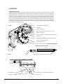
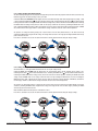
The Gassonic Observer consists of two chambers. In the ATEX certification the top chamber is an increased safety enclosure (EExe)
and the bottom chamber is a flameproof enclosure (EExd). In the UL/ULc certification the top chamber as well as the bottom chamber
are flameproof enclosures. The cables are connected through M20 x 1.5 cable entries in the top chamber using approved EExe glands
or approved conduit with seal installed within 18” of the detector. The inner cores of the cable penetrating the detector should be at
least 25 cm long. This will ensure no tension on the wires and connector PCB when the top chamber is opened. The two mounting bolts
are on the top chamber of the detector and this means that the cables will enter on the fixed part of the detector. The bottom part
is attached to the top by means of six allen screws with lock washers. Unscrewing these screws will expose the connector PCB in the
top chamber. These screws will be fixed by retaining washers to the bottom part. The bottom part of the detector is supported by the
Load-strap, which is connected to the top.
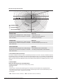
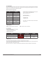
Figure 1.
1. Top (the fixed part of the detector)
2. Flame path
3. M5 Earth Connection
4. Inner top chamber (ATEX – EExe, UL/ULc – EExd)
5. M20 x 1.5 cable entry
6. Factory installed earth wire between top and bottom parts
7. Load-strap
8. Bulkhead separating the two chambers and permanently
attached to the bottom chamber.
9. EExe Connector PCB
10. Allen screw and lock washer (must be tightened with 9 Nm)
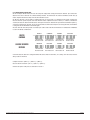
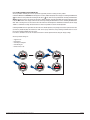
Wire lengths inside the top chamber
25 cm
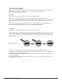
Figure 2.
Wire insulation stripped between 8 and 10 mm.
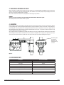
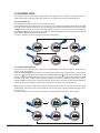
Optical link window
User Interface (Switches operated with magnet-stick)
Microphone
Test sound source
Installation and User Guide for Gassonic Observer (BB 6017-09)
Page 5