1
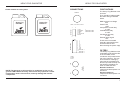
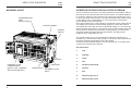
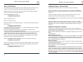
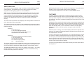
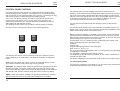
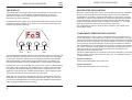
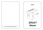
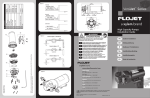
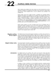
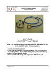
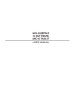
USER GUIDE
VERSION 1.0
Heavy Fog
Martin Professional A/S,Olof Palmes Allé 18, DK-8200,Aarhus N
Phone: +45 87 40 00 00 Internet: www.martin.dk
Glaciator
X-Stream
HEAVY FOG GLACIATOR
HEAVY FOG GLACIATOR
CONNECTIONS
Fluids Suitable for this system:
FUSE RATINGS
The Heavy Fog Glaciator uses
six fuses.
They should be replaced with
the value and type detailed
below:
REMOTE
Heavy Fog
Fluid B2
Heavy Fog
Fluid C3
1-GND, 2-12V OUT, 3-INPUT
6
1
INTERFACE
1 FOG
2 STANDBY
3 TIMER
4 FAN
5 LOW FLUID
6 GND
5
9
ON
DMX ADDRESS
1
2
3
4
5
6
7
8
9
10
11
12
1
2
4
8
16
32
64
128
256
SPECIAL 1
SPECIAL 2
SPECIAL 3
1 GND
2 COLD
3 HOT
OUT
DMX DATA
INPUT
IN
NOTE! The warranty on this machine is conditional on the use of
genuine JEM / Martin fluid only. Other fluids may represent a health
hazard when used in this machine, and may damage the internal
components.
7
8 REMOTE PUMP
9 REMOTE PUMP
DMX receiver low voltage
2AT
Power PCB
15AT
Compressor control relay
3.15AT
Local/Remote relay
3.15AT
Condenser fan relay
3.15AT
External pump signal
1AT
These fuses are located
internally and should not be
accessed without first
disconnecting the power supply.
FILTERS
The Heavy Fog Glaciator uses
a washable synthetic fibre filter
in the air intake for the
condenser unit (located at the
top of the machine). This can
be removed for cleaning by
removing the ventilation grill
above it (four M5 screws). Use
the following guidelines for
when to check the filter.
Normal Conditions:
Inspect and clean/replace every
250 hours
Severe Conditions:
Inspect and clean/replace every
150 hours
21
HEAVY FOG GLACIATOR
SPECIFICATION
HEAT EXCHANGER
3.5KW heater (@240V)
Wide bore steel vaporizing coil
Ceramic thermal trip for over-temperature protection
Electronic Temperature control using thermocouple
FLUID SYSTEM
Oscillating piston high pressure fluid pump
Low fluid detection by electronic sensor
5L fluid container (1.3 US Gal.)
Maximum fluid consumption 120mL/minute
REMOTE CONTROL OPTIONS
DMX512 decoder:
Required Channels = 2
Output is proportional for all levels above 12%
Channels supported = 1 to 511
Valid start codes = 0 (dimmer data only)
Full framing error detection implemented
Analogue control via standard JEM Multifunction Contoller.
PLC interface for simple switching control of the system.
CONTROL PANEL
2 x LED displays with 4 button keypad
Output level control from 0 to 100% for Fog
Timer range:
Delay time (toF) 0 seconds - 90 seconds
Run time (ton) 0 seconds - 90 seconds
REFRIGERATION UNIT
1 HP compressor with PWM electronic control
Uses refrigerant R404A (1.2 Kg)
OUTPUT CONNECTION
Ducting adaptor to accept 150mm (6”) flexible ducting
POWER REQUIREMENTS (dependant on model)
Input voltage 230V,50Hz single phase (32A supply)
Input power (max) 4.893KW @ 230V
Current (max) 22.2A
Input voltage 208V,60Hz single phase (32A supply)
Input power (max) 4.325KW @ 208V
Current (max) 21.9A
Power connection is via 32A 3 pin IEC appliance inlet (230V machines)
or fixed cable (208V machines).
20
HEAVY FOG GLACIATOR
USER
GUIDE
USER
GUIDE
USER GUIDE CONTENTS
Introduction
2
Features
2
Safety Guidelines
3
Machine Layout
4
Commissioning The Machine
5
Remote Control Options
5
DMX Operation
6
The Display
8
The Fluid System
10
Local Remote Fluid System
11
Refrigeration System Control
12
Evaporator Fan Control
13
Condenser Temperature Control
13
Control Panel Functions
14
The Timer
15
Basic Operation
16
Interface Options For Glaciator X-stream
17
Display Messages
18
Basic Fault Finding
19
Specification
20
Connections
21
Fuse Ratings
21
Filter Maintenance
21
© 2003 Martin Professional A/S, Denmark.
All rights reserved. No part of this manual may be reproduced, in any form or
by any means, without permission in writing from Martin Professional A/S,
Denmark.
1
HEAVY FOG GLACIATOR
HEAVY FOG GLACIATOR
USER
GUIDE
INTRODUCTION
USER
GUIDE
BASIC FAULT FINDING
The Heavy Fog Glaciator X-Stream is the latest product in the new
generation range of JEM professional machines. Designed for touring and
installation in a variety of applications, it has provision for easy integration
into most common control systems currently used in the entertainment
industry. As well as providing remote control options via DMX, the machine
comes with a comprehensive control panel for local operation and display of
operating parameters.
The Heavy Fog effect is provided by cooling the smoke output from the main
heat exchanger until it is at a temperature lower than the ambient in which
the machine is operating. Air is added to the smoke, prior to cooling, from
the fan mounted in the rear of the machine. This increases the volume of the
effect and allows the output to be pushed through ducting.
A fluid container with 5L capacity (1.3US Gal.) is provided for Heavy Fog
fluid. To allow reliable unattended operation, the fluid level is monitored
electronically, and the machine shut down if necessary.
All machines come with robust carrying handles, and heavy duty braked
castors. A ducting adaptor as an accessory.
FEATURES
Tubeless condenser
Electronic low fluid detection
5L fluid capacity/Remote fluid
High pressure piston pump.
Pump Ramping system for
continuous operation
LED displays for FOG and ICE
controls.
Electronic expansion valve
Fog and Density controls for easy
set-up.
The Heavy Fog Glaciator is a complex machine and will require a competent
service technician to repair any major faults. However, the following guide
will allow the user to overcome the more common problems.
SYMPTOM
CAUSE
CURE
No fog output when the Machine is not ready
machine is fired using
Fluid is below min level
the Fog or Timer switch. Standby switch is OFF
Allow time to reheat
Add fluid
Set standby to ON
No fog output when
using DMX to fire the
machine.
Incorrect DMX address
Machine not ready
No DMX termination
Check settings
Allow time with DMX on
Fit 120 ohm resistor
Flu Lo is displayed on
the Fog display
Fluid level is below min Add more fluid
Machine is not ready
after 20 minutes
heating time
Standby switch is OFF
Blown fuse on Power
control PCB
Fog disperses too
quickly
Wrong grade of fluid
Choose a longer lasting
used for the application fluid (see front cover)
Density level too low
Increase density setting
(Reduces fan speed)
Set Standby ON
Disconnect supply and
replace fuse.
3.5KW heat exchanger
Accurate timer
DMX512 interface (two channel)
Remote interface.
Integrated PLC interface
Non-volatile memory for user
settings
2
Two speed condenser fans
for reduced noise
19
HEAVY FOG GLACIATOR
HEAVY FOG GLACIATOR
USER
GUIDE
USER
GUIDE
DISPLAY MESSAGES
SAFETY GUIDELINES
The following list shows the messages possible, and the context under which
they are displayed. Only the messages available under normal operation are
shown. Messages shown when using the menus, are detailed in other
sections of this handbook.
Always use JEM/Martin approved fluid in the container supplied with the
machine. Do not bypass the fluid sensor, this could cause damage to the
machine.
Fog Display
Fog/oFF
Displayed when the Standby switch is set to OFF, indicating
that the machine can not be fired and the heaters are OFF.
Fog/Err
Shows that the Standby switch is ON but the heater is not
on. This is an error condition and should not normally occur.
Check the voltage is correct for use with the machine, the voltage setting is
printed on the serial label.
The machine must be operated in a horizontal position and should not be
suspended overhead.
Observe the warnings displayed on the machine (yellow labels).
Fog/Ht
Displayed when the heater is running but the machine is not
ready.
Do not remove the covers or attempt to repair a faulty machine, an authorized JEM dealer should be contacted in the event of a faulty machine.
Fog/rdy
The machine is ready to fire using the Fog or Timer
switches.
Always use smoke machines in well ventilated areas, over-use could affect
sufferers of asthma or other chest conditions.
FLu/Lo
Indicates that the fluid in the container is below the minimum
level to operate the machine. Only visible when the machine
has reached the ready state.
Smoke machines can cause condensation to form. Floors and surfaces may
become slippery and should be checked regularly.
Fog/08
The FOG switch is being used to fire the machine. The
number displayed is the current Fog output level in the
range 0 to 20
This machine is not waterproof, and should not be exposed to wet outdoor
conditions. Do not spill fluid over the machine. If fluid is spilt, clean with a
damp cloth and contact an approved JEM dealer for advice.
Refer servicing to qualified service personnel. Disconnect the machine from
the power supply before removing any covers.
Mains Cable Wiring Instructions
Ice Display
dEn/oFF
Displayed when the Standby switch is set to OFF.
dEn/nor
Shows the current Density setting.
This equipment
must be earthed.
Brown = Live
Blue = Neutral
Green / Yellow = Earth
18
The Heavy Fog Glaciator is fitted with
an IEC 32A single phase connector. A
suitable 32A,230V supply must be
used.
On the 208V/60Hz version of the
machine, the IEC connector is
replaced by a fixed cable.
To connect to US 208V supplies, the
neutral conductor can be connected
to the second phase of the 120V
system, while phase 1 is connected to
the Live conductor.
3
HEAVY FOG GLACIATOR
HEAVY FOG GLACIATOR
USER
GUIDE
MACHINE LAYOUT
USER
GUIDE
INTERFACE OPTIONS FOR GLACIATOR X-STREAM
CONDENSER AIR
INLET
(WITH FILTER)
CONTROL PANEL
POWER
SWITCH
The PLC interface connector is now fully operational on all models, without
the need to fit an extra interface PCB to the machine. This allows installers
to control the functions of the machine using active low signals from a PLC
or other automatic control system. The fog and density levels must be preset
on the display units, or alternatively, a 0-10v signal can be used at the
remote interface connector (XLR3).
Since the interface has no opto-isolators, the external control system should
use voltage free contacts or opto-isolated outputs to control the machine.
The signals are active low, and need a threshold voltage of 1.5V or less @
2mA to activate the functions. The internal circuits of the interface offer very
little overload or interference protection, meaning that any control device
should be located physically close to the machine. This will prevent
problems due to long cable runs etc.
The special function pin 5, is now allocated to allow the machine to be
shutdown by a remote fluid sensing system. The input is active low and has
the same electrical specification as the other inputs.
To allow the external fluid system to use a remote pump, a ‘normally open’
contact is connected to pins 8 and 9.
Pin Allocations:
1
Fog
2
Standby
3
Timer
4
Fan
5
Shutdown (low fluid)
6
Ground
7
N/C
8
Remote pump run A
9
Remote pump run B
AIR INLET
INTERNAL FLUID
COMPARTMENT
(WITH LOCAL / REMOTE
SELECTION SWITCH)
4
DRIP TRAY
POWER INLET
EXTERNAL FLUID
INLET
17
HEAVY FOG GLACIATOR
USER
GUIDE
HEAVY FOG GLACIATOR
USER
GUIDE
BASIC OPERATION
COMMISSIONING THE MACHINE
The following instructions explain how to operate the basic functions of the
machine. It is assumed that the machine is being started from cold.
Unpack the machine and look for any obvious signs of damage.
Starting with all the control panel switches OFF, and the display showing
‘OFF’, go through the following sequence.
Place the machine on a level surface and fit a container of JEM/Martin
approved fluid into the fluid compartment. Fit the fluid line and cap to the
container.
Set the Standby switch to ON.
Fog display shows FOG/Ht
Ice display shows Den/nor
Check the wiring instructions in the Safety Guidelines section of this
handbook and connect the machine to the power supply.
Set the output to Fog = 8
Set the power switch to the ON position, and look for the start-up message
on the displays.
Set the Ice switch to ON
When the machine is ready (after approx. 10 minutes heat-up time) fog can
be produced.
Fog display shows FOG/Rdy
Ice display shows Den/nor
If starting the machine for the first time, or after the fluid has been changed,
the pump may need to be primed.
Do this by setting the Fog output to 20 and firing the machine for 10
seconds, or until fog is produced at the output.
If the pumps have not primed after 40 seconds, there may be a problem with
the fluid system. Refer to the Fault Finding section of the handbook for
advice. The unit may not prime properly if the ice system is not at -15 or
below. This can be overcome by switching the ICE switch to off, and then
priming the pump as previously described.
Set the Fog switch to ON to produce continuous output of Heavy Fog.
Fog display shows FOG/08
Ice display shows Den/nor
Set the Timer switch to ON to produce timed output (read the Timer section
to see how to configure the timer). Note that the Fog switch overrides the
timer switch.
Fog display shows ton/04,toff/03 etc
Ice display shows Den/nor
16
Set all the switches on the control panel to OFF and refer to the Basic
Operation section of this handbook for information on how to use the main
functions of the machine. Read the Safety Guidelines before using the
machine.
REMOTE CONTROL OPTIONS
The Heavy Fog Glaciator provides the user with 3 ways to implement a
remote control on the machine. The main control panel is fixed and can not
be removed for remote operation.
All the remote interfaces are located on the panel adjacent to the control
panel.
The options are:
DMX 512 Digital Interface.
The interface uses the two XLR 3 connectors marked DMX on the interface
panel, and uses the usual DMX electrical standards (RS 485). The inputs
are protected against overvoltage and an ouput connector is provided to
allow multidrop operation of the link.
Remote Interface.
The remote interface uses an XLR 3 connector to allow a standard JEM
remote to fire the machine.
Full proportional control of the Fog output can be achieved, but the Density
level must be set on the control panel.
PLC Interface.
This connection is an option available to installers who wish to control the
machine using the ouputs from a standard Programable Logic Controller
(PLC). The interface allows ‘voltage free’ control signals to switch the Fog,
Standby, Timer and Ice functions. The output levels and timer settings must
be made using the control panel. See the section called Interface Options
for more information.
5
HEAVY FOG GLACIATOR
HEAVY FOG GLACIATOR
USER
GUIDE
USER
GUIDE
DMX OPERATION
The machine may be operated using the industry standard DMX 512 digital
control protocol. This allows the control of the fog system to be easily
integrated with the lighting system in most installations.
DMX may be used without changing any of the settings on the main control
panel. When the system detects a valid DMX data stream on the input, the
control will default to the DMX system levels. Any attempts to control the
machine from the control panel will have no effect until the DMX signal is
removed. The displays will show the current input values for Fog and
Density.
To ensure correct operation of the displays, the standby switch should be set
to the ON position when using DMX.
The machine requires two channels, with the address of the first channel set
on the DIP switch. The channels control the FOG and Density settings in the
following manner.
Channel 1
FOG output level
0 - 32 zero output (dead-band)
33 - 255 proportional output level control
Implemented in 20 discrete steps
Channel 2
Compressor switching and Density setting
0 - 32 Compressor off
33 - 65 Low (Lo) density
66 - 98 Normal (Nor) density
99 High (Hi) density
The system implements true proportional control of the fog output rather than
the simple switching functions found on other equipment. The output levels
of FOG and FAN are linked during DMX operation via the Density setting.
ICE: Setting this switch to ON, will start the compressor. There will always be
a delay of up to 20 seconds to allow pressure equalisation.
This function is independent of the status of the STANDBY switch.
THE TIMER
The timer system is implemented in software using the machine’s main
control PCB. As such, the timing is crystal controlled and will be of good
accuracy when compared to the usual analogue timers commonly found on
fog machines. The timer is enabled by setting the Timer switch on the control
panel to ON.
Pressing the Timer switch will cause the timer to start from the beginning of
the ON period and run through to the end of the OFF period, the cycle will
then repeat until the Timer switch is set to OFF. The timer will only function
when the Standby switch is set to ON and the machine is ready (RdY).
Switching the Timer to OFF at any time during the cycle will halt the
operation.
While the timer is running, the left-hand display will show the elapsed time in
seconds. The display will alternate between the period name (ton/toF) and
the elapsed time in seconds.
To set the time periods, use the Menu key on the left-hand display to set the
‘ton’ menu as current. Press the Enter key to see the current value for the
On Time (ton), and make adjustments using the Up/Down keys. Now press
enter to store the value and use the menu key to select the Off Time (toF)
menu. Adjust the value as for the On Time, and then enable the Timer switch
on the control panel to test the settings.
The current Fog and Density levels will be used by the timer system when in
the ON period.
The DMX base address can be set to any channel in the range 1 - 511 using
the DIP switches. The channel number must first be decoded into binary
format before being set into the switches.
6
15
HEAVY FOG GLACIATOR
USER
GUIDE
HEAVY FOG GLACIATOR
USER
GUIDE
CONTROL PANEL FUNTIONS
The control panel provides a means to enable the various functions that
control the Fog and Ice operation. The switches have a maintained action,
and are used to set the operating mode of the machine. The settings for Fog
and Density levels are made using the LED display keypad.
The Lo,Nor & Hi density settings are used to relate the fan speed to the
current level of fog output. Use Lo density when using ducting to get
maximum thrust from the fan , and use Hi density to create a very dense
effect (although with reduced volume).
The ramping control system may overide the density setting if required.
The machine uses a ‘pump ramping’ technique to allow continuous
operation. This means that transmitting DMX 100% will cause the machine to
run at full output until the temperature falls and the output is automatically
reduced. The output will remain at this level until the DMX signal is reduced,
or the fluid is exhausted. There is no possibility of damage, since the
electronic fluid level sensor will shut the machine down.
The layout of the control panel is shown in the following drawing.
The onboard timer functions are not accessable via the DMX system. Any
timing of the output must be done using the programming capabilities of the
DMX console being used to control the system.
0
0
1
1
TIMER
ICE
0
0
1
1
FOG
STANDBY
The switches are used to set the operating mode of the machine and are
used individually or in combination. The functions available are explained
below.
FOG: Gives Fog output at the level currently set using the display system.
The machine must be Ready before fog can be produced.
STANDBY: The standby switch brings the machine into operating mode and
will start the heater. This switch must be ON to use the Fog switch or the
Timer. When Standby is OFF, the machine will display OFF on both displays.
With standby ON, and the machine ready, Rdy will be on the Fog display.
The fan output level is affected by the ramping system via the Density
setting.
Setting of the base address of the DMX control system via the Dip-switch,
requires the decimal address to be converted to a binary (base 2) number.
Many pocket calculators can perform this conversion, or the user can read
off the settings from a printed conversion table.
An alternative is to use a simple process of subtracting the largest of the
binary weightings that leave a positive result.
Example:
Decimal 289.
Largest subtraction possible is 256, leaving 33.
Now, 33-32 = 1, and 1-1 =0.
So, we need a binary representation with 1’s in the positions corresponding
to weightings of 1,32,256.
Or, 100100001, where 256 is the leading column.
The weighting on the Dip-switch is reversed, so the number 100001001 is
entered from left to right.
The binary weightings on the Dip-switch read as folows ( from left to right):
1,2,4,8,16,32,64,128,256
The remaining 3 switches are marked S1,2,3, and are function switches that
enable special operating modes on the machine.
TIMER : When the machine is Ready, (at operating temperature), the timer
switch will start the timer running using the settings from the display.
14
7
HEAVY FOG GLACIATOR
USER
GUIDE
HEAVY FOG GLACIATOR
USER
GUIDE
THE DISPLAY
EVAPORATOR FAN CONTROL
Two LED displays are used in the Heavy Fog Glaciator to show status and
control information. The left display shows all information for the fog
generation functions of the machine, whilst the right display shows the
information for the Ice functions.
When the current firing cycle is over, the evaporator fan will run at maximum
speed for 3 seconds to clear the remaining smoke from the evaporator
compartment. To allow for machines with ducting on the output, a special
extended run mode can be selected. By setting the special function switch 1
(s1) to ON (down), a 6 second run-on time for the evaporator fan can be
selected. Remember that the density setting for ducting is ‘Lo’, since this
gives the greatest fan speed for any given fog output level.
The evaporator fan may run at other times to assist in the control of the
refrigeration system.
Located below each display are 4 function keys that can be used to control
the display and the settings on the machine. The functions of the keys are
shown in the following drawing.
CONDENSER TEMPERATURE CONTROL
MENU
KEY
ENTER UP KEY
KEY
DOWN
KEY
The message displayed will depend on the operating mode of the machine at
the time. However, pressing the menu key at any time will cause the display
to go into the edit mode, allowing the operating parameters to be adjusted.
After approximately 15 seconds since the last keystroke, the display will
leave the edit mode and revert to displaying the current status information.
Pressing the menu key will display the current menu function, whilst pressing
and holding will scroll through the available menus. All keys work the same
way, and can be operated with single keystrokes or held down to force the
display to scroll through the available options/values. The scrolling function
comes into operation 1 second after the key is pressed.
The radial blowers used to cool the condenser unit are powered from a 2
speed relay which is controlled by the machine’s microprocessor. The speed
of the fans is determined by the temperature of the condenser unit and the
thermal load on the evaporator. The control software uses a timer to prevent
short-cycling of the speed controller. Under almost all ambient conditions,
the fans should run at low speed when the machine is idling, but when fired,
the system will switch to high speed. The high speed running will continue
after the end of the current firing cycle, and is timed according to the
temperature of the condenser unit.
The filter material fitted to the condenser unit can be changed by removing
the four screws securing the condenser top cover. The guidelines for filter
change/cleaning are:
Normal conditions:
Inspect and clean/replace every 250 hours.
Severe conditions:
Inspect and clean/replace every 150 hours.
When the user has set the required menu function, pressing the enter key
will display the current value associated with that menu item. The user can
now use the UP/DOWN keys to move through the available options/values
either by single keystrokes or by scrolling.
8
13
HEAVY FOG GLACIATOR
USER
GUIDE
HEAVY FOG GLACIATOR
USER
GUIDE
REFRIGERATION SYSTEM CONTROL
The performance of the refrigeration system in the Heavy Fog Glaciator is
the key to its heavy fog generating capability. The system is under the
complete control of the main microprocessor which also co-ordinates all the
other activities within the machine.
Four system temperatures are measured by the control system and are used
to regulate the flow of refrigerant via the PWM expansion valve. Replacing
the normal thermo-mechanical expansion valve with an electronically
controlled valve brings the following benefits:
Faster response to load changes
Improved control when on light loads
No adjustments required
Greater tolerance to changes in gas charge
Improved compressor starting when hot
Power saving idle mode
When the refrigeration system is switched off using the ICE switch on the
control panel it can only be started by setting the switch to ON. There will be
a delay of 10 to 30 seconds while the system pressures equalise, followed
by the motor starting. During the motor start cycle, the heaters are switched
off to reduce the peak current draw.
If the ICE switch is ON, but the compressor is not running, the system is in
power save mode. It will restart when the smoke system is fired (any signal
source) or when the ice switch is cycled. The starting delay will depend on
the current evaporator temperature, but will not prevent immediate
production of fog at full output.
If the machine is not fired, the evaporator temperature will drop to -25°C or
lower and a timer will start. When the unit has been at this temperature
(without being fired) for approximately 20 minutes, the system will shut down
and enter the power saving mode. Power save mode will continue until the
machine is fired, or the evaporator temperature reaches -4°C.
To check the status of the refrigeration system at any time, use the ICE
menu on the right hand display panel. The left hand panel will now display
the name of the value, while the right hand display will show the
temperature. Use the scroll keys on the right hand display to move through
the available values.
12
To store the new value into non-volatile memory, the enter key must be
pressed before moving on to another menu or leaving the edit mode.
When not in edit mode, the display will show information appropriate to the
current operating mode. To do this, the display will alternate between two
messages. The duration of the first message is typically 1 second, whilst the
second message will be visible for 2 seconds. Some messages are
compounded together to form one message, eg FLu/Lo indicating low fluid in
the fluid container.
As an example, when the STANDBY switch on the control panel is set to
OFF (0), the display will alternate between FOG and OFF. For more
information about the messages to expect, see the sections covering the
different control functions on the machine, eg ‘THE TIMER’. The section
entitled ‘DISPLAY MESSAGES’ contains a complete list of the messages
and the circumstances under which they are displayed.
The menus available on each display and the functions they perform are as
follows:
Fog Display
Fog
Sets the current Fog output level in the range 0 to 20.
Ton
Sets the ON time of the Timer in the range 0 to 90 (seconds).
ToF
Sets the OFF time of the Timer in the range 0 to 90 (seconds).
Ice Display
Den
Sets the output density level (Lo,Nor,Hi).
SuP
Sets the supply voltage in the range 200 to 250v.
Ice
Displays current system temperatures.
The software that controls the displays and the other functions of the
machine is stored in ‘Flash’ memory on the DMX receiver PCB. As new
features become available, this program code can be updated by using the
Martin Uploader programming device for the AVR microprocessor.
9
HEAVY FOG GLACIATOR
USER
GUIDE
HEAVY FOG GLACIATOR
USER
GUIDE
THE FLUID SYSTEM
LOCAL/REMOTE FLUID SYSTEM
The Heavy Fog Glaciator uses a 5L (1.3 US Gal.) container to give
approximately 1.5 hours of continuous operation at full output. This will vary
with power supply voltage, which will determine the maximum continuous
output level. For longer run times, the remote fluid system can be used.
The Local / Remote fluid system used on the Glaciator gives users the
flexibility of using either the built-in 5L container (with sensor), or a remote
supply. The remote supply can be up to 100m away from the machine if a
suitable slave pump is used at the reservoir.
An output, which is active when the machine is firing, is provided on the 9way D-type connector (pins 8 & 9). This signal can be combined with the
signal from a pressure switch, to control the remote pump which must have
a maximum output pressure of 3 bar.
These contacts are voltage free, and allow the remote pump to be active
only when the machine is fired. Since the contacts are voltage free, they can
be connected in parallel with the signals from other Glaciators which share
the same fluid supply. This forms a ‘wired or’ function, which enables the
pump when any/ all machines are operated. The output must not be used to
control mains (line/net) voltages directly.
To select between local or remote fluid, open the door of the fluid
compartment and operate the toggle switch mounted in the top of the
compartment side panel. The local fluid sensor will be disabled when in
remote mode, but the remote system can shut the machine down by using
pin 5 of the interface connector (9-way D-type). This allows a remote system
to be constructed which includes a fluid sensor, thus preventing the system
from running dry.
The input on pin 5 must be pulled low, relative to the ground on pin 6.
Ground isolation should be provided between the two systems, by using
relays or opto-isolators.
The remote fluid connection is a 6mm ‘push fit’ style pneumatic fitting, and
should be used with nylon or PTFE tubing having a 10 bar pressure rating.
The machine control system uses a ‘Pump Ramping’ technique to allow
continuous operation with moderate input power requirements. When the
output level is set to maximum, the machine will give maximum output until
the heat exchanger has used its energy reserves. The control system will
then override the output level setting and reduce the pump speed to match
the output to the available input power. This ensures that the output will be
continuous, although at a reduced level.
Continuous operation gives rise to the possibility of pump damage if the
machine runs out of fluid. This is overcome in the Heavy Fog Glaciator by
using an electronic fluid sensing system, ensuring that the pump is shut
down when the fluid level is too low. The Left-hand display will show a Lo Flu
message to warn the user that the machine is shut down due to lack of fluid.
Variations in pump performance due to supply frequency differences
(50/60Hz), are compensated for automatically. Supply voltage changes will
also affect the pump performance, and can be catered for by using the
Supply Voltage menu (SuP) on the right-hand display unit. Using the Menu
key, select the SuP menu and press enter. Now adjust the voltage to match
the local power supply voltage (valid range is 200 - 250V). Press the enter
key to store the new setting in non-volatile memory. The pumps will now run
at the optimum level for the conditions.
Remember that the type of fluid used will play a large part in determining the
resulting effect. The list of fluids inside the front cover of this handbook
shows the main fluids compatible with this machine. Choose a fluid suitable
for the venue and type of effect you want to create. Generally, use the
standard B2 fluid, but for longer lasting effects, contact a distributor for
advice on using another fluid grade.
When operating the machine for long periods, there will always be a build-up
of condensation in the evaporator unit. This will drain into the drip tray, which
should be emptied regularly. For installation, an optional drain hose can be
fitted.
When using a remote slave pump, the suction line must be fitted with a
suitable filter such as Martin part number 26480020.
The most suitable type of pump, is a diaphragm unit similar to ‘FloJet’ style
2100, which includes a pressure switch. To prevent the liquid being forced
through the internal pumps, the maximum pressure in the feed line to the
machine should be 3 bar (44psi).
For distances to the reservoir of less than 6m, a slave pump is not required.
To prime the pumping system, the ‘Ice’ switch should be set to OFF, to allow
the machine to run the pumps at maximum output. Alternatively, wait until
the refrigeration system cools to below -10, at which point the pump ramping
system will become inactive, and maximum output will be available.
Note: All pressures are quoted as gauge pressure.
10
11