1
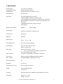
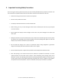
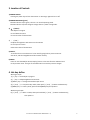
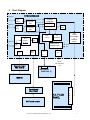
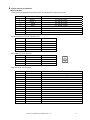
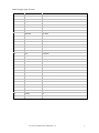
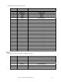
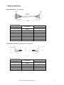
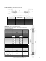
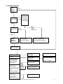
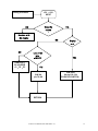
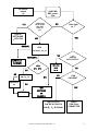
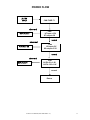
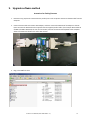
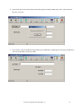
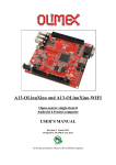
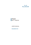
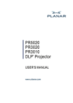
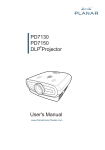
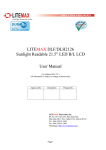
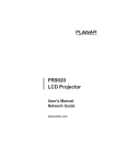
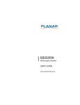
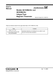
LT1201
USER MANUAL
www.planar.com
TABLE OF CONTENTS 1. Specification 2. Important Servicing Safety Precaution 3. Location of Controls 4. Hot‐key define 5. Block Diagram 6 Internal connector pin definition 7. Cable pin definition 8. Trouble Shooting 9. Upgrade software method LT1201 User Manual (020-1080-00 Rev. A)
3 4 5 5 6 7 10 12 16 2
1. Specification LCD panel type Displayable resolution Pixel dimension LCD display color OSD control Manual control buttons Viewing angle Contrast ratio Brightness Response time Active display area AC/DC adapter Input signal Input connector Touch screen MSR (option) Power management Regulation Dimensions ( W x D x H ) Weight Accessory Temperature 12.1” TFT (12.1” Diagonal) WXGA 1280 x 800 maximum 0.204 mm horizontal x 0.204 mm vertical
262,144 Colors Exit, Positioning(Horizontal, Vertical) Image Settings(Auto Adjust, Pixel Clock, Phase) Color Setting(Auto Color, 9300K Preset, 6500K Preset, User Preset) OSD Setting(Horizontal Position, Vertical Position, OSD Hold Time, OSD Lock), Language(English, Español, Français, Deutsch) Factory Reset POWER , + , - ,SELECT , MENU Horizontal: ± 89, Vertical: ± 89. (CR>10) 500:1 (Typ.) 300 cd/m2 30 ms, Tr+Td (Typ.) 261.12 mm (H) x163.20mm (V)
Input: AC 100 ~ 240V, 50 ~ 60 Hz Output: +12 Vdc / 3.0A Video: Analog 0.7 Vp‐p. 75 ohms Sync. : TTL Level, Positive/ Negative, Separate Sync. DVI : REV1.0 Digital Single T.M.D.S. 15 Pin D‐Sub. , 24Pin DVI‐D , USB B‐type , 2.5ψ DC‐Jack 3M Cap. (SCT3250 98‐0003‐3205‐0 & EXII‐7730HC) ID‐TECH (CPR60029 , USB Interface, 3 Track) Yes cUL, FCC, CE 341 mm x 280 mm x 95 mm. 220 g. (LCD Module only) 2.1 Kg. (unit) VGA cable, DVI‐D cable, USB cable, AC/DC adapter, power cord. Operation : 0 ~ 40°C Storage : ‐20 ~ 60°C LT1201 User Manual (020-1080-00 Rev. A)
3
LT1201 User Manual (020-1080-00 Rev. A)
4
2. Important Servicing Safety Precautions Prior to using this manual, please ensure that you have carefully followed all the procedures outlined in the user manual for this product. Read all of these instructions. Save these instructions for later use. • Follow all warnings and instructions marked on the product. •
Do not use this product near water. •
This display should be installed on a solid horizontal base. •
When cleaning, use only a neutral detergent cleaner with a soft damp cloth. Do not spray with liquid or aerosol cleaners. •
Do not expose this display to direct sunlight or heat. Hot air may cause damage to the cabinet and other parts. •
Adequate ventilation must be maintained to ensure reliable and continued operation and to protect the display from overheating. Do not block ventilation slots and openings with objects or install the display in a place where ventilation may be hindered. •
Do not install this display near a motor or transformer where strong magnetism is generated. Images on the display will become distorted and the color irregular. •
Do not allow metal pieces or objects of any kind fall into the display from ventilation holes. •
Slots and openings in the cabinet and the back or bottom are provided for ventilation, to ensure reliable operation of the product and to protect it from overheating, those openings muse not be blocked or covered. The openings should never be blocked by placing the product on a bed, sofa, rug, or other similar surface. This product should never be placed near or over a radiator or heat register. This product should not be placed in a built‐in installation unless proper ventilation is provided. LT1201 User Manual (020-1080-00 Rev. A)
5
3. Location of Controls 1) POWER SWITCH Pressing the power key will turn the monitor on. Pressing it again will turn it off. 2) POWER INDICATOR (green) The LED indicator lamp is green; the unit is in normal operating mode. The LED indicator lamp will change to orange when it is power‐saving mode. 3) + : ( RIGHT ) Auto Adjust in Progress to scroll down the menu to increase value of selected item 4) - : ( LEFT ) to adjust the brightness and contrast on the monitor to scroll up in the menu to decrease value of selected item 5) SELECT: To confirm the current selection. It’s also used for going back to previous menu or sub‐menu, and the changed data will be saved to memory. 6) MENU: Enters or exits the OSD (On Screen Display) menus. It also exits from the submenu back to the previous menu. This type of cancellation will not save the previous changes. 4. Hot‐key define With signal input : 1) [+] key ==> Auto adjust in progress 2) [-] key ==> Adjust Brightness and Contrast 3) [SELECT] key ==> change VGA and DVI input source 4) [+] and [-] ==> key lock & key unlock, when push [+] and [-] buttons simultaneously 5) [MENU] key ==> Factory mode, push and hold [MENU] key then power‐in Without signal input: 6) [+] and [-] ==> Burn‐in mode, when push and hold [+] and [-] buttons simultaneously, Then power‐in LT1201 User Manual (020-1080-00 Rev. A)
6
5. Block Diagram INTERFACE BOARD
COMPUTE
R
CN2
(DB15)
CN3
DDC
UH1
HUB 2.0
COMPUTE
X1
OSC
U3 (24C02)
(DVI)
R
SCALER
DDC
COMPUTE
R
U4 MStar
TSUM5PNJ
U1(24C02)
XH1
OSC
Flash
U6
memory
EEPROM
GL850G
SWITCH MODE
PH1
POWER SUPPLY
B-type
PH3
PH2
5PIN
5PIN
J1
8
CN5
30 PIN
LVDS CABLE
&
Backlight
control
3.3V
5V
JP1
FROM
A/D ADAPTOR
Connector board
PWB-5818 (2)
JP1
12V
SW BOARD
PWB-5818 (1)
MSR kit
C
Control board
EXII-7730HC
O
12.1” LCD
PANEL
3M Touch screen
LT1201 User Manual (020-1080-00 Rev. A)
N
N
E
C
T
7
6. Internal connector pin definition WXGA I/F BOARD J1: Key Switch for OSD Adjustment, Power Switch and Brightness Control Input Terminal Pin No. Symbol Function 1 2 3 4 5 6 7 8 ADJUST / ‐
ADJUST / + MENU SELECT POWER LED‐GRN LED‐ORG GND PH2.PH3: Output Terminal for USB device unit Pin No. Cable Color
1 2 3 4 5 Red White Green Black Drain wire PH1: USB B‐type Input Terminals Pin No. Cable Color 1 2 3 4 Red White Green Black For OSD Adjustment For OSD Adjustment For OSD Adjustment For OSD Adjustment For POWER on/off Normal Mode: Low Save Mode : Low Ground Function
VBUS(5 Volts) D‐ D+
Ground Shield ground Function VBUS(5 Volts)
D‐ D+ Ground CN2: VGA Signal Input Terminals Pin No. Symbol 1 2 3 4 5 6 7 8 9 10 11 12 13 14 15 VGA R VGA G VGA B NC GND RED RETURN GREEN RETURN BLUE RETURN
5V DCC VGA CONN NC VGA SDA VGA HS VGA VS VGA SCL Function RED Video Input Signal GREEN Video Input Signal BLUE Video Input Signal GND
GND for RED video signal GND for GREEN video signal GND for BLUE video signal Support DDC +5V power Detect VGA connector signal DDC data Horizontal Sync. Signal Vertical Sync. Signal DDC clock LT1201 User Manual (020-1080-00 Rev. A)
8
CON3: DVI Signal Input Terminals Pin NO. Symbol Function 1 Dat2‐ T.M.D.S Data2‐ 2 Dat2+ T.M.D.S Data2+ 3 2/4 Shield T.M.D.S Data2/4 Shield
4 Dat4‐ T.M.D.S Data4‐ 5 Dat4+ T.M.D.S Data4+ 6 DDC SCL DDC Clock 7 DDC SDA DDC Data
8 VSYNC NC 9 Dat1‐ T.M.D.S Data1‐ 10 Dat1+ T.M.D.S Data1+ 11 1/3 Shield T.M.D.S Data1/3 Shield
12 Dat3‐ T.M.D.S Data3‐ 13 Dat3+ T.M.D.S Data3+ 14 +5V +5V Power 15 SYNC GND Ground
16 HPD Hot Plug Detect 17 Dat0‐ T.M.D.S Data0‐ 18 Dat0+ T.M.D.S Data0+ 19 0/5 Shield T.M.D.S Data0/5 Shield
20 Dat5‐ T.M.D.S Data5‐ 21 Dat5+ T.M.D.S Data5+ 22 CLK Shield T.M.D.S Clock Shield 23 CLK+ T.M.D.S Clock+ 24 CLK‐ T.M.D.S Clock‐ C1 Red NC C2 Green NC C3 Blue NC
C4 HSYNC NC C5 RGB GND NC LT1201 User Manual (020-1080-00 Rev. A)
9
CN5: Output Terminal for Panel Connector Pin No. Symbol 1 PANEL_VCC 2 PANEL_VCC 3 PANEL_VCC
4 LVDS_SET 5 GND 6 GND 7 RXE0‐ 8 VDD_EDID 9 RXE0+ 10 GND 11 RXE1‐ 12 CLK_EDID 13 RXE1+ 14 DATA_EDID 15 RXE2‐ 16 GND 17 RXE2+ 18 VDIM 19 RXEC‐ 20 BL ON 21 RXC+ 22 GND 23 RXE3‐ 24 Black‐light VCC 12V
25 26 27 28 29 30 RXE3+ Black‐light VCC 12V GND Black‐light VCC 12V GND Black‐light VCC 12V SW board JP1: Output Terminal for OSD, Power and Brightness control. Symbol 1 POWER 2 LED‐GRN 3 LED‐ORG 4 ADJUST / +
5 ADJUST / ‐ 6 SELECT 7 MENU 8 GND LT1201 User Manual (020-1080-00 Rev. A)
Function 3.3 Power supply 3.3 Power supply 3.3 Power supply LVDS_SET Ground Ground Receiver signal (‐) VCC 3.3V Receiver signal (+) Ground Receiver signal (‐) CLK_EDID Receiver signal (+) DATA_EDID Receiver signal (‐) Ground Receiver signal (+) Adjust back‐light Clock signal (‐) Black‐light on/off Clock signal (+) Ground Receiver signal (‐) VCC 12V for back‐light device Receiver signal (+) VCC 12V for back‐light device Ground VCC 12V for back‐light device Ground VCC 12V for back‐light device Function For POWER on/off Normal Mode: Low Save Mode: Low For OSD Adjustment For OSD Adjustment For OSD Adjustment For OSD Adjustment Ground 10
7. Cable pin definition Switch board cable: WIRE 28AWG Connection relationship P1 (PHR‐8) WIRE COLOR Pin No. 1 2 3 4 5 6 7 8 BLACK BROWN RED ORANGE YELLOW GREEN BLUE PURPLE P2 (ZHR‐8) Pin No.
5 4 7 6 1 3 2 8 Int. C/B cable for 3M touch: WIRE 28AWG, Shielding cable Connection relationship P1 (PHR‐5) WIRE COLOR Pin No. 1 2 3 4 5 BLACK
BROWN RED ORANGE DRAIN
LT1201 User Manual (020-1080-00 Rev. A)
P2 (ZHR‐5) Pin No. 1
2 3 4 5
11
Int. MSR extend cable: WIRE 28AWG, Shielding cable
Connection relationship
P1 (PHR-5)
Pin No.
P2
WIRE COLOR
1
2
3
4
5
BLACK
BROWN
RED
ORANGE
DRAIN
(PHR-5)
Pin No.
1
2
3
4
5
LVDS cable: WIRE UL10064 34# OD: 0.35mm
CN1 housing: JAE FI-JT40C-R3000
CNC housing: ACS 87219-3000
Connection relationship
CN1
1
3
4
5
6
8
9
13
14
16
17
19
20
22
23
25
26
29
34
35
36
37
40
twist
twist
twist
twist
twist
WIRE COLOR
BLACK
BROWN
RED
ORANGE
YELLOW
BLACK
WHITE
BROWN
WHITE
RED
WHITE
ORANGE
WHITE
YELLOW
WHITE
GREEN
BLUE
PURPLE
GRAY
WHITE
BLACK
BROWN
RED
10、11、15
18、21、24
twist
twist
twist
twist
twist
CN2
5
1
2
3
8
12
14
7
9
11
13
15
17
19
21
18
20
22
24
26
28
30
6
10、16
GND
27、29
NC
4、23、25
28、30、31、32
2、7、12
LT1201 User Manual (020-1080-00 Rev. A)
12
27、33、38、39
LT1201 User Manual (020-1080-00 Rev. A)
13
8. Trouble Shooting Does
picture
display?
YES
NO
On
Back-light
On or off?
A dark
picture or a
picture full
of colorfully
vertical lines
Off
Check
power LED
Hsync,
Vsync
or DE error
Green
Flash
Check
display
resolution
Check inverter
Check I/F board J5
Check I/F board CN5
Check panel connector
Check I/F board
OSD no response
too dim
The brightness is
different between
upper side and
downer side.
Check SW board
SW1~SW4
Check I/F board
Check OSD
adjustment
Check SW board JP1
Check I/F board
partly picture
without color
Vertical, Horizontal
none
synchronousness
a few of colorfully
vertical lines
RGB
signal
error
H,Vsyn
c error
Check backlight
Check I/F board
Check LCD panel
Check LCD Panel
even(or odd)
vertical lines is dark
LT1201 User Manual (020-1080-00 Rev. A)
14
JP1 , +12V
INPUT
Debug Procedure
Does the
NO
YES
screen
l
Solution with
No display
NO
Display
ok ?
NO
Lost some
bits
of RGB??
CHK R1(R ),
R2 (G),R3(B)
C1,C2,C3
YES
YES
CHK U4
pin 79~86
CHK OSD
U4 pin119~124
(PUSH KEY SWITCH)
RETURN
LT1201 User Manual (020-1080-00 Rev. A)
15
No screen
handle
(2)
CHK PWR
REF: power
flow
NO
LED always
ON or always
OFF when
power on
ok ?
YES
CHK U5
SOFTWARE
、KEY PAD
YES
NO
NORMAL
Back-light
ok ?
CHK
CN5 PIN18、20、30
NO
ABNORMAL
CHK Panel
Backlight
OK
NG
CHK
D-SUB VGA
U11、Q10、
15PIN
CHK U4
NG
PIN 110、111
REPLACE
U4
DVI-D
NG
U4
SCALER
INPUT/OUTPUT
YES
CHK
CN5 INPUT
OK
YES
CHK
SOFTWARE
RETURN
OR
CHANGE U4
CHK LCD-VCC
CHK DE & D-SHCLK
CHK R、G、B SIGNAL
LT1201 User Manual (020-1080-00 Rev. A)
CABLE
CHK Panel
CONNECTOR
16
POWER FLOW
J9,12V
INPUT
CHK FUSE F1
abnormal
CHK
U7 input +12V
U7 output +5V
REPLACE U7
normal
abnormal
CHK
U9 input +5V
U9 output +3.3V
REPLACE U9
normal
abnormal
REPLACE U4
CHK
U4 Pin 21 +1.8V
U4 Pin 126 +1.8V
normal
Return
LT1201 User Manual (020-1080-00 Rev. A)
17
9.
Upgrade software method
Instructions for flashing firmware 1. Disconnect any peripherals connected to the parallel port on the computer. Disconnect the DVI cable from the computer 2. Connect the DVI cable to the DVI to VGA adapter, and then connect the VGA side of the adapter to the ISP board. Connect the ISP board to the computer with the supplied parallel cable. (check Jumper No.4 and No.8 of SW3 to be ON at ISP board, the rest of all to be OFF). Connect the mouse and keyboard to the computer. All PC information will show on the other VGA monitor. 3. Plug in the USB flash drive. LT1201 User Manual (020-1080-00 Rev. A)
18
4. On the flash drive you will find a folder named “ISP program for Mstar TSUM_write_code”, open it and start ISP_Tool_3.75.3.exe 5. Press connect. A pop‐up window showing “Device type is MX25L512” should appear. If the pop‐up window say “Can’t entry ISP mode” recheck the cables. LT1201 User Manual (020-1080-00 Rev. A)
19
6. Next press the big red button on the top, and then press the smaller read button 7. Select the AU5T015QT1_1E0A.BIN and open. LT1201 User Manual (020-1080-00 Rev. A)
20
8. Check and re‐check the Checksum. It should be 0x1E0A. 9. Press the Auto button right next to the read button. Check that the setting is according to picture above. 10. Press “Run”. The program will start to erase and reprogram the firmware. Sometimes the programming fails, if that happens, just restart the process by hitting “Run” again. When the ISP board is cold this can happen a couple of times before you get a successful run. 11. Disconnect the ISP board and connect the DVI cable from the monitor to the computer again. Make sure that there’s a video signal going to the screen. Locate the screens power supply. Press and hold the select button on the screen while you disconnect and reconnect AC power. The screen should show a message saying “All reset”. The screen will go into burn‐in mode if there’s no video signal. If you have problems getting a signal to the monitor you can do the reset after step 18. LT1201 User Manual (020-1080-00 Rev. A)
21
Revision Control
DATE:
DESCRIPTION:
January 2011
Document number 020-1080-00 Rev. A
Planar Systems, Inc.
Corporate Headquarters
1195 NW Compton Drive
Beaverton, OR 97006-1992
Planar Customer Support
Telephone:
US: 1-866-PLANAR1 (866) 752-6271
Outside US: (503) 748-5799
E-mail: [email protected]
Online Technical Library: http://www.planar.com/support
Hours: M-F, 3am-7pm ET, 11am-3am GMT
© 2008 Planar Systems, Inc. Planar is a registered trademark of Planar System, Inc.
Other brands and names are the property of their respective owners.
Technical information in this document is subject to change without notice
LT1201 User Manual (020-1080-00 Rev. A)
22