1
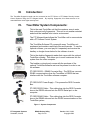
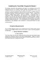
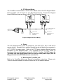
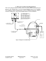
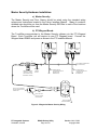
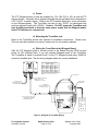
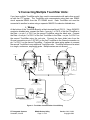
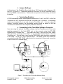
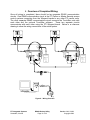
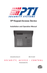
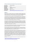
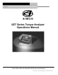
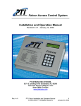
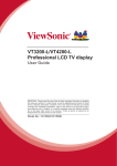
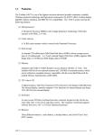
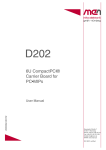
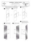
TouchStar Fingerprint Reader
Integration with PTI Access Controls
Installation and Operation Manual
Thank you for purchasing a PTI access controls system. Every effort has been made to
ensure the accuracy of the information in this document. PTI assumes no liability for
any inaccuracies contained herein. PTI reserves the right to change the information
contained herein without notice.
For the latest version of this document, contact:
PTI Integrated Systems
8271 East Gelding Drive
Scottsdale, AZ 85260
Phone 480-991-1259
Fax: 480-991-1395
Web: www.ptiaccess.com
For Technical Support Contact:
PTI Technical Support
Phone:
480-941-1513
Email:
[email protected]
Web:
http://www.ptiaccess.com/support/index.html
PTI Integrated Systems
Scottsdale, Arizona
RX900 Backup Utility
Page 2 of 23
Version 1.10 1/10/02
Copyright 2003
I. Table of Contents:
PTI Integrated Systems
Scottsdale, Arizona
RX900 Backup Utility
Page 3 of 23
Version 1.10 1/10/02
Copyright 2003
II. List of Figures:
PTI Integrated Systems
Scottsdale, Arizona
RX900 Backup Utility
Page 4 of 23
Version 1.10 1/10/02
Copyright 2003
III.
Introduction:
The TouchStar fingerprint reader can be connected to the PTI Falcon or PTI Master Security Access
Control Systems using the PTI Wiegand board. By requiring fingerprints, this allows access to be
controlled with a much higher security level.
IV.
TouchStar System Components:
This is the main TouchStar unit that the customer uses to enter
their code and verify fingerprints. This unit is not weather resistant
and should be installed in an interior environment.
The PTI Wiegand board allows the TouchStar unit to communicate
with a PTI Access Control System.
The TouchStar Software CD comes with every TouchStar unit
purchased and contains useful help files and manuals. To use the
optional software, you must pay for it separately and receive the
hardkey or dongle shown below for the software to work.
This is the desktop fingerprint reader that comes with the optional
TouchStar software. This allows you to enroll customers into the
system from the office computer.
The hardkey or dongle only comes with the purchase of the
optional TouchStar software and must be present in order to use
the software.
PTI RES RS232 – RS485 Converter Box – The RES box converts
RS485 communications from the TouchStar to RS232 that can
interface with the TouchStar software computer.
PTI RES 9VDC Power Supply – This powers the RES Converter
Box.
PTI RES RS232 Cable – This cable plugs into the RES Converter
box on the RS232 side and into the RS232 Serial port on the
computer.
PTI RES RS485 Cable – This cable plugs into the RES Converter
box on the RS485 side and into the RS485 communications of the
TouchStar system.
Figure 1 - System Components
PTI Integrated Systems
Scottsdale, Arizona
RX900 Backup Utility
Page 5 of 23
Version 1.10 1/10/02
Copyright 2003
Installing the TouchStar Fingerprint Reader:
We strongly recommend that installation and setup of all computers and any PTI
equipment be done by a certified, licensed, qualified, and competent person. PTI
Integrated Systems can recommend local dealers and installers, but it is up to the
customer to verify their qualifications and negotiate any pricing or contracts unless PTI
has been specifically contracted in writing to do so for the customer. The enclosed
information represents recommended minimum guidelines. These guidelines are
subject to change without notice. With any computer or electronics setup or
configuration, some troubleshooting and adjustment of the configuration may be
required. This will differ with every setup depending on operating system, software,
quality of computer components, internet connection, modem connection, or any other
variable introduced into the setup. This troubleshooting and configuration may include
purchasing additional equipment. In no circumstances will PTI Integrated Systems be
responsible for any damages either incidental or consequential based on these
recommendations.
A. System Requirements:
The TouchStar fingerprint reader can be installed with the PTI Falcon access control
system or the PTI Master Security access control system. Refer to the Wiring diagrams
for clarification.
1. Falcon Hardware Installation:
a) Falcon System:
The Falcon Base Unit and Door Alarms should be wired using the standard wiring
scheme and instructions located in the Falcon Installers Manual. 18awg 4 conductor
shielded wire should be run from the Falcon Base Unit RS485 terminal block to each of
the locations where the TouchStar will be used.
PTI Integrated Systems
Scottsdale, Arizona
RX900 Backup Utility
Page 6 of 23
Version 1.10 1/10/02
Copyright 2003
GRN
WHT
RED
BLK
SHIELD
GRN
DATA+
COM
DATA-
DC+
DCRED
BLK
WHT
SHIELD
GRN
WHT
RED
BLK
SHIELD
DATA+
COM
DATAGRN
RED
BLK
ORANGE
WIEGAND
BOARD
WHT
TO OTHER PTI REMOTES
(IF NECESSARY)
SHIELD
GRN
RED
TO FALCON
WIEGAND
BOARD
BLK
RED
WHITE
BLACK
GREEN
BLUE
WHT
SHIELD
DC+
DC-
b) PTI Wiegand Board:
The TouchStar communicates to the PTI Falcon Base Unit via the PTI Wiegand Board.
Each TouchStar unit will require its own PTI Wiegand board. Connect the Wiegand
board RS485 and power as shown in the PTI Falcon Installers Manual.
TO 12VDC
POWER
SUPPLY
WIRING FROM
TOUCHSTAR DEVICE
(SHOWN FOR
REFERENCE)
WIRING FROM
TOUCHSTAR DEVICE
(SHOWN FOR
REFERENCE)
Figure 2 - Wiegand to Falcon Wiring
c) Power:
The PTI Wiegand board is must be powered by 12V–18V (DC or AC) as with all PTI
remote devices. Generally this is supplied through the red and black wires connected to
a PTI 12VDC 1a power supply. Refer to the PTI Falcon Installers Manual for more
information on the Wiegand power. The TouchStar unit has its own 12VDC 1a
transformer that must be powered locally with 120VAC. Caution: Do NOT power the
TouchStar unit from the Wiegand board or from the same power supply that the
Wiegand and/or other PTI Remotes are connected to.
d) Mounting the TouchStar unit:
Refer to the TouchStar device user manual for installation instructions. Please note:
This unit must be installed in an interior location as it is not weather resistant.
PTI Integrated Systems
Scottsdale, Arizona
RX900 Backup Utility
Page 7 of 23
Version 1.10 1/10/02
Copyright 2003
e) Wiring the TouchStar to the Wiegand Board:
After the PTI Wiegand board is correctly wired to the Falcon RS485 terminal block and
power on TS1 (terminal block 1) you can connect Wiegand board to the TouchStar.
The TouchStar is wired to terminal block 2 of the PTI Wiegand board using 18AWG 4
conductor shielded wire. See the wiring diagram below for correct installation.
TOUCHSTAR TO WIEGAND
WIRING TABLE
GRN
WHT
RED
BLK
SHIELD
WIEGAND
BOARD
DATA+
COM
DATA-
DC+
DC-
FROM
TO
(Touchstar) (Wiegand)
TS2-2
CN4-43
WIRE
COLOR* FUNCTION
GREEN
DATA1
SHIELD &
GROUND
TS2-6
CN4-42
BLACK
WHITE
DATA0
TS2-3
CN4-41
RED
VERIFY
TS2-5
CN1-11
*NOTE: WIRE COLORS ARE SHOWN FOR REFERENCE
ONLY. ACTUAL WIRE COLOR MAY VARY.
TOUCHSTAR
NOTE: SHIELD & BLACK
WIRE GO INTO
TERMINAL #6 ON TS2
WIRE WITH
RED BAND
Vo
Vo
Vin
G
G
G
6
5
4
3
2
1
33
32
31
RED
11
12
13
14
15
16
17
S4
S3
S2
S1
CG
CG
CG
WI 43
Gext 42
WO 41
CN1
CN4
18GA, 4 CONDUCTOR,
SHIELDED CABLE
(RECOMMENDED).
GRN
CN16
CUT SHIELD
WIRE ON THIS END
OF CABLE ONLY.
61 Tx
62 Rx
63 G
64
65
51
52
53
TO FALCON OR
MASTER SECURITY
SYSTEM WIRING
BLK
WHT
43
42
41
Figure 3 - Wiegand to TouchStar Wiring
PTI Integrated Systems
Scottsdale, Arizona
RX900 Backup Utility
Page 8 of 23
AC ADAPTOR
(SUPPLIED W/
TOUCHSTAR)
Version 1.10 1/10/02
Copyright 2003
INPUT:
120VAC 60Hz
OUTPUT:
12VDC 1A
Master Security Hardware Installation:
a) Master Security:
The Master Security and Door Alarms should be wired using the standard wiring
scheme and instructions located in the Falcon Installers Manual. 18awg 4 conductor
shielded wire should be run from the Master Security RES Box to each of the locations
where the TouchStar will be used.
GRN
WHT
RED
BLK
SHIELD
DATA+
COM
DATAGRN
DC+
DCRED
BLK
WHT
SHIELD
GRN
WHT
RED
BLK
SHIELD
DATA+
COM
DATAGRN
RED
BLK
WIEGAND
BOARD
WHT
TO OTHER PTI REMOTES
(IF NECESSARY)
SHIELD
GRN
TO 12VDC
POWER
SUPPLY
WIRING FROM
TOUCHSTAR DEVICE
(SHOWN FOR
REFERENCE)
WIRING FROM
TOUCHSTAR DEVICE
(SHOWN FOR
REFERENCE)
RS485
TERMINAL BLOCK
(SPLICES CAN BE
USED INSTEAD OF
TERMINAL BLOCK)
9V
DC
RED
GRN (-)
WIEGAND
BOARD
BLK
RED (+)
WHT (COM)
WHT
SHIELD
DC+
DC-
b) PTI Wiegand Board:
The TouchStar communicates to the Master Security software via the PTI Wiegand
Board. Each TouchStar unit will require its own PTI Wiegand board. Connect the
Wiegand board RS485 and power as shown in the PTI Installers Manual.
RS232
PLUG INTO COM PORT
OF MASTER SECURITY
COMPUTER.
RS232 TO 9-PIN
FEMALE D-SUB
CONVERTER
RS232 TO RS485
CONVERTER BOX
Figure 4 - Wiegand to Master Security Wiring
PTI Integrated Systems
Scottsdale, Arizona
RX900 Backup Utility
Page 9 of 23
Version 1.10 1/10/02
Copyright 2003
c) Power:
The PTI Wiegand board is must be powered by 12V–18V (DC or AC) as with all PTI
remote devices. Generally this is supplied through the red and black wires connected to
a PTI 12VDC 1a power supply. Refer to the PTI Installers Manual for more information
on the Wiegand power. The TouchStar unit has its own 12VDC 1a transformer that
must be powered locally with 120VAC. Caution: Do NOT power the TouchStar unit
from the Wiegand board or from the same power supply that the Wiegand and/or
other PTI Remotes are connected to.
d) Mounting the TouchStar unit:
Refer to the TouchStar device user manual for installation instructions. Please note:
This unit must be installed in an interior location as it is not weather resistant.
e) Wiring the TouchStar to the Wiegand Board:
After the PTI Wiegand board is correctly wired to the Master Security RES box and
power on TS1 (terminal block 1) you can connect Wiegand board to the TouchStar.
The TouchStar is wired to terminal block 2 of the PTI Wiegand board using 18AWG 4
conductor shielded wire. See the wiring diagram below for correct installation.
TOUCHSTAR TO WIEGAND
WIRING TABLE
GRN
WHT
RED
BLK
SHIELD
WIEGAND
BOARD
DATA+
COM
DATA-
DC+
DC-
FROM
TO
(Touchstar) (Wiegand)
TS2-2
CN4-43
WIRE
COLOR* FUNCTION
GREEN
DATA1
SHIELD &
TS2-6
CN4-42
GROUND
BLACK
TS2-3
CN4-41
WHITE
DATA0
TS2-5
CN1-11
RED
VERIFY
*NOTE: WIRE COLORS ARE SHOWN FOR REFERENCE
ONLY. ACTUAL WIRE COLOR MAY VARY.
TOUCHSTAR
NOTE: SHIELD & BLACK
WIRE GO INTO
TERMINAL #6 ON TS2
WIRE WITH
RED BAND
CN16
CUT SHIELD
WIRE ON THIS END
OF CABLE ONLY.
Vo
Vo
Vin
G
G
G
6
5
4
3
2
1
33
32
31
11
12
13
14
15
16
17
S4
S3
S2
S1
CG
CG
CG
61 Tx
62 Rx
63 G
64
65
51
52
53
RED
WI 43
Gext 42
WO 41
CN1
CN4
18GA, 4 CONDUCTOR,
SHIELDED CABLE
(RECOMMENDED).
43
42
41
GRN
TO FALCON OR
MASTER SECURITY
SYSTEM WIRING
BLK
AC ADAPTOR
(SUPPLIED W/
TOUCHSTAR)
WHT
INPUT:
120VAC 60Hz
OUTPUT:
12VDC 1A
Figure 5 - Wiegand to TouchStar Wiring
PTI Integrated Systems
Scottsdale, Arizona
RX900 Backup Utility
Page 10 of 23
Version 1.10 1/10/02
Copyright 2003
V. Connecting Multiple TouchStar Units:
If you have multiple TouchStar units, they need to communicate with each other as well
as with the PTI system. The TouchStar units communicate using their own RS485
circuit separate RS485 from the PTI RS485 circuit. Each TouchStar unit must be
connected to another in series using a separate 18AWG 2 conductor shielded wire.
1. Wiring:
At the bottom of the TouchStar Board is a black terminal block (CN11). Using 18AWG 2
conductor shielded wire, connect the Data – from pin 1 of CN11 of the first TouchStar to
the Data – on pin 1 of CN11 on the second TouchStar using the black wire. Connect
the Data + from pin 2 of CN11 of the first TouchStar to the Data + on pin 2 of CN11 on
the second TouchStar using the red wire. Connect the bare shield wire from the
Ground connection on pin 3 of CN11 on the first TouchStar to the Ground connection on
pin 3 of CN11 on the second TouchStar. Continue this same wiring pattern to connect
the second TouchStar to any additional TouchStar units. TouchStar units must be wired
in a single, continuous, sequential series. Multiple series are not allowed.
TOUCHSTAR
CN16
6
5
4
3
2
1
CN4
RED
INPUT:
120VAC 60Hz
OUTPUT:
12VDC 1A
11
12
13
14
15
16
17
S4
S3
S2
S1
CG
CG
CG
CN1
WHT
SH
IE
RE LD
BL
D
AC
K
WI 43
Gext 42
WO 41
CN11
61 Tx
62 Rx
63 G
64
65
51
52
53
43
42
41
BLK
Vo
Vo
Vin
G
G
G
33
32
31
AC ADAPTOR
(SUPPLIED W/
TOUCHSTAR)
BLK
61 Tx
62 Rx
63 G
64
65
51
52
53
S4
S3
S2
S1
CG
CG
CG
RED
SHIELD
11
12
13
14
15
16
17
BLK
RED
CN1
CN4
33
32
31
WI 43
Gext 42
WO 41
TO WIEGAND
43
42
41
GRN
6
5
4
3
2
1
BLK
AC ADAPTOR
(SUPPLIED W/
TOUCHSTAR)
WHT
INPUT:
120VAC 60Hz
OUTPUT:
12VDC 1A
RED
SHIELD
Vo
Vo
Vin
G
G
G
GRN
CN16
TO WIEGAND
TOUCHSTAR
TO OTHER
TOUCHSTAR DEVICES
(IF NECESSARY)
BLK
RED
SHIELD
GREEN (-)
RED (+)
WHT (COM)
TERMINAL BLOCK
(SPLICES CAN BE USED
INSTEAD OF TERMINAL BLOCK)
61 Tx
62 Rx
63 G
64
65
CN11
COMPUTER
RS232 TO 9-PIN
FEMALE D-SUB
CONVERTER
ADD 120Ω TERMINATING
RESISTOR BETWEEN
TERMINALS 61 & 62 OF CN11.
PLUG INTO
SERIAL PORT
OF COMPUTER
RS232
COMPUTER FOR FALCON 2000/MASTER
SECURITY/TOUCHSTAR SOFTWARE
RS485
9V
DC
RS232 TO RS485
CONVERTER BOX
Figure 6 - TouchStar Communication Circuit Wiring
PTI Integrated Systems
Scottsdale, Arizona
RX900 Backup Utility
Page 11 of 23
Version 1.10 1/10/02
Copyright 2003
2. Jumper Settings:
At the bottom of the TouchStar Board, right above CN11 are two sets of Jumpers (J14
and J15, J16, and J17). These must all be set over pins 2 & 3 on all TouchStar units to
allow for RS485 communications. This should come preset from the factory, but should
be verified.
3. Terminating Resistor:
A 120Ω terminating resistor should placed between pins 1 and 2 on CN11 on the first
TouchStar unit in a series and on the last TouchStar unit in a series. A terminating
resistor is not required if you are only using one TouchStar unit. If you are using the
optional TouchStar software, the terminating resistor should be placed on the last
TouchStar unit farthest from the computer (linear wire distance).
4. Connecting to the TouchStar Software Computer:
If you are using the optional TouchStar software, the first TouchStar unit in the series
must be connected to the 9-pin RS32 port on the computer using the PTI RES
RS485/RS232 Converter Box.
The green wire Data – wire from the RES RS485
cable should be connected to the Data – on pin 1of CN11 terminal block on the first
TouchStar unit. The red Data + wire from the RES RS485 cable should be connected
to the Data + on pin 2 of CN11 terminal block. The white ground wire should be
connected from the RES RS485 cable should be connected to the ground connection
on pin 3 of the CN11 terminal block.
TOUCHSTAR
CN16
Vo
Vo
Vin
G
G
G
6
5
4
3
2
1
33
32
31
WHT
RED
INPUT:
120VAC 60Hz
OUTPUT:
12VDC 1A
11
12
13
14
15
16
17
S4
S3
S2
S1
CG
CG
CG
CN1
CN4
AC ADAPTOR
(SUPPLIED W/
TOUCHSTAR)
SH
IE
RE L D
BL
D
AC
K
WI 43
Gext 42
WO 41
CN11
61 Tx
62 Rx
63 G
64
65
51
52
53
43
42
41
BLK
BLK
61 Tx
62 Rx
63 G
64
65
51
52
53
S4
S3
S2
S1
CG
CG
CG
RED
SHIELD
11
12
13
14
15
16
17
BLK
RED
CN1
CN4
33
32
31
WI 43
Gext 42
WO 41
TO WIEGAND
43
42
41
GRN
6
5
4
3
2
1
BLK
AC ADAPTOR
(SUPPLIED W/
TOUCHSTAR)
WHT
INPUT:
120VAC 60Hz
OUTPUT:
12VDC 1A
RED
SHIELD
Vo
Vo
Vin
G
G
G
GRN
CN16
TO WIEGAND
TOUCHSTAR
TO OTHER
TOUCHSTAR DEVICES
(IF NECESSARY)
BLK
RED
SHIELD
GREEN (-)
RED (+)
WHT (COM)
TERMINAL BLOCK
(SPLICES CAN BE USED
INSTEAD OF TERMINAL BLOCK)
61 Tx
62 Rx
63 G
64
65
CN11
COMPUTER
RS232 TO 9-PIN
FEMALE D-SUB
CONVERTER
ADD 120Ω TERMINATING
RESISTOR BETWEEN
TERMINALS 61 & 62 OF CN11.
PLUG INTO
SERIAL PORT
OF COMPUTER
RS232
COMPUTER FOR FALCON 2000/MASTER
SECURITY/TOUCHSTAR SOFTWARE
RS485
9V
DC
RS232 TO RS485
CONVERTER BOX
Figure 7 - TouchStar unit to TouchStar Software Wiring
PTI Integrated Systems
Scottsdale, Arizona
RX900 Backup Utility
Page 12 of 23
Version 1.10 1/10/02
Copyright 2003
5. Overview of Completed Wiring:
Once all wiring is completed, there should be two separate RS485 communication
circuits. One RS485 communication circuit is the PTI Falcon or Master Security access
control systems connecting from the Wiegand boards to any other PTI remote units.
The other separate RS485 communications circuit connects the TouchStar units with
each other and the optional TouchStar software. These two separate circuits
communicate with each other using the PTI Wiegand board. Below is a reference
drawing to show the wiring connections of the entire system.
WIEGAND
BOARD
S4
S3
S2
S1
CG
CG
CG
COMPUTER FOR FALCON 2000/MASTER
SECURITY/TOUCHSTAR SOFTWARE
43
42
41
CN4
BLK
WHT
RED
INPUT:
120VAC 60Hz
OUTPUT:
12VDC 1A
RS232
11
12
13
14
15
16
17
S4
S3
S2
S1
CG
CG
CG
RS485
Figure 8 – Wiring Overview
RX900 Backup Utility
Page 13 of 23
Version 1.10 1/10/02
Copyright 2003
43
42
41
GRN
6
5
4
3
2
1
WI 43
Gext 42
WO 41
CN11
9V
DC
PTI Integrated Systems
Scottsdale, Arizona
Vo
Vo
Vin
G
G
G
33
32
31
AC ADAPTOR
(SUPPLIED W/
TOUCHSTAR)
CN1
11
12
13
14
15
16
17
61 Tx
62 Rx
63 G
64
65
51
52
53
RED
CN1
CN4
33
32
31
WI 43
Gext 42
WO 41
CN16
6
5
4
3
2
1
61 Tx
62 Rx
63 G
64
65
51
52
53
Vo
Vo
Vin
G
G
G
GRN
CN16
WIEGAND
BOARD
BLK
AC ADAPTOR
(SUPPLIED W/
TOUCHSTAR)
WHT
INPUT:
120VAC 60Hz
OUTPUT:
12VDC 1A
VI.
Setting Up the TouchStar Unit(s):
The TouchStar units must be configured to work together with each other and with the
PTI system. Follow the steps below to complete this process for each and every
TouchStar unit.
1. Master Code:
The TouchStar unit is shipped from the factory without a Master code entered into it.
The only way to program they system, change the setup, or enroll users is with a Master
code. Once you have enrolled one Master code, you can enroll additional Master
codes. To enter a master code, press the right-most button on the TouchStar face, four
times. This is the button with a blue ring around it.
Caution: if you lose the Master code or if the person whose fingerprint is
enrolled with the Master code is not available; the only way to reprogram
the Master code is with the optional TouchStar software that must be
purchased from PTI.
Note: PTI Dealers may enter a Master code for initial setup, but MUST
enroll a site representative (owner or manager) and delete the dealer
Master code prior to leaving the site.
a) The system will ask you to enter a Master ID. This should be a four digit code
that will not be used by a customer.
b) The system will then ask you to place your finger on the platen. Hold your
finger still while the system quickly scans the fingerprint.
c) The system will then ask you to lift your finger briefly and then place it back
on the platen for verification.
d) Once the fingerprint is verified, the system will let you know that it is
accepted.
PTI Integrated Systems
Scottsdale, Arizona
RX900 Backup Utility
Page 14 of 23
Version 1.10 1/10/02
Copyright 2003
2. System Setup:
The Wiegand output on the TouchStar unit will need to be configured before the
interface will work. To configure the Wiegand output, log on to the TouchStar with a
Master.
a) At the main screen, press the ‘SEL button to highlight the “CONFIG” option
and press the ‘Enter’ Button. In the System Config screen, press the Page
button to turn to the next page.
b)
Press the ‘SEL’ button to select the ‘Wiegand’ option and press ‘Enter’.
c) Press the ‘SEL’ button until the format shows ’26 Bits-V1’ then press the
Enter button. Then press the ‘SEL’ button until the Wiegand Out shows
‘Enable’. Press ‘Enter’ again. Last, press the ‘SEL’ button until the Site Code
is ‘0000’ and press enter. Once the settings are correct, press the ‘Exit’
button and select ‘Yes’ when prompted to save the settings.
d) They TouchStar should now be on the System Config Screen. If not, repeat
step ‘a’ above. In the System Config screen, select ‘Ext.In’ and press enter.
PTI Integrated Systems
Scottsdale, Arizona
RX900 Backup Utility
Page 15 of 23
Version 1.10 1/10/02
Copyright 2003
e) Press the “SEL” button until enable shows “[YES]” then press the “ENTER”
button. Now press the “SEL” button until the Type shows “WIEGAND ACK”
then press the “ENTER” button. Next, press the “SEL” button until the
Timeout shows “3.0” then press the “ENTER” button. Now press the “EXIT”
button and select “YES” when prompted to save the changes. The TouchStar
is now configured for use with the PTI Falcon system. If the customer is
using the TDM Deluxe software, make sure the settings in the software match
those just configured. If the settings are changed, the TouchStar will not work
properly with the PTI system.
3. Setting Device ID’s:
The Wiegand output on the TouchStar unit will need to be configured before the
interface will work. To configure the Wiegand output, log on to the TouchStar with a
Master.
a) At the main screen, press the ‘SEL button to highlight the “CONFIG” option
and press the ‘Enter’ Button. In the System Config screen, press the Page
button to turn to the next page.
b) At the System Config screen, select ‘comm’ and press the ‘Enter’ button.
c) At the Set Comm screen, select ‘Type’ and press the ‘Enter’ button.
d) Verify that the comm type is RS485 and press the ‘Enter’ button.
PTI Integrated Systems
Scottsdale, Arizona
RX900 Backup Utility
Page 16 of 23
Version 1.10 1/10/02
Copyright 2003
e) At the Config RS485 screen, press the ‘Select’ button to change the setting to
‘Customize‘. Press ‘Enter’ and set the baud rate. This must be same on
every Touchstar device and in the TouchStar software also. Press ‘Enter’
and set the ‘Comm id’. This is just like the address on a PTI remote. These
comm id’s must be in sequential order from the first TouchStar unit in line to
the last TouchStar unit in line with no duplication.
f) After all settings are correct, press the ‘Exit’ and select ‘Yes’ to save the
setting. Repeat these steps with every TouchStar unit.
PTI Integrated Systems
Scottsdale, Arizona
RX900 Backup Utility
Page 17 of 23
Version 1.10 1/10/02
Copyright 2003
VII.
Programming the TouchStar Software
If you purchased the optional TouchStar Device Manager software, it must be installed
on the computer in the office. Generally, this is the same computer that the Falcon
2000 or Master Security software is installed on.
1. Hardkey or Dongle:
With each TouchStar Software purchased, you will receive a Hardkey or Dongle. This
device plugs into the parallel port on the back of the computer and must be present or
the software cannot be used.
2. Opening the TouchStar Software:
Open the TouchStar software using the ‘Supvisor’ code. Refer to the TouchStar help
files on the TouchStar software for more information.
3. Opening the TouchStar Software:
Click on the TouchStar menu in the toolbar at the top of the screen and select Device
Management System from the dropdown menu. In the Device Management screen,
you must ‘Add Devices’ for each TouchStar unit connected to the software and you
must enter the ‘Set Device Properties’ screen on each device to enable the Wiegand
input, set it to 26 Bits-V1, set the site code to 0000, set the Wiegand ACK, Timeout 2.0,
Baud Rate, and Comm ID, as set above for each device.
4. Using the Software:
Open Refer to the TouchStar help files on the TouchStar software for further software
setup and use.
PTI Integrated Systems
Scottsdale, Arizona
RX900 Backup Utility
Page 18 of 23
Version 1.10 1/10/02
Copyright 2003
VIII.
Enrolling Customers into the System
Because the TouchStar system maintains its own separate database, you must enroll
the clients fingerprints and proximity cards in the TouchStar system and then enroll their
code and unit information into the PTI Falcon, Falcon 2000, or Master Security System.
1. Reserved Codes:
The TouchStar system has reserved the codes 0001 – 0010 for their own system
messages. Therefore, make sure that no customers in the Falcon or Master Security
system have those as assigned access codes. You must create ten false units in the
Falcon system and assign those access codes. These ten false units must then be
suspended to prevent accidental entry onto the site from invalid attempts.
The TouchStar device will report an invalid match (fingerprints don’t match) to the
Falcon as a user code of 0001. It will report an invalid card or code entry as a user
code of 0002, and it will report a validation fail (no response or no match after two
attempts) as a user code of 0003. To make these events meaningful, each of these
codes can be assigned to false units in the Falcon 2000 or Master Security database
and those units suspended. The unit description would then be entered as the
description of the user code reported. For example, units of S0001 to S0003 could be
used for system events. All of these units would be suspended to prevent access from
being granted.
Unit S0001 would be assigned access code of 0001 and the description for the unit
would be entered as “No Fingerprint Match” or as “Invalid Fingerprint”. Events for this
unit will then print that description on reports.
Unit S0002 would be assigned access code of 0002 and the description for the unit
would be entered as “Invalid ID Code” or “Invalid ID Card”. Events for this unit would
then print that description on reports.
Unit S0003 would be assigned access code of 0003 and the descriptions for the unit
would be entered as “Validation Failed”. That description would then print on the
reports.
The TouchStar will report an Invalid Fingerprint code every time the finger does not
match its database. The TouchStar will allow a user to try the fingerprint a second time
if it does not match on the first try. It will still report the first try to the Falcon with a user
code of 0001. After the second try, if the fingerprint still does not match, it will report a
validation failed to the Falcon with a user code of 0003.
If a user attempts to enter an invalid code on the TouchStar, it will report an Invalid ID to
the Falcon with a user code of 0002.
PTI Integrated Systems
Scottsdale, Arizona
RX900 Backup Utility
Page 19 of 23
Version 1.10 1/10/02
Copyright 2003
2. Communication with the Falcon or Master Security:
Because the TouchStar database is separate from the PTI database, the TouchStar will
wait for the Falcon or Master Security to respond before granting access. When it
sends a user code to the Falcon or Master Security that is valid in the TouchStar
database, it will wait for the PTI system to respond. If that user code is valid, the PTI
system will respond to the TouchStar and the user will be granted access. If the user
code sent by the TouchStar is not valid in the PTI database, the PTI system will report
the invalid access attempt (Unknown Code, Suspended, area denied, etc.) The PTI
system will also not respond to the TouchStar. After the timeout period, the TouchStar
will report a Validation Fail to the PTI system with a user code of 0003.
In order for a valid TouchStar user to gain entry to the facility and have their door
disarmed, the user identification that is sent out from the TouchStar via the Wiegand
interface will need to be entered in the PTI system. If the data is not entered carefully,
the user will get a valid access message from the TouchStar but will not be allowed
access to the facility. Because of the configuration, two different systems and
databases will need to be maintained for the system to operate properly.
NOTE: Enrollment of fingerprints and cards will have to be done through the TouchStar
system software and not the PTI Falcon or Master Security. Refer to the TouchStar
manual for these instructions. The code will then need to be entered into the PTI
Falcon or Master Security.
PTI Integrated Systems
Scottsdale, Arizona
RX900 Backup Utility
Page 20 of 23
Version 1.10 1/10/02
Copyright 2003
IX.
Troubleshooting:
Occasionally, you may run into situations where the RX900 Utility is not functioning
correctly. Try these troubleshooting steps. If you are still having problems after trying
these steps, contact PTI technical support at (480) 941-1513 or by email at
[email protected].
A. TouchStar doesn’t communicate with PTI:
1. Verify all wiring connections.
2. Verify all settings in each TouchStar and in the TouchStar
software (Wiegand input, set it to 26 Bits-V1, set the site code to
0000, set the Wiegand ACK, Timeout 2.0, Baud Rate, and Comm
ID).
3. Have a knowledgeable technician troubleshoot the system.
B. TouchStar units don’t communicate:
1. Verify all wiring connections.
2. Verify all settings in each TouchStar and in the TouchStar
software (Wiegand input, set it to 26 Bits-V1, set the site code to
0000, set the Wiegand ACK, Timeout 2.0, Baud Rate, and Comm
ID).
3. Have a knowledgeable technician troubleshoot the system.
C. TouchStar acknowledges client but gate or door
doesn’t open:
1. Verify all wiring connections.
2. Verify that the client’s code is not 0001 – 0010.
3. Verify that client is setup in both databases.
4. Verify that PTI system and TouchStar system are communicating.
PTI Integrated Systems
Scottsdale, Arizona
RX900 Backup Utility
Page 21 of 23
Version 1.10 1/10/02
Copyright 2003
X. Warranty & Disclaimer:
For TouchStar equipment, TouchStar’s Warranty applies. All warranty issues must be
referred to their company. For PTI manufactured equipment, the Warranty below
qualifies:
PTI Integrated Systems (PTI) warrants products and equipment manufactured by PTI to
conform to its own specifications and to be free from defects in materials and
workmanship, under normal use and service, for a period of two years from the date of
shipment. Within the warranty period, PTI will repair or replace, at its option, all or any
part of the warranted product which fails due to materials and / or workmanship. PTI
will not be responsible for the dismantling and / or re-installation charges. To utilize this
warranty, the User must be given a Return Material Authorization (RMA) number by
PTI. The User must pay all shipping costs for returning the product to PTI.
This warranty does not apply in cases of improper installation, misuse, failure to follow
the installation and operating instructions, alteration, abuse, accident, tampering, natural
events (lightning, flooding, storms, etc.), and repair by anyone other than PTI.
This warranty is exclusive and in lieu of all other warranties, expressed or implied,
including but not limited to the implied warranties of merchantability and fitness for a
particular purpose. PTI will not be liable to anyone for any consequential or incidental
damages for breech of this warranty or any other warranties.
This warranty will not be modified, varied or extended. PTI does not authorize any
person to act on its behalf to modify, vary or extend this warranty. This warranty applies
to PTI products only. All other products, accessories, or attachments used in
conjunction with PTI equipment, including batteries, will be covered solely by their own
warranty, if any. PTI will not be liable for any direct, incidental or consequential damage
or loss whatsoever, caused by the malfunction of product due to products, accessories,
or attachments of other manufacturers, including batteries, used in conjunction with PTI
products.
This warranty does not warrant the replacement of batteries that are used to power PTI
products.
The User recognizes that a properly installed and maintained security system may only
reduce the risk of events such as burglary, robbery, personal injury, and fire. It does not
insure or guarantee that there will be no death, personal damage, and / or damage to
property as a result. PTI does not claim that the Product may not be compromised
and / or circumvented, or that the Product will prevent any death, personal and /
or bodily injury and / or damage to property resulting from burglary, robbery, fire,
or otherwise, or that the Product will in all cases provide adequate warning or
protection.
PTI Integrated Systems
Scottsdale, Arizona
RX900 Backup Utility
Page 22 of 23
Version 1.10 1/10/02
Copyright 2003
PTI shall have no liability for any death, injury or damage, however incurred,
based on a claim that PTI Products failed to function. However, if PTI is held liable,
directly or indirectly, for any loss or damage arising under this limited warranty or
otherwise, PTI’s maximum liability will not in any case exceed the purchase price of the
Product, which will be fixed as liquidated damages and not as a penalty, and will be the
complete and exclusive remedy against PTI.
Warning: The User should follow all installation, operation, and maintenance
instructions. The User is strongly advised to conduct Product and systems test at
least once each week. Changes in environmental conditions, electric or electronic
disruptions and tampering may cause the Product to not perform as expected.
Warning, PTI warrants its Product to the User. The User is responsible for
exercising all due prudence and taking necessary precautions for the safety and
protection of lives and property wherever PTI Products are installed. PTI does not
authorize the use of its Products in applications affecting life safety.
Notice. The PTI wireless door alarm system uses 900Mhz technology. Other devices
at the site such as cordless telephones or alarm components may cause interference
that will disrupt the operation of the system or may be interfered with by the system.
PTI assumes no liability for any problems caused by interference. It is the sole
responsibility of the user to identify and correct such problems.
PTI Integrated Systems
Scottsdale, Arizona
RX900 Backup Utility
Page 23 of 23
Version 1.10 1/10/02
Copyright 2003