1
ZEUS MVD PLC-CAN interface
v1.4 19-Feb-2001
1 Introduction
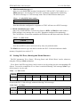
The CAN-fieldbus network that interconnects (a number of) the MVD control systems and
the MVD-Controls Supervisor is used by the Supervisor to monitor and control the various
MVD subsystems. One of the subsystems connected to the CAN network is the PLCcontrolled cooling system of the MVD frontend-electronics.
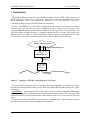
The PLC (SIEMENS S7) of the MVD cooling system does not have an interface to connect
it directly to a CAN-bus. But it does have an RS232 interface, which is used to connect it to a
so-called SPICAN module which features an RS232 interface as well as a CAN interface. The
SPICAN module can thus provides an interface between the PLC and the CAN network, as
illustrated below in Figure 1. Custom application firmware has been developed for the SPICAN module to provide a communication interface between RS232 and CAN-bus.
MVD Cooling System
digital and analog I/O
PLC
(SIEMENS S7)
RS232
PLC-CAN
(SPICANmodule)
CAN-bus
Figure 1. Interface of MVD Cooling System to CAN-bus.
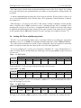
A protocol has been agreed upon for transfer of data and commands via the RS232 conne ction between the application running on the SPICAN module (PLC-CAN) and the PLC application (see "
APPENDIX C Protocol on the PLC-CAN↔PLC" for a description). The PLC-CAN application maps messages to and from the PLC application onto appropriate CAN-messages. This
document provides a detailed description of the interface to the PLC seen from the CAN-bus
side.
The protocol used on the MVD CAN-network is CANopen ([1]). This document assumes
that the user has at least a basic knowledge of this protocol.
2