1
FA116
Executive Programmer
User Manual
01860
for FA416, FA426 and FA464
Frequency Agile® Receivers
and
C404 4-channel slave receiver
© 1997 INOVONICS Corporation
LIT-FA116-USER 01860.DOC
Table of Contents
Overview................................................Page 1
Features ......................................Page 1
Dimensions.................................Page 1
Programming FA416 & FA464 .............Page 2
Point Status ................................Page 2
Receiver Setup ...........................Page 3
Output Setup ..............................Page 4
Program Points ..........................Page 5
Delete Points ..............................Page 6
Clear Faults ................................Page 6
Test Outputs...............................Page 6
Programming C404...............................Page 7
Point Status ................................Page 7
Receiver Setup ...........................Page 7
Program Points ..........................Page 8
Delete Points ..............................Page 9
Programming FA426.............................Page 10
Clear Points ................................Page 10
Delete Points ..............................Page 10
Program Points ..........................Page 11
Appendix A: FA416 Defaults ................Page 12
Appendix B: FA464 Defaults ................Page 13
Appendix C: C404 Defaults ..................Page 15
Appendix D: Recommended Transmitter
Programming..................Page 16
Appendix E: Warranty ..........................Page 18
© 1997 INOVONICS Corporation
01860 LIT-FA116-USER
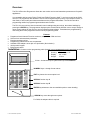
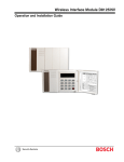
Overview:
The FA116 Executive Programmer allows the user to alter receiver and transmitter parameters to fit specific
applications.
It is compatible with Inovonics FA416, FA426 and FA464 Frequency Agile™ receivers as well as the C404
receiver. The programmer also allows the user to monitor signal margin of points, to test output functions, to
clear faults, to add, modify and delete transmitters and to program transmitters. The FA116 has built-in
programming cables for programming transmitters and receivers.
The FA116 is menu-driven. Users locate main menu headings using arrow keys, then select headings by
pressing the ENTER key. The programmer displays option screens which allow the user to accept, change or
reject current settings for the receiver, receiver outputs and transmitters. Transmitters are programmed by
connecting them to the programmer via the built-in programming cable.
x
x
x
x
x
x
x
Features
Programs all multi-channel FA-series receivers; adaptable for C404 receivers.
Sets receiver and transmitter parameters.
Permits transmitter zoning.
Programming cables store in rear compartment.
Available C404 adapter: stereo jack to 4-pin header. (Not included.)
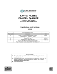
16-Key tactile keypad.
Built-in bench stand.
Installation: Connect receiver programming cable (located in rear compartment) to mini stereo jack on receiver.
x
x
x
Housing:
Display:
Weight:
Dimensions
7.0" x 3.9" x 1.75"
2.4" x .625"
10.9 oz.
2-Line x 16-character liquid crystal backlit supertwist DISPLAY.
NUMERIC keys 1 through 0 enter values.
1
2
3
4
5
6
A
7
8
9
B
EXIT
EXIT key leaves the current option level.
SPECIAL function key A.
SPECIAL function key B.
0
ENTER
ENTER key advances to the next available option or menu heading.
ARROW keys move through menu options.
For C404, the adapter cable is required.
© 1997 INOVONICS Corporation
1
LIT-FA116-USER 01860
Programming FA416 and FA464 Receivers
with the FA116 Executive Programmer
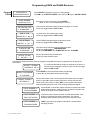
Following are descriptions of menu and option displays. Main menu headings are POINT STATUS, RECEIVER
SETUP, OUTPUT SETUP, PROGRAM POINT, DELETE POINT, CLEAR FAULTS and TEST OUTPUTS.
When the FA116 is first powered up, the display briefly shows software version information, then shows the logo
display, including receiver type:
INOVONICS FA416
INOVONICS FA464
FREQUENCY AGILE
FREQUENCY AGILE
To enter programming mode, enter the access code. Default access code is 3446. The display will show:
Point
Status
Press ENTER for
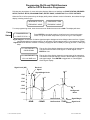
Press ENTER to see signal margins, signal levels and current point status.
Press Å to go to Receiver Setup menu or press Æ to go to Test Outputs.
Å POINT STATUS Æ
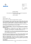
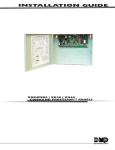
Signal margin is an indicator of relative signal strength to background noise. Margin values are from 3 (signal
just distinguishable from background) to 33 (strongest). Signal margins below 10 are reported as "Weak".
Signal level is an absolute measure of intensity, ranging from about -65dB (very strong) to below -110dB (very
faint).
Å1 ALM TMP BATTÆ
GOOD SIGNAL
The top line of the display shows the current status of the transmitter.
The second line will read "Good Signal" or "Weak Signal". Press
ENTER to view
Å1 ALM TMP BATTÆ
LVL:-nnn MAR:+mm
The top line of the display shows the current status of the transmitter.
The bottom line shows real-time values in dB and dBm for signal level
and signal margin. Press ENTER to toggle back to "Good Signal /
Weak Signal" display.
`
Received
Signal
Signal Level (dB)
33
Signal Margin Scale
33
-65dB
33
-75dB
-85dB
3
-95dB
3
-105dB
Background
Noise
3
-115dB
© 1997 INOVONICS Corporation
33
10
-65dB
-100dB
Not Received
18
Not Received -75dB
2
Signal Margin
Signal Level
LIT-FA116-USER 01860
Programming FA416 and FA464 Receivers
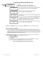
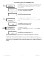
Receiver
Setup
Press ENTER for
Å RCVR SETUP Æ
Press ENTER to review or to modify receiver settings.
Press Å to go to Output Setup menu or Æ for Review Points.
System ID is encoded in all data transmissions to identify transmitters
to their respective receivers. Enter a code from 000 to 255.
SYSTEM ID: 123
SUPERVISE POINTS
Å
YES
Æ
MAX TX INACTIVE
TIME: 4 Å HRS Æ
3446
VISION COMPATIBLE
NO
How long should the receiver wait for a supervisory signal to declare
points inactive?
Enter value from 1 to 99. Arrow keys toggle between MIN and HRS.
To change dealer access code enter number from 0000 to 9999.
(3446 is default.) Note: Default access code may be reset ONLY by
restoring receiver to factory defaults. See below.
ACCESS CODE
Å
Should the receiver monitor transmitters for inactivity?
Arrow keys toggle between YES and NO.
Æ
Should the receiver look for transmitter data for Vision Plus systems?
Arrow keys toggle between YES and NO.
Reminder: Press ENTER to advance to next menu option. ENTER accepts data in display and proceeds.
What is "Vision Plus Compatibility"?
Vision Plus Compatibility permits transmitters programmed by a the Vision Plus panel to be monitored by an
FA416 or an FA464 receiver AS LONG AS BOTH SYSTEMS HAVE THE SAME SYSTEM ID.Transmitters
monitored by FA receivers need not be programmed by the receiver. Once the receiver hears a Vision Plusprogrammed transmitter, the receiver will consider it one of its own. (Note: any transmitters programmed by
an FA416 receiver will NOT be received by a Vision Plus .)
Initializing FA416 or FA464 receivers: The following sequence will restore the receiver to factory default
settings: (ADV, RESET and DEL Buttons are located on the receiver.)
1. Press and Hold ADV.
2. Press and release RESET.
3. Release ADV.
4. Immediately, while the Decode and Valid LEDs are off, press and hold DEL for 6 to 7 seconds.
5. The receiver will flash the TX PRGM LED, indicating restoral complete.
Refer to appropriate appendices for factory default settings.
© 1997 INOVONICS Corporation
3
LIT-FA116-USER 01860
Programming FA416 and FA464 Receivers
Output
Setup
Press ENTER for
Å OUTPUT SETUP Æ
Press ENTER to review or to modify output settings.
Press Å to go to PROGRAM POINTS menu option or Æ to go to RCVR
SETUP.
OUTPUT nn:
Å
ALARM
Æ
Press ENTER to advance through all numbered outputs.
Press Å or Æto select from options ALARM,
ALARM+TAMPER, TAMPER, LO BATT, INACTVE,
TAMP+LOBATT, TAMP+INACTVE, BATT+INACTVE, ANY
TX FAULT, and DISABLED.
Note: ALARM and ALARM+TAMPER are point-specific: points programmed to a given output will trip the
output if alarmed or if tampered. All other fault options are global; i.e., any listed fault (or combination of faults)
will cause the output to activate. Attempts to assign duplicate global fault conditions to other outputs are not
allowed.
OUTPUT 1: GLOBL
Å TAMP+LO BATT Æ
Global faults will be indicated.
If an output is modified to function as a global fault output and is currently assigned as alarm to an active point,
the user will be prompted for permission to re-assign the output:
Note: an output cannot activate
OUTPUT 1 IN USE
based on both fault and alarm
conditions.
REASSIGN?Å YES Æ
When output setup is complete, points affected by re-assignment will be shown.
CHECK POINT
1
OUTPUT ASSIGNM'T
Note: "Follower" outputs go on and off as the transmitter changes between alarm and secure states. "Latching"
outputs go on at first activation, and stay on until reset. "Momentary" outputs go on for a prescribed
duration then turn off, regardless of what the transmitter does after first activation.
ALARM OUTPUTS
Å
FOLLOWER
Æ
Press Å or Æ to select from options FOLLOWER, MOMENTARY or
LATCHING.
Æ
Press Å or Æ to select from options FOLLOWER, MOMENTARY or
LATCHING.
TAMPER OUTPUT
Å
FOLLOWER
LO BATT OUTPUT
Å
LATCHING
Æ
INACTIVE OUTPUT
Å
FOLLOWER
Æ
Press Å or Æ to select from options FOLLOWER, MOMENTARY or
LATCHING.
Press Å or Æ to select from options FOLLOWER, MOMENTARY or
LATCHING.
If any outputs are programmed MOMENTARY, the user will be prompted for the number of seconds of
momentary activation.
MOMENTARY OUTPUT
TIME:
© 1997 INOVONICS Corporation
Enter a value from 1 to 16 seconds.
4 secs
4
LIT-FA116-USER 01860
Programming FA416 and FA464 Receivers
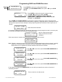
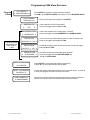
Program
Points
Press ENTER to
ÅPROGRAM POINTÆ
POINT NUMBER:
ENTER #(1 to nn)
EXT SWITCH TYPE
Å NORM/OPEN Æ
END OF LINE
RESISTOR: Å NO Æ
USE INTERNAL
CONTACT: Å NO Æ
CHECK-IN TIME
Å 60 SECONDS Æ
OUTPUT TO USE:
Å OUTPUT 1 Æ
Press ENTER to program a point or to modify settings.
Press Å to go to DELETE POINTS menu option or Æ to go to OUTPUT SETUP.
Enter point number from keypad. Press ENTER.
(Note: nn=16 or nn=64, depending on receiver.)
Is the external transmitter switch loop Normally Open or Closed?
Arrow keys toggle between N/O and N/C.
Is a 2.2K end of line resistor being used?
Arrow keys toggle between YES and NO.
Is the FA200W widegap magnet contact being used?
Arrow keys toggle between YES and NO.
How often should transmitters send supervisory data?
Arrow keys toggle between UNSUPERVISED,
10, 30, or 60 SECONDS, 5 or 60 MINUTES and 8 or 18 HOURS.
Which output should this point activate?
Arrow keys select desired output.
If the selected output has been previously assigned as a global fault output, the programmer will prompt for
confirmation:
It is recommended that the output be redefined as an alarm, or
OUTPUT n GLOBAL
that the point be assigned to another output. Arrow keys toggle
CONFIRM?Å YES Æ
between YES and NO.
ENTER TO PROGRAM
Press ENTER to proceed with transmitter programming.
or press A to go through transmitter options again.
"A" to REVIEW
CONNECT TX+RESET
OR PRESS "A"
Connect transmitter to the FA116 and press transmitter reset to program
device, or press A to save program information, activate the point and
select a new point number, or press EXIT to save program information
without activating the point. One of the following displays will appear:
POINT NUMBER nn
TX PROGRAMMED
POINT NUMBER nn
POINT ACTIVATED
POINT NUMBER nn
PROGRAM SAVED
© 1997 INOVONICS Corporation
If a transmitter is connected, display indicates successful transmitter
programming sequence. Display remains for about 3 seconds, then
returns to the point number selection screen.
If special key A is pressed, the point is saved and activated, even
though no transmitter has been programmed. This may be
necessary when replacing receivers or when using the FA100.
If EXIT is pressed, point program information is saved without
activating the point.
5
LIT-FA116-USER 01860
Programming FA416 and FA464 Receivers
Delete
Points
Press ENTER to delete a point. Programming remains in memory, but the
receiver will not look for the point. To reactivate the point, go to Program
Points. Press Å to go to CLEAR FAULTS menu option or Æ to go to
PROGRAM POINT.
Press ENTER to
Å DELETE POINT Æ
POINT NUMBER:
Enter point number from keypad. Press ENTER.
(nn = 16 or nn = 64, depending on receiver.)
ENTER #(1 to nn)
At this point the programmer requests confirmation:
ARE YOU SURE?
Å
Clear
Faults
NO
Æ
Faults may be registered during programming and operation.
Press ENTER to clear latched fault outputs.
Press Å to go to TEST OUTPUTS menu option or Æ to go to DELETE
POINT.
Press ENTER to
Å CLEAR FAULTS Æ
ARE YOU SURE?
Å
Test
Outputs
YES
Æ
Press ENTER to
ENTER to TOGGLE
OUTPUT 1
Press ENTER to accept answer in next line.
Arrow keys toggle between YES and NO.
Press ENTER to test outputs.
Press Å to go to POINT STATUS menu option or Æ to go to CLEAR
FAULTS.
Å TEST OUTPUTS Æ
Å
Press ENTER to accept answer in next line.
Arrow keys toggle between NO and YES.
Æ
Press ENTER to turn selected output on and off.
Press Å or Æ to select a different output.
Note: The FA416 has 4 outputs, plus the fault output. The FA464 has 16 outputs, plus the fault output.
Creating Zones with the FA116: By assigning transmitter alarm conditions to specific alarm outputs, it is
possible to differentiate between types of alarms, areas of alarms, etc. For example, suppose an application in a
small business requires 10 holdup buttons, 1 fire exit door and 3 removable pendants. Program outputs 1, 2 and
3 to be active on alarm and program the FA200s attached to the holdup buttons to use output 1. Assign the fire
exit point to output 2 and the pendants to output 3. Configure the system to monitor low batteries and tampers at
output 4.
© 1997 INOVONICS Corporation
6
LIT-FA116-USER 01860
Programming C404 Slave Receivers
with the FA116 Executive Programmer
Following are descriptions of menu and option displays. Main menu headings are POINT STATUS, RECEIVER
SETUP, PROGRAM POINT, and DELETE POINT.
When the FA116 is first powered up, the display briefly shows software information, then shows the logo display,
including receiver type.
INOVONICS C404
SLAVE RECEIVER
To enter programming mode, enter the access code. Default access code is 0000. The display will show:
Point
Status
Press ENTER for
Å POINT STATUS Æ
Press ENTER to see signal strength and current point status.
Press Å to go to RECEIVER SETUP menu or Æ for DELETE POINT.
Å1: ALM TMP B Æ
GOOD SIGNAL (-nn)
Receiver
Setup
Press ENTER for
Å RCVR SETUP Æ
Press ENTER to review or to modify receiver settings.
Press Å to go to PROGRAM POINT menu or Æ for REVIEW POINTS.
System ID is encoded in all data transmissions to identify transmitters
to their respective receivers. Enter a code from 000 to 255.
SYSTEM ID: 123
SUPERVISE POINTS
Å
The first line shows point status, including a low battery symbol. The
value beside the GOOD SIGNAL or WEAK SIGNAL is dBm above
receiver threshold level, from -99 (weak) to -65 (strong).
YES
Æ
MAX TX INACTIVE
TIME: 60 MINUTES
Should the receiver monitor transmitters for inactivity?
Arrow keys toggle between YES and NO.
How long should the receiver wait for a supervisory signal to declare
points inactive?
Enter value from 1 to 254 minutes.
Change dealer access code, if desired.
Enter access code from 0000 to 9999. (0000 is default.)
ACCESS CODE
0000
WARNING:The C404 access code cannot be recovered or reset if
lost.
ALARM OUTPUTS :
Å
FOLLOWER
Æ
Set mode of all C404 ALARM outputs. Arrow keys select option:
FOLLOWER, LATCHING or MOMENTARY.
Press Å or Æ to change option.
Note: This setting affects all of the C404's alarm outputs. The
C404 global fault output is always latching.
© 1997 INOVONICS Corporation
7
LIT-FA116-USER 01860
Programming C404 Slave Receivers
Program
Points
Press ENTER to
Press ENTER to program or modify transmitter settings.
Press Å to go to DELETE POINTS menu option or Æ for RECEIVER SETUP.
Å PROGRAM POINTÆ
POINT NUMBER:
ENTER #(1 to 4)
4-BUTTON TX:
Å
YES
Æ
EXT SWITCH TYPE
Å NORM/OPEN Æ
END OF LINE
THESE OPTIONS
ARE SKIPPED IF
4-BUTTON TX
= "YES"
RESISTOR: Å NO Æ
USE INTERNAL
CONTACT: Å NO Æ
CHECK-IN TIME
Å 60 SECONDS Æ
ENTER TO PROGRAM
"A" to REVIEW
RESET TX+CONNECT
OR PRESS "A"
POINT NUMBER nn
TX PROGRAMMED
© 1997 INOVONICS Corporation
Enter point number from keypad. Press ENTER.
Is the transmitter a C100 Commander?
Arrow keys toggle between YES and NO.
Is the external switch loop normally open or closed?
Arrow keys toggle between NORM/OPEN and NORM/CLOSED.
Is a 2.2K end of line resistor being used to monitor the switch loop?
Arrow keys toggle between NO and YES.
Is C200W widegap magnet contact being used? Arrow keys toggle
between NO and YES.
How often should supervisory data be transmitted?
Arrow keys toggle between UNSUPERVISED and
10, 30, or 60 SECONDS.
Press ENTER to proceed with transmitter programming,
or press A to go through transmitter options again.
Connect transmitter and press transmitter reset to program device, or press A
to save point program and select a new point number.
Indicates successful transmitter programming sequence. Display remains for
about 3 seconds, then returns to the point number selection screen.
8
LIT-FA116-USER 01860
Programming C404 Slave Receivers
Delete
Points
Press ENTER to
ÅDELETE POINT Æ
Press ENTER to program a point or to modify settings.
Press Å to go to POINT STATUS menu option or Æ to go to PROGRAM POINT.
POINT NUMBER:
ENTER # (1 to 4)
Enter point number from keypad. Press ENTER.
At this point the programmer requests confirmation:
ARE YOU SURE?
ÅYES
POINT NUMBER: nn
DELETED
Arrow keys toggle between YES and NO.
Æ
Indicates successful point deletion. (Display remains for about 3 seconds, then
returns to the point number selection screen.)
Note: Programming parameters are not erased from receiver memory.
Transmitters may be re-programmed to the deleted point number.
© 1997 INOVONICS Corporation
9
LIT-FA116-USER 01860
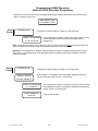
Programming FA426 Receivers
with the FA116 Executive Programmer
When the FA116 is first powered up, the display briefly shows software information, then shows the logo
display, including receiver type.
DMP MODEL FA426
FREQUENCY AGILE
Clear
Points
SYSTEM ID: nnn
Progammer requests System ID. nnn = 0 to 255 (decimal).
ENTER TO PROGRAM
"A" TO CLEAR ALL
If a new System ID number is entered, the option is given to clear
existing transmitters ("points") before proceeding to point
programming.
Note: Transmitter information such as N/O, N/C, EOL and check-in interval is not stored in the FA426. The
receiver retains only the point number of transmitters which have been programmed.
Warning: If a new System ID is entered, existing transmitters must be reprogrammed to acquire the new
System ID. If not re-programmed, these transmitters will be reported inactive at the expiration of the first
supervison window.
Delete
Points
SYSTEM ID: nnn
POINT nn: ENTER
Progammer requests System ID. nnn = 0 to 255 (decimal).
By default nn = 02 or displays the first available unprogrammed point,
but user may enter value from 01 to 16 (decimal).
TO PGM / ENTER PT
ENTER TO PROGRAM
"A" TO DELETE
POINT NUMBER nn
If an existing point number is entered, the option is given to delete
the displayed point before proceeding to transmitter porgramming
options. Press "A" to delete point.
Confirms deleted point.
DELETED
© 1997 INOVONICS Corporation
10
LIT-FA116-USER 01860
Programming FA426 Receivers
with the FA116 Executive Programmer (Continued)
Program
Points
SYSTEM ID: nnn
POINT nn: ENTER
Progammer requests System ID. nnn = 0 to 255 (decimal).
By default nn = 02 or displays the first available unprogrammed point,
but user may enter value from 01 to 16 (decimal). See note.
TO PGM / ENTER PT
COMMAND TX?
Asked only if nn = 01. If YES, next four options are skipped.
Å YES Æ
EXT SWITCH TYPE
Å NORM/CLOSED Æ
END OF LINE
RESISTOR: Å YES Æ
USE INTERNAL
CONTACT: Å YES Æ
CHECK-IN TIME
Å 60 SECONDS Æ
ENTER TO PROGRAM
"A" to REVIEW
CONNECT TX+ RESET
OR PRESS "A"
POINT NUMBER nn
PROGRAMMED
Is the external switch loop normally open or closed?
Arrow keys toggle between NORM/CLOSED and NORM/OPEN.
Is a 2.2K end of line resistor being used to monitor the transmitter (FA200 or
FA210)switch loop? Arrow keys toggle between YES and NO.
Is FA200W or FA210W widegap magnet contact being used? Arrow keys
toggle between YES and NO.
How often should supervisory data be transmitted?
Arrow keys toggle between 10, 30, or 60 seconds or 5 minutes.
NONE is shown when point nn = 01.
Press ENTER to proceed with transmitter programming,
or press A to go through transmitter options again.
Connect transmitter and press transmitter reset to program device, or press
A to save point program and return to the point number selection screen.
Indicates successful transmitter programming sequence. Display remains for
about 3 seconds, then returns to the point number selection screen.
Note: Point 01 must always be either a command transmitter or an unsupervised device.
© 1997 INOVONICS Corporation
11
LIT-FA116-USER 01860
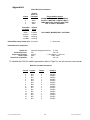
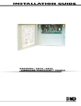
Appendix A
FA416 Receiver Parameters
Output
1
2
3
4
Default
Active on
Condition
Alarm
Alarm
Alarm
Alarm
Transmitter
Condition
Default
Mode
Alarm
Inactive
Tamper
Low Batt
Follower
Follower
Latching
Latching
Programmable Options
ALARM / ALARM+TAMPER / TAMPER /
LO BATT / INACTIVE / TAMP+LO BATT /
TAMP+INACTIVE / LO BATT+INACTIVE /
ANY TX FAULT / DISABLED
FOLLOWER / MOMENTARY / LATCHING
Default Momentary Output time: 4 seconds
1 - 16 seconds
Default Receiver Parameters:
System ID:
Point supervision:
Supervision window:
Access code:
Vision Plus compatible:
(randomly assigned at factory)
0 - 255
Yes
Yes / No
4 hours
1 - 99 minutes, 1 - 99 hours
3446
0000 - 9999
No
Yes / No
To initialize the FA416 to default parameters refer to Page 3 or see the receiver user manual.
Default Transmitter Parameters
Point # Contact
1
N/O
2
N/O
3
N/C
4
N/C
5
N/O
6
N/O
7
N/O
8
N/O
9
N/C
10
N/C
11
N/C
12
N/C
13
N/C
14
N/C
15
N/C
16
N/C
© 1997 INOVONICS Corporation
Output
1
2
3
4
1
2
3
4
1
2
3
4
1
2
3
4
Check-in
60 SEC
60 SEC
60 SEC
60 SEC
60 SEC
60 SEC
60 SEC
60 SEC
60 SEC
60 SEC
60 SEC
60 SEC
60 SEC
60 SEC
60 SEC
60 SEC
12
LIT-FA116-USER 01860
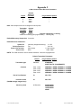
Appendix B
FA464 Receiver Parameters
Output
1
2
3
4
...
...
16
Default
Active on
Condition
Alarm
Alarm
Alarm
Alarm
Programmable Options
ALARM / ALARM+TAMPER / TAMPER /
LO BATT / INACTIVE / TAMP+LO BATT /
TAMP+INACTIVE / LO BATT+INACTIVE /
ANY TX FAULT / DISABLED
Alarm
Transmitter
Condition
Default
Mode
Alarm
Inactive
Tamper
Low Batt
Follower
Follower
Latching
Latching
FOLLOWER / MOMENTARY / LATCHING
Default Momentary Output time: 4 seconds
1 - 16 seconds
Default Receiver Parameters:
System ID:
Point supervision:
Supervision window:
Access code:
Vision Plus compatible:
(randomly assigned at factory)
0 - 255
Yes
Yes / No
4 hours
1 - 99 minutes, 1 - 99 hours
3446
0000 - 9999
No
Yes / No
To initialize the FA464 to default parameters refer to Page 3 or see the receiver user manual.
© 1997 INOVONICS Corporation
13
LIT-FA116-USER 01860
Default FA464 Transmitter Parameters
Point# Contact Output
1
N/O
1
2
N/O
2
3
N/C
3
4
N/C
4
5
N/O
1
6
N/O
2
7
N/O
3
8
N/O
4
9
N/C
1
10
N/C
2
11
N/C
3
12
N/C
4
13
N/C
1
14
N/C
2
15
N/C
3
16
N/C
4
17
N/C
5
18
N/C
5
19
N/C
5
20
N/C
5
21
N/C
6
22
N/C
6
23
N/C
6
24
N/C
6
25
N/C
7
26
N/C
7
27
N/C
7
28
N/C
7
29
N/C
8
30
N/C
8
31
N/C
8
32
N/C
8
Check-In
60 SEC
60 SEC
60 SEC
60 SEC
60 SEC
60 SEC
60 SEC
60 SEC
60 SEC
60 SEC
60 SEC
60 SEC
60 SEC
60 SEC
60 SEC
60 SEC
60 SEC
60 SEC
60 SEC
60 SEC
60 SEC
60 SEC
60 SEC
60 SEC
60 SEC
60 SEC
60 SEC
60 SEC
60 SEC
60 SEC
60 SEC
60 SEC
Point#
33
34
35
36
37
38
39
40
41
42
43
44
45
46
47
48
49*
50
51
52
53
54
55
56
57
58
59
60
**
61
62
63
64
Contact Output
N/C
9
N/C
9
N/C
9
N/C
9
N/C
10
N/C
10
N/C
10
N/O
10
N/O
11
N/O
11
N/O
11
N/O
11
N/O
12
N/O
12
N/O
12
N/O
12
N/O
13
N/O
13
N/O
13
N/O
13
N/O
14
N/O
14
N/O
14
N/O
14
N/O
15
N/O
15
N/O
15
N/O
15
N/O+INT
16
N/O+INT
16
N/O+INT
16
N/O+INT
16
Check-In
60 SEC
60 SEC
60 SEC
60 SEC
60 SEC
60 SEC
60 SEC
60 SEC
60 SEC
60 SEC
60 SEC
60 SEC
60 SEC
60 SEC
60 SEC
60 SEC
5 MIN
5 MIN
5 MIN
5 MIN
5 MIN
5 MIN
5 MIN
5 MIN
5 MIN
5 MIN
5 MIN
5 MIN
60 SEC
60 SEC
60 SEC
60 SEC
*Note: Points 49-60 are programmed to check in every five minutes.This will extend battery life slightly depending on
which transmitter is used.
**Note: Points 61 through 64: Normally Open plus Internal Contact = Yes.
© 1997 INOVONICS Corporation
14
LIT-FA116-USER 01860
Appendix C
C404 4-channel Slave Receiver Parameters
Output
1
2
3
4
Default
Active on
Condition
Alarm
Alarm
Alarm
Alarm
Programmable Options
Not programmable
"
"
"
Note: C404 outputs cannot be re-assigned to other points.
Transmitter
Condition
Default
Mode
Follower / Momentary / Latching
Alarm
Follower
Global Fault Latching (Not programmable) Latching only
Default Momentary Output time: 2 seconds
Default Receiver Parameters:
System ID:
Point supervision:
Supervision window:
Access code:
(randomly assigned at factory)
0 - 255
Yes
Yes / No
240 minutes
0 - 240 minutes
0000
0000 - 9999
NOTE: The C404 cannot be reset to default conditions. It must be reprogrammed.
Default Transmitter Parameters
Default
Transmitter type
Programmable Options
Standard
STANDARD
4-BUTTON TX (C100 REMOTE)
Point 1: N/O
Point 2: N/O
Point 3: N/C
Point 4: N/C
NORMALLY OPEN / NORMALLY CLOSED
NORMALLY OPEN / NORMALLY CLOSED
NORMALLY OPEN / NORMALLY CLOSED
NORMALLY OPEN / NORMALLY CLOSED
End of Line Resistor
No
NO / YES
Internal Contact
(C200W widegap magnet loop)
No
NO / YES
60 Seconds
60 SECONDS
30 SECONDS
10 SECONDS
NONE
Contacts
Check-In period
© 1997 INOVONICS Corporation
15
LIT-FA116-USER 01860
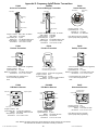
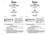
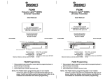
Appendix D: Frequency Agile
Series Transmitters
FA200
Universal Transmitter
FA202
Smoke Detector
FA200W
Universal Widegap Transmitter
Reset button
Programming
header
Programming
header
B a t t e ry
B a tte r y
Tamper switch
Widegap
reed switch
Tamper switch
Battery terminals
Program contacts:
EOL resistor:
Typical battery life:
Battery type:
Switch trigger:
Dimensions:
N/O or N/C, as needed
as needed
3 years
4.5V alkaline battery pack
1.5 seconds, minimum
1.25" x 6.00" x 0.750"
FA203
Pendant Transmitter
Programming
Header
Reset Button
Reset button
Battery terminals
Program contacts:
EOL resistor:
Internal contact:
Typical battery life:
Battery type:
Switch trigger:
Dimensions:
N/O or N/C, as needed
as needed
as needed
3 years
4.5V alkaline battery pack
1.5 seconds, minimum
1.25" x 6.00" x 0.750"
Program contacts:
Typical battery life:
Batteries (2):
Dimensions:
N/C
1 year
3V lithium
6.0" Diameter
Note: Remove jumper to program,
replace jumper after programming.
FA204
Pendant Transmitter
FA205
Beltclip Transmitter
Reset button
Reset button
Programming header
3.0V
Check-in interval:
Program contacts:
Typical battery life:
Battery (or equivalent):
Dimensions:
Programming header
+ 3.0V
+
60 seconds* (suggested)
N/O
3-5 years
3.0V lithium Sanyo CR2
3.10" x 1.62" x 0.750"
* To extend battery life, actual check-in
is 2 to 3 times the programmed
value.
FA206
PIR Motion Detector
Reset button
Programming header
3.0V
Programming
header
Reset button
Note: Remove battery cover to access
Reset Button and Programming Head
Check-in interval:
Program contacts:
Typical battery life:
Battery
Dimensions:
60 seconds* (suggested)
N/O
2 years
3.0V Sanyo LiMn CR14250
2.8" x 1.7" x 0.83"
Check-in interval:
Program contacts:
Typical battery life:
Battery (or equivalent):
Dimensions:
+
60 seconds* (suggested)
N/O
3-5 years
3.0V lithium Sanyo CR2
3.10" x 1.62" x 0.750"
* To extend battery life, actual check-in
is 2 to 3 times the programmed
value.
FA206DS
PIR Motion Detector
FA207
Glassbreak Detector
Programming header
(with tamper shunt)
Programming
header
Reset button
Battery
3.0V
Reset button
+
+ 3.6V
1-zone or 2-zone
detection header
+
3.0V
Tamper switch
Sensitivity selector
Walk test LED
Tamper switch
Mirror Optics
Optional battery
Program contacts:
Typical battery life:
Battery:
Sleep after trip:
Dimensions:
N/C
2 years (with 2 batteries)
3.6V lithium Tadiran TL2150
90 seconds
3.75" x 2.88" x 2.40"
Program contacts:
Typical battery life:
Battery:
Sleep after trip:
Dimensions:
N/C
2 years
3.0V lithium DL123A
180 seconds
3.75" x 5.75" x 2.50"
Program contacts:
Typical battery life:
Battery:
Dimensions:
N/O
2 years
3.0V lithium DL123A
4.25" x 3.12" x 1.63"
Note: Remove jumper to program.
replace jumper after programming.
Note: Batteries are always supervised. Lithium batteries are capacity-tested at 18-hour intervals.
The transmitter will deactivate 2 weeks after low battery is detected.
© 1997 INOVONICS Corporation
16
LIT-FA116-USER 01860
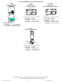
Series Transmitters (Continued)
Frequency Agile
FA209
Billtrap Transmitter
FA210
Reduced-size
Universal Transmitter
FA210W
Reduced-size
Universal Widegap Transmitter
Programming header
Reset button
+
+
Delay selector
3.0V
3.0V
Reed switch
indicator
FA210W Widegap
Reed switches
Tamper switch
3V LITHIUM
3V LITHIUM
Tamper switch
Reset button
Programming header
Program contacts:
EOL, internal contacts:
Typical battery life:
Battery type (Qty. 2):
Dimensions:
N/O
No
1-2 years @ 60s check-in
3.0V lithium CR2450N
2.63" x 6.19" x 0.750"
Program contacts:
EOL resistor:
Typical battery life:
Battery type:
Switch trigger:
Dimensions:
N/O or N/C, as needed
as needed
4 years
3.0V lithium DL123A
1.5 seconds, minimum
3.55" x 1.70" x 0.920"
Program contacts:
EOL resistor:
Internal contact:
Typical battery life:
Battery type:
Switch trigger:
Dimensions:
N/O or N/C, as needed
as needed
as needed
4 years
3.0V lithium DL123A
1.5 seconds, minimum
3.55" x 1.70" x 0.920"
Tamper Switch
Reset Button
3.0V
+
FA250
High Power Transmitter
Programming Header
External contact
Terminals
Program contacts:
EOL resistor:
Typical battery life:
Battery type:
Switch trigger:
Dimensions:
N/O or N/C, as needed
as needed
1-2 years
3.0V lithium DL123A
1.5 seconds, minimum
1.25" x 6.00" x 0.750"
Note: Batteries are always supervised. Lithium batteries are capacity-tested at 18-hour intervals.
The transmitter will deactivate 2 weeks after low battery is detected.
© 1997 INOVONICS Corporation
17
LIT-FA116-USER 01860
Appendix E
Warranty & Disclaimer
Inovonics Corporation ("Inovonics") warrants its products ("Product" or "Products") to conform to its own
specifications and to be free of defects in materials and workmanship under normal use for a period of twenty-four
(24) months from the date of manufacture. Within the warranty period Inovonics Corporation will repair or replace,
at its option, all or any part of the warrantied product. Inovonics will not be responsible for dismantling and/or
reinstallation charges. To exercise the warranty, the User ("User", "Installer" or "Consumer") must be given a
Return Material Authorization ("RMA") Number by Inovonics. Details of shipment will be arranged at that time.
This warranty does not apply in cases of improper installation, misuse, failure to follow installation and operating
instructions, alteration, abuse, accident or tampering, and repair by anyone other than Inovonics.
This warranty is exclusive and expressly in lieu of all other warranties, obligations or liabilities, whether written, oral,
express, or implied, including any warranty of merchantability or fitness for a particular purpose. Inovonics will not
be liable to anyone for any consequential or incidental damages for breach of this warranty or any other warranties.
This warranty will not be modified, varied or extended. Inovonics does not authorize any person to act on its behalf
to modify, vary or extend this warranty. This warranty will apply to Inovonics Products only. All other products,
accessories or attachments used in conjunction with Inovonics equipment, including batteries, will be covered
solely by their own warranty, if any. Inovonics will not be liable for any direct, incidental or consequential damage or
loss whatsoever, caused by the malfunction of Product due to products, accessories, or attachments of other
manufacturers, including batteries, used in conjunction with Inovonics Products.
This warranty does not warrant the replacement of batteries that are used to power Inovonics Products.
The User recognizes that a properly installed and maintained security system may only reduce the risk of events
such as burglary, robbery, personal injury and fire. It does not insure or guarantee that there will be no death,
personal damage and/or damage to property as a result. Inovonics does not claim that the Product may not be
compromised and/or circumvented, or that the Product will prevent any death, personal and/or bodily injury
and/or damage to property resulting from burglary, robbery, fire or otherwise, or that the Product will in all
cases provide adequate warning or protection.
Inovonics Corporation shall have no liability for any death, injury or damage, however incurred, based on a
claim that Inovonics Products failed to function. However, if Inovonics is held liable, directly or indirectly, for any
loss or damage arising under this limited warranty or otherwise, regardless of cause or origin, Inovonics' maximum
liability will not in any case exceed the purchase price of the Product, which will be fixed as liquidated damages and
not as a penalty, and will be the complete and exclusive remedy against Inovonics.
!
!
Warning: The User should follow all installation, operation and maintenance instructions. The User is
strongly advised to conduct Product and systems tests at least once each week. Changes in environmental
conditions, electric or electronic disruptions and tampering, may cause the Product to not perform as expected.
Warning: Inovonics warrants its Product to the User. The User is responsible for exercising all due prudence
and taking necessary precautions for the safety and protection of lives and property wherever Inovonics Products are
installed. Inovonics strongly advises the User to program Products to be supervised whenever used in applications
affecting life safety. Users are warned that unsupervised devices are subject to undetected failure due to malfunction,
battery failure, tampering, or changes in environment.
© 1997 INOVONICS Corporation
18
LIT-FA116-USER 01860
Frequency Agile® Receivers
compatible with the FA116 Executive Programmer
FA416
FA416D
FA426
FA464DR
16-channel / 4-output
16-channel / 4-output with display
DMP XR20 16-channel receiver
64-channel / 16-output
Inovonics C-series Receivers
C404
4-channel slave receiver
Inovonics Wireless Corporation
315 CTC Blvd
Louisville CO 80027
(800) 782-2709
FAX: (303) 939-8970
E-MAIL: [email protected]
www.inovonics.com
© 1997 INOVONICS Corporation
19
LIT-FA116-USER 01860