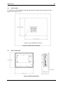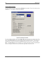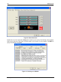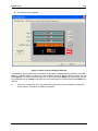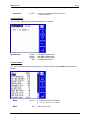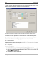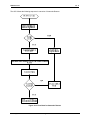
1
User Manual for HE–RX371 / HERX371C101 MAN0924-01-EN MAN0924-01-EN PREFACE PREFACE This manual explains how to use the RX-371 OCS Modules. Copyright (C) 2009 Horner APG, LLC, 59 South State Avenue, Indianapolis, Indiana 46201. All rights reserved. No part of this publication may be reproduced, transmitted, transcribed, stored in a retrieval system, or translated into any language or computer language, in any form by any means, electronic, mechanical, magnetic, optical, chemical, manual or otherwise, without the prior agreement and written permission of Horner APG, Inc. All software described in this document or media is also copyrighted material subject to the terms and conditions of the Horner Software License Agreement. Information in this document is subject to change without notice and does not represent a commitment on the part of Horner APG. Cscape, SmartStack, SmartStix and CsCAN are trademarks of Horner APG. Ethernet is a trademark of Xerox Corporation. Micro SD and CompactFlash are registered trademarks of Sandisk Corporation. For user manual updates, contact Technical Support: North America: Tel: (+) (317) 916-4274 Fax: (+) (317) 639-4279 Web: www.heapg.com Email: [email protected] Europe: Tel: (+) 353-21-4321-266 Fax: (+) 353-21-4321-826 Web: www.horner-apg.com Email: [email protected] February 8, 2010 Page 3 of 124 # 1018 MAN0924-01-EN PREFACE LIMITED WARRANTY AND LIMITATION OF LIABILITY Horner APG, LLC, ("HE-APG") warrants to the original purchaser that the RX-371 OCS module manufactured by HE-APG is free from defects in material and workmanship under normal use and service. The obligation of HE-APG under this warranty shall be limited to the repair or exchange of any part or parts which may prove defective under normal use and service within two (2) years from the date of manufacture or eighteen (18) months from the date of installation by the original purchaser whichever occurs first, such defect to be disclosed to the satisfaction of HE-APG after examination by HE-APG of the allegedly defective part or parts. THIS WARRANTY IS EXPRESSLY IN LIEU OF ALL OTHER WARRANTIES EXPRESSED OR IMPLIED INCLUDING THE WARRANTIES OF MERCHANTABILITY AND FITNESS FOR USE AND OF ALL OTHER OBLIGATIONS OR LIABILITIES AND HE-APG NEITHER ASSUMES, NOR AUTHORIZES ANY OTHER PERSON TO ASSUME FOR HE-APG, ANY OTHER LIABILITY IN CONNECTION WITH THE SALE OF THIS RX-371 OCS module. THIS WARRANTY SHALL NOT APPLY TO THIS RX-371 OCS module OR ANY PART THEREOF WHICH HAS BEEN SUBJECT TO ACCIDENT, NEGLIGENCE, ALTERATION, ABUSE, OR MISUSE. HE-APG MAKES NO WARRANTY WHATSOEVER IN RESPECT TO ACCESSORIES OR PARTS NOT SUPPLIED BY HE-APG. THE TERM "ORIGINAL PURCHASER", AS USED IN THIS WARRANTY, SHALL BE DEEMED TO MEAN THAT PERSON FOR WHOM THE RX-371 OCS MODULE IS ORIGINALLY INSTALLED. THIS WARRANTY SHALL APPLY ONLY WITHIN THE BOUNDARIES OF THE CONTINENTAL UNITED STATES. In no event, whether as a result of breach of contract, warranty, tort (including negligence) or otherwise, shall HEAPG or its suppliers be liable of any special, consequential, incidental or penal damages including, but not limited to, loss of profit or revenues, loss of use of the products or any associated equipment, damage to associated equipment, cost of capital, cost of substitute products, facilities, services or replacement power, down time costs, or claims of original purchaser's customers for such damages. To obtain warranty service, return the product to your distributor with a description of the problem, proof of purchase, post paid, insured and in a suitable package. ABOUT PROGRAMMING EXAMPLES Any example programs and program segments in this manual or provided on accompanying diskettes are included solely for illustrative purposes. Due to the many variables and requirements associated with any particular installation, Horner APG cannot assume responsibility or liability for actual use based on the examples and diagrams. It is the sole responsibility of the system designer utilizing the RX-371 OCS module to appropriately design the end system, to appropriately integrate the RX-371 OCS module and to make safety provisions for the end equipment as is usual and customary in industrial applications as defined in any codes or standards which apply. Note: The programming examples shown in this manual are for illustrative purpose only. Proper machine operation is the sole responsibility of the system integrator. February 8, 2010 Page 4 of 124 # 1018 MAN0924-01-EN PREFACE Table of Contents PREFACE.................................................................................................................................................. 3 For user manual updates, contact Technical Support:.............................................................................. 3 LIMITED WARRANTY AND LIMITATION OF LIABILITY ......................................................................... 4 ABOUT PROGRAMMING EXAMPLES..................................................................................................... 4 VISUAL MAP OF MAJOR TASKS AND THE KEY CHAPTERS TO ASSIST YOU ................................... 8 CHAPTER 1 : SAFETY / COMPLIANCE .................................................................................................... 9 1.1 Safety Warnings and Guidelines ................................................................................................... 9 1.2 Grounding .................................................................................................................................... 10 1.3 CE Compliance............................................................................................................................ 10 CHAPTER 2 : INTRODUCTION ................................................................................................................ 11 2.1 Visual Overview ........................................................................................................................... 11 2.2 Connectivity to the RX-371.......................................................................................................... 13 2.3 Detailed Product Descriptions ..................................................................................................... 13 2.4 Product Specifications ................................................................................................................. 15 2.5 Required and Suggested Accessories ........................................................................................15 2.6 Useful Documents and References............................................................................................. 16 CHAPTER 3 : MECHANICAL INSTALLATION........................................................................................ 17 3.1 Overview...................................................................................................................................... 17 3.2 Mounting Requirements .............................................................................................................. 17 3.3. Mounting Orientation ................................................................................................................... 18 3.4 Panel Cut-Out .............................................................................................................................. 19 3.5 RX-371 Dimensions..................................................................................................................... 19 3.6 Factors Affecting Panel Layout Design and Clearances............................................................. 20 3.7 Panel Layout Design and Clearance Checklist ........................................................................... 21 CHAPTER 4 : ELECTRICAL INSTALLATION ......................................................................................... 23 4.1 Initial Electrical Installation .......................................................................................................... 23 4.2 Grounding Definition.................................................................................................................... 23 4.3 Ground Specifications ................................................................................................................. 23 4.4 How to Test for Good Ground ..................................................................................................... 23 4.5 RX-371 Primary Power Port ........................................................................................................ 24 CHAPTER 5 : SERIAL COMMUNICATIONS ........................................................................................... 25 5.1 Overview...................................................................................................................................... 25 5.2 Port Descriptions ......................................................................................................................... 25 5.3 Wiring........................................................................................................................................... 25 5.4 RS-485 Termination .................................................................................................................... 27 5.5 RS-485 Biasing............................................................................................................................ 27 5.6 Cscape Programming via Serial Port .......................................................................................... 27 5.7 Ladder-Controlled Serial Communication ................................................................................... 27 5.8 Downloadable Serial Communication Protocols ......................................................................... 28 CHAPTER 6: CAN COMMUNICATIONS................................................................................................. 29 6.1 Overview...................................................................................................................................... 29 6.2 Port Description ........................................................................................................................... 29 6.3 CAN (NET1) Port Wiring.............................................................................................................. 29 6.4 Cscape Programming via CAN.................................................................................................... 30 6.5 Ladder-Controlled CAN Communication ..................................................................................... 30 6.6 Using CAN for I/O Expansion (Network I/O) ............................................................................... 30 CHAPTER 7: ETHERNET COMMUNICATION......................................................................................... 31 7.1 Ethernet Module Protocols and Features.................................................................................... 31 7.2 Ethernet System Requirements................................................................................................... 31 7.3 Ethernet Module Specifications ................................................................................................... 31 February 8, 2010 Page 5 of 124 # 1018 MAN0924-01-EN PREFACE 7.4 Ethernet Module Configuration.................................................................................................... 31 CHAPTER 8: REMOVABLE MEDIA......................................................................................................... 37 8.1 Micro SD Overview...................................................................................................................... 37 8.1.1 Accessing Files with an RX-371 OCS................................................................................ 37 8.1.2 Accessing Files with a PC .................................................................................................. 37 8.2 Removable Media (RM) Function Blocks in Cscape ................................................................... 37 8.3 Configuring Removable Media Manager graphic object in Cscape ............................................ 38 8.4 Filenames used with the Removable Media (RM) Function Blocks ............................................ 38 8.5 System Registers used with RM.................................................................................................. 38 CHAPTER 9: SMARTSTACK I/O ............................................................................................................. 39 9.1 Configuration Procedures............................................................................................................ 39 CHAPTER 10: SYSTEM SETTINGS AND ADJUSTMENTS.................................................................... 45 10.1 System Menu - Overview ............................................................................................................ 45 10.2 System Menu – Navigation and Editing ...................................................................................... 46 10.3 System Menu – Details................................................................................................................ 46 10.4 Touch screen calibration ............................................................................................................. 58 CHAPTER 11: USER INTERFACE............................................................................................................ 61 11.1 Overview...................................................................................................................................... 61 11.2 Displaying and entering Data ...................................................................................................... 61 11.3 Alpha-numeric keypad................................................................................................................. 62 11.4 Screen Navigation ....................................................................................................................... 64 11.5 Ladder Based Screen Navigation................................................................................................ 65 11.6 Beeper Acknowledgement........................................................................................................... 65 11.7 Touch (Slip) Sensitivity ................................................................................................................ 66 11.8 Alarms.......................................................................................................................................... 66 11.9 Removable Media........................................................................................................................ 67 11.10 OK and Run Status...................................................................................................................... 69 11.11 Screen Saver ............................................................................................................................... 70 11.12 Screen Brightness ....................................................................................................................... 70 CHAPTER 12: REGISTERS....................................................................................................................... 71 12.1 RX-371 Resources ...................................................................................................................... 71 12.1.1 Overview...............................................................................................................................71 12.1.2 Resource Limits .................................................................................................................. 71 12.1.3 Resource Definitions .......................................................................................................... 72 CHAPTER 13: CSCAPE CONFIGURATION ............................................................................................ 77 13.1 Overview...................................................................................................................................... 77 13.2 Cscape Status Bar....................................................................................................................... 77 13.3 Establishing Communications ..................................................................................................... 78 13.4 Models supported ........................................................................................................................ 86 13.5 Configuration ............................................................................................................................... 86 CHAPTER 14: FAIL–SAFE SYSTEM ........................................................................................................ 89 14.1 Overview...................................................................................................................................... 89 14.2 Settings........................................................................................................................................ 89 14.3 Backup / Restore Data ................................................................................................................ 90 14.4 AutoLoad ..................................................................................................................................... 94 14.5 AutoRun....................................................................................................................................... 96 CHAPTER 15: CLONE UNIT..................................................................................................................... 97 15.1 Overview...................................................................................................................................... 97 15.2 Clone ........................................................................................................................................... 97 15.3 Load Clone .................................................................................................................................. 99 CHAPTER 16: SMTP (EMAIL) PROTOCOL ........................................................................................... 101 16.1 Overview.................................................................................................................................... 101 16.2 Configuration ............................................................................................................................. 101 16.2.1 Email Configuration ................................................................................................................... 101 February 8, 2010 Page 6 of 124 # 1018 MAN0924-01-EN PREFACE 16.2.2 Email Target Directory Settings................................................................................................. 105 16.2.3 Outgoing Emails Settings (SEND): (Emails sent from the controller to Groups) ...................... 108 16.2.4 Email Status............................................................................................................................... 111 CHAPTER 17: MAINTENANCE.............................................................................................................. 113 17.1 Firmware Updates ..................................................................................................................... 113 17.2 Backup Battery .......................................................................................................................... 113 CHAPTER 18: TROUBLESHOOTING / TECHNICAL SUPPORT .......................................................... 117 18.1 Connecting to the RX-371 ......................................................................................................... 117 18.1.1 Connecting Troubleshooting Checklist (Serial Port – MJ1/MJ2 Programming)......... 118 18.1.2 Connecting Troubleshooting Checklist (USB Port - Mini B Programming) ................ 118 18.1.3 Connecting Troubleshooting Checklist (Ethernet port Programming) ....................... 118 18.2 Local Controller and Local I/O ................................................................................................... 118 18.2.1 Local I/O Troubleshooting Checklist...............................................................................119 18.3 CsCAN Network ........................................................................................................................ 119 18.3.1 CsCAN Network Troubleshooting Checklist .................................................................. 119 18.4 Removable Media...................................................................................................................... 120 18.5 Technical Support Contacts ...................................................................................................... 120 INDEX ....................................................................................................................................................... 121 TABLE OF FIGURES ............................................................................................................................... 123 February 8, 2010 Page 7 of 124 # 1018 MAN0924-01-EN PREFACE VISUAL MAP OF MAJOR TASKS AND THE KEY CHAPTERS TO ASSIST YOU The following map is provided to show you the major types of tasks needed to be performed and the key chapters in this manual you need to refer to for information and help. Directions: Major tasks are listed at the top of the map with the key chapters listed beneath that you need to consult in order to perform the tasks. FIRST STEP of ANY TASK: DATASHEET Each RX-371 unit is sent with a datasheet in the box. The datasheet is the first document you need to refer to for model-specific information related to RX-371 models such as pin-outs, jumper settings, and other key installation information. Visit our website (http://www.heapg.com/) to obtain updates to datasheets, manuals and user documentation. QUICK START INSTALLATION PROGRAMMING TROUBLESHOOTING Safety / Compliance page 9 Introduction page 11 Safety / Compliance page 9 Introduction page 11 Mechanical Installation page 17 Electrical Installation page 23 Safety / Compliance page 9 Introduction page 11 Serial Communication Page 25 CAN Communications page 29 Ethernet Communication Page 31 Removable Media page 35 System Settings page 43 User Interface page 59 Registers page 69 Cscape Configuration page 75 Fail- Safe System Page 87 Clone Unit Page 95 Email Page 99 Safety / Compliance page 9 Introduction page 11 Maintenance page 111 Troubleshooting page 113 February 8, 2010 Page 8 of 124 # 1018 MAN0924-01-EN CH.1 CHAPTER 1: SAFETY / COMPLIANCE 1.1 Safety Warnings and Guidelines When found on the product, the following symbols specify: Warning: Consult user documentation. Warning: Electrical Shock Hazard. WARNING: EXPLOSION HAZARD: Do not disconnect equipment unless power has been switched off or the area is known to be non-hazardous WARNING: To avoid the risk of electric shock or burns, always connect the safety (or earth) ground before making any other connections. WARNING: To reduce the risk of fire, electrical shock, or physical injury it is strongly recommended to fuse the voltage measurement inputs. Be sure to locate fuses as close to the source as possible. WARNING: Replace fuse with the same type and rating to provide protection against risk of fire and shock hazards. WARNING: In the event of repeated failure, do not replace the fuse again as a repeated failure indicates a defective condition that will not clear by replacing the fuse. WARNING: EXPLOSION HAZARD: Substitution of components may impair suitability for Class I, Division 2 WARNING: The USB parts are for operational maintenance only. Do not leave permanently connected unless area is known to be non-hazardous WARNING: EXPLOSION HAZARD: BATTERIES MUST ONLY BE CHANGED IN AN AREA KNOWN TO BE NON-HAZARDOUS WARNING: Battery May Explode If Mistreated. Do Not Recharge, Disassemble or Dispose Of In Fire WARNING: Only qualified electrical personnel familiar with the construction and operation of this equipment and the hazards involved should install, adjust, operate, or service this equipment. Read and understand this manual and other applicable manuals in their entirety before proceeding. Failure to observe this precaution could result in severe bodily injury or loss of life. • • All applicable codes and standards need to be followed in the installation of this product. For I/O wiring (discrete), use the following wire type or equivalent: Belden 9918, 18 AWG or larger. Adhere to the following safety precautions whenever any type of connection is made to the module. • • • • • • 2/8/2010 Connect the green safety (earth) ground first before making any other connections. When connecting to electric circuits or pulse-initiating equipment, open their related breakers. Do not make connections to live power lines. Make connections to the module first; then connect to the circuit to be monitored. Route power wires in a safe manner in accordance with good practice and local codes. Wear proper personal protective equipment including safety glasses and insulated gloves when making connections to power circuits. Ensure hands, shoes, and floors are dry before making any connection to a power line. Page 9 of 124 # 1018 CH.1 • • 1.2 MAN0924-01-EN Make sure the unit is turned OFF before making connection to terminals. Make sure all circuits are de-energized before making connections. Before each use, inspect all cables for breaks or cracks in the insulation. Replace immediately if defective. Grounding Grounding is covered in various chapters within this manual. • • 1.3 For grounding specifications and testing for a good ground, refer to section 4.2 For Panel grounding, refer to section 4.3 CE Compliance To check for compliance and updates, visit our website at: http://www.heapg.com/Pages/TechSupport/ProductCert.html February 8, 2010 Page 10 of 124 # 1018 MAN0924-01-EN CH.2 CHAPTER 2: INTRODUCTION 2.1 Visual Overview The RX-371 OCS provides flexible options allowing you to choose the functionality you need. User Interface Front View Smart Stack Connector Back View February 8, 2010 Page 11 of 124 # 1018 CH. 2 MAN0924-01-EN Removable Media USB B Right Side Ethernet USB A Bottom Side DIP Switches Power CAN MJ2 MJ1 Left Side Figure 2.1: Visual Overview of RX-371 RX Model RX-371 Network On-Board Ethernet 100BaseT Screen Type 5.7"QVGA TFT LCD with LED backlight Standard RX Features Micro SD 2 Serial Ports Ethernet USB A & USB B Metal SmartStack Provide a wide variety of I/O options. Requires little space and are easy to install. SmartStix Modules It is a family of remote I/O products. February 8, 2010 Page 12 of 124 # 1018 MAN0924-01-EN 2.1.1 CH.2 Where to Find Information about the RX-371 a. Datasheets - Refer datasheet for information related to specific model, RX371 is shipped with MAN0925. b. User Manual - This manual provides general information of RX-371 models. Visit our website (http://www.heapg.com/) to obtain user documentation and updates. Four main types of information are covered in the manual. Safety and Installation guidelines / instructions (Mechanical and Electrical) Descriptions of features Configuration and Use Maintenance and Support 2.2 Connectivity to the RX-371 The RX-371 has tremendous capabilities for connecting to a variety of devices. The diagram below shows some examples of devices that can be used with the RX-371 Other OCS Devices Drives Other OCS Devices PLCs Smart Stix I/O CAN Serial Bar Code Readers OPC Server Printers Cscape SCADA OPC Servers RX-371 Serial I/O Sensors Indicators Alarms Encoders Pumps Relays Solenoids Ethernet Smart Stack I/O USB OPC Server Modbus TCP Devices (CsCAN) Cscape. Cscape Flash drive Figure 2.2: Visual Overview of Types of Devices that can be connected to RX-371 2.3 Detailed Product Descriptions a. Features The RX-371 combines several desirable functions in one compact package. Each unit is a highly integrated operator interface and controller with expandable I/O and networking capabilities have standard features consisting of the following: • • • • • • Metal enclosure with aluminium front and steel back cover. Bright, 32000 Color graphical Touch sensing LCD display Domed keypad with magnetic contact. Plastic touch screen that is thicker and more damage resistant. Display of complex graphical objects including trends, gauges, meters and animations. CsCAN Networking port February 8, 2010 Page 13 of 124 # 1018 CH. 2 • • • • • • • • • • b. MAN0924-01-EN RS-232 / RS-485 Serial Ports Configurable serial protocols for communication to drives, PLC’s, or other serial peripherals. Advanced control capabilities including floating point, multiple auto tuning PID loops and string handling capabilities. Removable Media for up to two gigabytes of storage of programs, data logging or screen captures. System Key and Configurable Function Keys USB networking port for communication with PC’s and programming of controller. USB supporting flash drive. Ethernet (10/100 Mbps) Smart Stack I/O Expansion and Smart Stix remote I/O. Cscape programming software allowing all aspects of RX-371 to be programmed and configured from one integrated application. CsCAN Network The RX-371 has the CsCAN networking port for communication with remote I/O, other controllers or PC’s. (CsCAN is pronounced “see-scan”). CAN-based network hardware is used in the controllers because of CAN’s automatic error detection, ease of configuration, low-cost of design and implementation and ability to operate in harsh environments. Networking abilities are built-in to the RX-371 and require no external or additional modules. Figure 2.3: Pass through Function (Available in CsCAN Networks Only) The RX-371 features the ability to pass through programming commands. When attached to a RX-371 serial port, a programming package (i.e., Cscape) can access other RX units or any other OCS unit connected to a CsCAN network by passing the programming command through the serial port to the network port. One Cscape package (connected to one RX unit) can program all RX or other OCS units on the CsCAN network. When several RX models are networked together to achieve a specific purpose, the system acts like a large parallel-processing controller. c. Cscape Software RX-371 hardware is programmed with a Windows-based PC application called Cscape (HE500OSW232). Cscape (pronounced “see-scape”) stands for Control Station Central Application Programming Environment. Provided there is one serial connection to one node on the network (i.e., CsCAN Network), the operator has control over the entire system. The operator can upload, download, monitor and debug to any node on the network. This application can be used to program, configure, monitor and debug all aspects of the RX-371 unit. It is used for programming RX-371 OCS ladder logic, programming user displays for the RX-371 OCS, configuring the network for global digital and analog data, setting system-wide security and monitoring controllers in the system. February 8, 2010 Page 14 of 124 # 1018 MAN0924-01-EN 2.4 CH.2 Product Specifications Table 1 - RX371 Specifications Display Type (LCD with Backlight) Display Size Display Screen Dimensions Display Memory Display Life User Keys Screens supported Colors Primary power Steady state current Inrush current 5.7” QVGA TFT 5.7” 320 x 240 2.75MB Minimum 40000 hours (50% brightness, 25 deg C) 5 user-defined Function keys and a System key 1023 32768 10 – 30 VDC 0.8A @ 24 VDC, 2 A @ 10 VDC 30 A for 1 ms @ 24 VDC – DC Switched 2.5 A for 4 ms @ 24 VDC - AC Switched Product Descriptions Height Width Depth Serial Ports Terminal Type Weight Portable Memory Temperature & Humidity Clock Accuracy Compliance 2.5 5.964” (151.49mm) 7.682” (195.12mm) 3.223” (81.86mm) RS232 & RS485. Software Selectable Screw Type, 5mm removable 54 oz (1.53kg) Micro SD card slot -30°C to +60°C & 5 to 95% Non-condensing +/- 35 ppm maximum at 25° C (+/- 1.53 Minutes per Month) USA:http://www.heapg.com/Pages/TechSupport/ProductCert.html EUROPE: http://www.horner-pg.com/en/support/certification.aspx Required and Suggested Accessories The following table contains a list of required and suggested RX-371 accessories. Visit our website (http://www.heapg.com/) to view updates on new products and accessories. Note: The RX-371 is not shipped with a programming cable in the box. To obtain a programming cable, order HE500CBL300. Table 2.1 – RX-371 Accessories Part Number HE500OSW232 HE500CBL300 HEUSB600 Part Number HE-MC1 Description Cscape Software Package. Includes Cscape CD, 9-pin OCS Programming Cable, RJ-45 Programming Cable, Documentation OCS Programming Cable, 9-pin female (PC) to RJ-45 (OCS) - 6 feet. USB programming kit. Includes USB to RS-232 adapter, and 6-foot RS-232 cable with D-sub connections. Requires HE500CBL300 to program the RX-371 Description Removable Media card - compatible with RX-371. HE-MR1 Media Card Reader for HE-MC1. Portable device allows HE-MC1 to be plugged into the USB port of personal computers as a portable hard drive HE-X24-AS Power supply 100-240VAC or 140-340VDC Switching supply that outputs 1.5 A / 3 A (HE-X24-AS/AL) at 24 VDC. Mounts on Standard DIN rail. HE-X24-AL Power supply 100-240 VAC or 140-340 VDC Switching supply that outputs 1.5 A / 3 A (HE-X24-AS/AL) at 24VDC. Mounts on Standard DIN rail. February 8, 2010 Page 15 of 124 # 1018 CH. 2 2.6 MAN0924-01-EN Useful Documents and References The following information serves as a general listing of Horner controller products and other references of interest with their corresponding manuals numbers. Visit our website (http://www.heapg.com/) to obtain user documentation and updates. Table 2.2 – Additional References Note: This list is not intended for users to determine which products are appropriate for their application; controller products differ in the features that they support. If assistance is required, see the Technical Support section in this document. Controller Manual Number XLE/t Series (e.g., HE-XExxx) QX Series 451/551/651 NX Series (e.g., HE-NXxxx) QX351 manual QX751 manual LX Series (e.g., LX-xxx; also covers RCS116) XL6/XL6e manual Color Touch OCS (e.g., OCSxxx) RX371 datasheet OCS (Operator Control Station) (e.g., OCS1xx / 2xx; Graphic OCS250) Remote Control Station (e.g., RCS2x0) MiniOCS (e.g., HE500OCSxxx, HE500RCSxxx) MAN0878 MAN0798 MAN0781 MAN0892 MAN0890 MAN0755 MAN0883 MAN0465 MAN0925 MAN0227 MAN0305 Other Useful References CAN Networks Cscape Programming and Reference Wiring Accessories and Spare Parts Manual Email QSG February 8, 2010 Page 16 of 124 MAN0799 MAN0313 MAN0347 MAN0923 # 1018 MAN0924-01-EN CH.3 CHAPTER 3: MECHANICAL INSTALLATION Note: Each RX-371 OCS unit is shipped with an inbox datasheet. The datasheet is the first document you need to refer to for model-specific information related to pin-outs, jumper settings, and other key installation information. Visit our website to obtain datasheets, user documentation, and updates. 3.1 Overview The mechanical installation greatly affects the operation, safety and appearance of the system. Information is provided to mechanically install the unit such as cut-out sizes, mounting procedures and other recommendations for the proper mechanical installation of the unit. 3.2 Mounting Requirements 3.2.1 Mounting Procedures (Installed in a Panel Door) 001OCS001 001OCS002 Figure 3.1: Panel Mounting of RX-371 OCS Once the panel design has been completed using the criteria and suggestions in the following sections, use the following steps to panel mount the RX-371 OCS. 1. Remove all connectors from the RX-371 OCS unit. 2. Make sure the gasket is installed on the RX-371 OCS and is free from dust and debris. Check that the corners of the gasket are secure. 3. Pass the unit through the panel. 4. Insert each of the four (4) mounting clips into the slots in the RX-371 OCS case. One clip should be installed on each corner. Lightly tighten each screw so the clip is held in place. 5. Tighten the screws on the clips such that the gasket is compressed against the panel. February 8, 2010 Page 17 of 124 # 1018 CH. 3 3.3. MAN0924-01-EN Mounting Orientation 3.3.1 RX-371 Mounting Clip Figure 3.2: RX-371 Mounting Clips (4 clips) 3.3.2 RX-371 Mounting Orientation 001OCS001 NOTE: There are NO orientation restrictions on the RX. However, the above orientation provides for optimum readability of the screen and ease of use of the keypad. Figure 3.3: RX-371 Mounting orientation February 8, 2010 Page 18 of 124 # 1018 MAN0924-01-EN 3.4 CH.3 Panel Cut-Out For installations requiring NEMA4X liquid and dust protection the panel cutout should be cut with a tolerance of ± 0.005” (0.1 mm). Figure 3.4: Panel Cutout Tolerances 3.5 RX-371 Dimensions Figure 3.5: RX-371 Dimensions February 8, 2010 Page 19 of 124 # 1018 CH. 3 3.6 MAN0924-01-EN Factors Affecting Panel Layout Design and Clearances Warning: It is important to follow the requirements of the panel manufacturer and to follow applicable electrical codes and standards. The designer of a panel layout needs to assess the requirements of a particular system and to consider the following design factors. 3.6.1 Clearance / Adequate Space Install devices to allow sufficient clearance to open and close the panel door. Table 3.1 – Minimum Clearance Requirements for Panel Box and Door Minimum Distance between base of device and sides of 2 inches (50.80mm) cabinet Minimum Distance between base of device and wiring ducts 1.5 inches (38.10mm) If more than one device installed in panel box (or on door): 4 inches between bases of each Minimum Distance between bases of each device device (101.60mm) When door is closed: Minimum distance between device and closed door 2 inches (50.80mm) (Be sure to allow enough depth for RX-371 OCS) 3.6.2 Grounding Warning: Be sure to meet the ground requirements of the panel manufacturer and also meet applicable electrical codes and standards. Panel box: The panel box needs to be properly connected to earth ground to provide a good common ground reference. Panel door: Tie a low impedance ground strap between the panel box and the panel door to ensure that they have the same ground reference. 3.6.3 Temperature / Ventilation Ensure that the panel layout design allows for adequate ventilation and maintains the specified ambient temperature range. Consider the impact on the design of the panel layout if operating at the extreme ends of the ambient temperature range. For example, if it is determined that a cooling device is required, allow adequate space and clearances for the device in the panel box or on the panel door. 3.6.4 Orientation When panel-mounted, there are no orientation restrictions on the RX-371 OCS. 3.6.5 Noise Consider the impact on the panel layout design and clearance requirements if noise suppression devices are needed. Be sure to maintain an adequate distance between the RX-371 OCS and noisy devices such as relays, motor starters, etc. February 8, 2010 Page 20 of 124 # 1018 MAN0924-01-EN 3.6.6 CH.3 Shock and Vibration The RX-371 OCS has been designed to operate in typical industrial environments that can inflict some shock and vibration on the unit. For applications that can inflict excessive shock and vibration, use proper dampening techniques or relocate the RX-371 OCS to a location that minimizes shock and / or vibration. 3.7 Panel Layout Design and Clearance Checklist The following list provides highlights of panel layout design factors. ____Meets the electrical code and applicable standards for proper grounding, etc.? ____Meets the panel manufacturer’s requirements for grounding, etc.? ____Is the panel box properly connected to earth ground? Is the panel door properly grounded? Has the appropriate procedure been followed to properly ground the devices in the panel box and on the panel door? ____Are minimum clearance requirements met? Can the panel door be easily opened and closed? Is there adequate space between device bases as well as the sides of the panel and wiring ducts? ____Is the panel box deep enough to accommodate the RX-371? ____Is there adequate ventilation? Is the ambient temperature range maintained? Are cooling or heating devices required? ____Are noise suppression devices or isolation transformers required? Is there adequate distance between the base of the RX-371 OCS and noisy devices such as relays or motor starters? Ensure that power and signal wires are not routed in the same conduit. ____Are there other requirements that impact the particular system, which need to be considered? February 8, 2010 Page 21 of 124 # 1018 CH.3 MAN0924-01-EN NOTES 2/8/2010 Page 22 of 124 # 1018 MAN0924-01-EN CH.4 CHAPTER 4: ELECTRICAL INSTALLATION 4.1 Initial Electrical Installation Refer the datasheet that covers ports, connectors, wiring and pin outs. Visit our website (http://www.heapg.com/) to obtain latest documentation. 4.2 Grounding Definition Ground: The term Ground is defined as a conductive connection between a circuit or piece of equipment and the earth. Grounds are fundamentally used to protect an application from harmful interference causing either physical damage such as by lightning or voltage transients or from circuit disruption often caused by radio frequency (RF) interference. 4.3 Ground Specifications Ideally, a ground resistance measurement from equipment to earth ground is 0 ohms. In reality it typically is higher. The U.S. National Electrical Code (NEC) states the resistance to ground shall not exceed 25 ohms. Horner APG recommends less than 15 ohms resistance from our equipment to ground. Resistance greater than 25 ohms can cause undesirable or harmful interference to the device. 4.4 How to Test for Good Ground In order to test ground resistance, a Ground Resistance Tester must be used. A typical Ground Resistance Meter Kit contains a meter, two or three wire leads, and two ground rods. Instructions are supplied for either a two-point or three-point ground test. Figure 4.1 shows a two-point ground connection test. GROUND RESISTANCE METER GROUND DISCONNECTED FROM SERVICE GROUND ROD METAL WATER PIPE OR OTHER GOOD GROUND Figure 4.1: Two-Point Ground Connection Test February 8, 2010 Page 23 of 124 # 1018 CH.4 4.5 MAN0924-01 RX-371 Primary Power Port Table 4.1 – Primary Power Port Pins Pin 1 Signal 2 3 0V +24V Description Frame Ground Input power supply ground Input power supply positive voltage Power Connector -+ Power Up: Connect to Earth Ground. Apply 10 – 30 VDC. Screen lights up. Torque rating 4.5 - 7 Lb-In (0.50 – 0.78 N-m) 10-30 VDC supply - + Figure 4.2: Power Connector (Primary Power Port) -+ PIN 1 PIN 2 PIN 3 Figure 4.3: Primary Power Port as Viewed looking at RX-371 February 8, 2010 Page 24 of 124 # 1018 MAN0924-01-EN CH.5 CHAPTER 5: SERIAL COMMUNICATIONS 5.1 Overview All RX-371 OCS models provide two serial ports, which are implemented with 8-pin modular RJ45 connectors, and are labeled MJ1 and MJ2. The MJ1 serial port is normally used (although MJ2 can now be used as well) for RX-371 OCS programming by connecting it to the COM port of a PC running Cscape. In addition, both MJ1 and MJ2 can be used for application-specific communication, using a variety of standard data exchange protocols. 5.2 Port Descriptions The MJ1 serial port contains both a half-duplex RS-485 interface and an RS-232 interface with RTS/CTS handshaking. The MJ2 serial port contains both a full-duplex RS-485 interface and an RS-232 interface with no handshaking. Both the MJ1 and MJ2 RS-485 interfaces provide switchable termination and bias resistors internally. Table 2 - Ports and Functions Port 1 (MJ1) Port 2 (MJ2) Functions RS-232 9 9 Hardware Handshaking 9 X Programming 9 9 Ladder function controlled Serial Downloadable Protocols RS 485 Half duplex RS485 Full duplex 9 9 9 9 9 X 9 9 5.3 Wiring Figure 5.1 along with Table 5.1and Table 5.2 show how the MJ1 and MJ2 serial port pins are assigned. Note: MJ1 and MJ2 look the same but have different pin assignments and functions. 8 1 Figure 5.1: MJ Serial Port Connector Pin 1 2 3 4 5 6 7 8 • • Table 5.1 – MJ1 Serial Port Pin Assignments Signal Signal Description Direction RX/TX+ RS-485 Receive/Transmit Positive In/Out In/Out RX/TX− RS-485 Receive/Transmit Negative 1 CTS RS-232 Clear to Send Out 1 RTS RS-232 Request to Send In +5* +5 VDC 60mA max Out 0V Ground − 1 TD RS-232 Transmit Data In 1 RD RS-232 Receive Data Out Pin MJ1 Pins Signal Direction 8 TXD OUT 7 6 RXD IN 0V Ground 5* +5 60mA OUT 4 RTS OUT 3 CTS IN 2 1 RX- / TX- IN / OUT RX+ / TX+ IN / OUT * +5 on RX-371 Rev E and later * +5 on all revisions XLt, XL6 and RX-371 February 8, 2010 Page 25 of 124 # 1018 CH.5 MAN0924-01-EN Signals are labeled for connection to a DTE device Pin 8 Table 5.2 – – MJ2 Serial Port Pin Assignments Pin Signal Signal Description Direction 1 RX+ RS-485 Receive Positive In In 2 RS-485 Receive Negative RX− 3 TX+ RS-485 Transmit Positive Out 4 RS-485 Transmit Negative Out TX− 5 +5* +5 VDC 60mA max Out 6 0V Ground − 1 7 TD RS-232 Transmit Data In 1 8 RD RS-232 Receive Data Out 1 MJ2 Pins Signal Direction 8 TXD OUT 7 6 RXD IN 0V Ground 5* +5 60mA OUT 4 TX- OUT 3 TX+ OUT 2 1 RX- IN RX+ IN * +5Vdc 60mA Max MJ2 Full Duplex Mode Pin 8 1 MJ2 Pins Signal Direction 8 TXD OUT 7 6 RXD IN 0V Ground 5* +5 60mA OUT 4 TX- OUT 3 TX+ OUT 2 1 TX-/RX- IN/OUT TX+/RX+ IN/OUT * +5Vdc 60mA Max MJ2 Half Duplex Mode MJ2 Pinouts in Full and Half Duplex Modes Figure 5.2: MJ Serial Port Connectors February 8, 2010 Page 26 of 124 # 1018 MAN0924-01-EN CH.5 SW1 The DIP Switches are used for termination of the RS-485 ports. The RX-371 is shipped un-terminated. SW2 & SW3 - ON places MJ2 RS485 port in half-duplex mode. OFF places MJ2 RS485 port in fullduplex mode. To terminate, select one of the DIP Switches and configure it based upon the option that is desired. SW4 - 5.4 ON enables MJ2 RS485 port termination (121 Ohms). OFF disables MJ2 RS485 port termination. ON enables MJ1 RS485 port termination (121 Ohms). OFF disables MJ1 RS485 port termination. RS-485 Termination Proper RS-485 termination minimizes reflections and improves reliability. Both serial ports allow an internal RS-485 termination resistor to be placed across pins 1 and 2 by DIP Switch Setting. Only the two devices physically located at the endpoints of the RS-485 network should be terminated. 5.5 RS-485 Biasing RS-485 biasing passively asserts a line-idle state when no device is actively transmitting, which is useful for multi-drop RS-485 networking. Both serial ports allow internal RS-485 bias resistors to be switched in, pulling pin 1 up to 3.3V and pulling pin 2 down to ground. The Set Serial Ports item in the System Menu can be used to enable RS-485 biasing. Also, an application graphics screen that writes to %SR164 can do the same thing. Setting %SR164.1 enables MJ1 biasing and setting %SR164.2 enables MJ2 biasing. If biasing is used, it should be enabled in only one of the devices attached to the RS-485 network. 5.6 Cscape Programming via Serial Port The RX-371 OCS MJ1/MJ2 serial port supports CsCAN Programming Protocol. If a PC COM port is connected to the RX-371 OCS MJ1/2 serial port, Cscape can access the RX-371 OCS for programming and monitoring. 5.7 Ladder-Controlled Serial Communication Using Serial Communication function blocks, both MJ1 and MJ2 support Generic, Modbus Master and Modbus Slave Protocols. In addition, external modems can be connected and accessed using Init, Dial and Answer Modem function blocks. February 8, 2010 Page 27 of 124 # 1018 CH.5 5.8 MAN0924-01-EN Downloadable Serial Communication Protocols Both MJ1 and MJ2 also support downloadable protocols, such as Allen Bradley DF1, CsCAN Master, GE Fanuc SNP and Modbus Master. Note: Refer download section of website for the list of latest supported protocols (http://www.heapg.com/Pages/TechSupport/Downloads.html) February 8, 2010 Page 28 of 124 # 1018 MAN0924-01-EN CH.6 CHAPTER 6: CAN COMMUNICATIONS Note: For additional CAN information, refer to the CAN Networks manual (MAN0799) on our website. 6.1 Overview All RX-371 OCS models provide a CAN networking port, which is implemented with a 5-pin connector. The connector is labeled NET1. Figure 6.1: NET 1 Connector Like the MJ1 serial port, the NET1 port can be used for RX-371 OCS programming by connecting it to the CAN port of a PC running Cscape. The NET1 port also allows the RX-371 OCS to exchange global data with other OCS/RCS controllers and to access remote Network I/O devices (SmartStix Modules). 6.2 Port Description The RX-371 OCS NET1 port implements the ISO 11898-2 physical layer and the CAN 2.0A data link layer standards. Also, since the NET1 port is powered by an internal isolated power supply, external CAN power is not required. 6.3 CAN (NET1) Port Wiring This section shows how the CsCAN port pins are assigned. Note: The V+ connection is not required on the RX-371 OCS. The RX-371 OCS network port is self-powered. Supporting devices can require this connection, and this pin can be used to land the extra wire required for those devices. Figure 6.2: CsCAN Port Connector February 8, 2010 Page 29 of 124 # 1018 CH.6 Pin 1 2 3 4 5 6.4 MAN0924-01-EN Signal VCN_L SHLD CN_H NC Table 6.1 – CsCAN Port Pin Assignments Signal Description CAN Ground CAN Data Low Shield Ground CAN Data High No Connect Direction − In/Out − In/Out − Cscape Programming via CAN The NET1 port supports CsCAN Programming Protocol. If a PC has a CAN interface installed (via PCI card or USB), and the PC CAN port is connected to the RX-371 OCS NET1 port, Cscape can access the RX-371 OCS for programming and monitoring. In addition, the RX-371 OCS supports single-point-programming of all OCS devices that are connected to a CAN network. If the PC COM port is connected to the RX-371 MJ1 serial port, it can act as a passthrough gateway allowing Cscape to access all OCS devices that are attached to the CAN network. 6.5 Ladder-Controlled CAN Communication Using Put and Get Network Words function blocks, the NET1 port can exchange digital and analog global data with other OCS devices (nodes) attached to the CAN network. In addition, Put and Get Network Heartbeat function blocks allow nodes on the CAN network to regularly announce their presence and to detect the presence (or absence) of other nodes on the network. 6.6 Using CAN for I/O Expansion (Network I/O) Connecting Network I/O devices (SmartStix Modules) to the NET1 port allows the RX-371 OCS I/O to be economically expanded and distributed. A variety of SmartStix Modules are available for this purpose. February 8, 2010 Page 30 of 124 # 1018 MAN0924-01-EN CH. 7 CHAPTER 7: ETHERNET COMMUNICATION 7.1 Ethernet Module Protocols and Features The following table describes the Ethernet Module Protocols and features supported by RX-371. Protocol / Feature Protocol / Feature Description ICMP Ping EGD (Peer) SRTP Server CsCAN TCP Server Modbus TCP Slave Ethernet / IP Server FTP Server HTTP Server SMTP 7.2 Internet Control Message Protocol GE Fanuc Ethernet Global Data GE Fanuc Service Request Transfer Protocol Horner APG CsCAN over Ethernet Modbus over Ethernet ODVA CIP over Ethernet File Transfer Protocol HyperText Transfer Protocol (Web Server) Simple Mail Transfer Protocol (Chapter 16) Ethernet System Requirements Full Ethernet functionality requires: 1. PC running Cscape Programming Software Version 8.7 with upgrade or later (for configuration). 2. OCS controller with inbuilt/onboard Ethernet port. 3. FTP & HTTP protocols. 7.3 Ethernet Module Specifications Speeds Modes Auto-Negotiation Connector Type Cable Type (Recommended) Port 7.4 10 BaseT Ethernet (10-Mbps) 100 BaseTx Fast Ethernet (100-Mbps) Half or Full Duplex Both 10/100-Mbps and Half/Full Duplex Shielded RJ-45 CAT5 (or better) UTP Auto MDI/MDI-X Ethernet Module Configuration Note: The following configuration is required for all applications regardless of the protocols used. Additional configuration procedures must be performed for each protocol used (refer SUP0740 for details on configuring individual protocol). To configure the Ethernet Module, use Cscape Programming Software to perform the following steps 1. 2. On the main Cscape screen, select the Controller menu and its I/O Configure sub-menu to open the I/O Configuration dialog (Figure 7.1) If configuring a different OCS Model than the one shown in the I/O Configuration dialog, click on the topmost Config button, select the desired OCS Model, and then click OK February 8, 2010 Page 31 of 124 # 1018 CH. 7 MAN0924-01-EN Figure 7.1: I/O Configuration Dialog 3. Click the Config button to the right of the Ethernet Module, and then select the Module Setup tab, revealing the Ethernet Module Configuration dialog as shown in figure 7.2 Figure 7.2: Ethernet Module Configuration February 8, 2010 Page 32 of 124 # 1018 MAN0924-01-EN 4. CH. 7 Configure the Ethernet Module parameters as follows: It has two parts 1. Register Usage and 2. Protocol Support Register Usage: i. IP Address: Enter the static IP Address for the Ethernet Module being configured. Note: IP Addresses are entered as four numbers, each ranging from 0 to 255. These four numbers are called octets and they are always separated by decimal points. ii. Net Mask: Enter the Net Mask (sometimes called Subnet Mask) being used by all nodes on the local network. Typical local networks use Class C IP Addresses, in which case the low octet (rightmost number) is used to uniquely identify each node on the local network. In this case, the default Net Mask value of 255.255.255.0 should be used. iii. Gateway: Enter the IP Address of a Gateway Server on the local network that allows for communication outside of the local network. To prevent the Ethernet Module from communicating outside the local network, set the Default Gateway IP Address to 0.0.0.0 (the default setting). iv. Status Register: Enter an OCS Register reference (such as %R100) to indicate which 16-bit OCS register will have the Ethernet Status word written to it. Table 3.1 shows how this register value is formatted and explains the meaning of each bit in the Status Word. Bit 16 Bit 15 Bit 14 Table 3.1 - Ethernet Status Word Register Format High Byte Low Byte Bit Bit Bit Bit Bit Bit Bit Bit Bit Bit 13 12 11 10 9 8 7 6 5 4 0 0 Dup Spd 0 Rx Tx Link Status Bit(s) Status Indication 0 Dup Spd Rx Tx Link Reserved Link Duplex (Auto-Negotiated) Link Speed (Auto-Negotiated) Receive State Transmit State Link State Total Number of Active TCP Connections (CsCAN, SRTP, Modbus, EIP, FTP, HTTP) TCP Connections v. Bit 3 Bit 2 Bit 1 TCP Connections Status Values Minimum Maximum Always 0 0 = Half Duplex 1 = Full Duplex 0 = 10 Mbps 1 = 100 Mbps 0 = Inactive 1 = Active 0 = Inactive 1 = Active 0 = Down 1 = Up 0 40 Version Register: Enter an OCS Register reference (such as %R101) to indicate which 16bit OCS register will have the Ethernet Firmware Version written to it. The value stored in the Version Register is: (Ethernet Firmware Version * 100). For example, for Ethernet Firmware Version 4.30, the Version register will contain 430. For the Status and Version registers (if configured), the Direction settings are always Read Only vi. Use CAN ID for last Octet: The Use CAN ID for last Octet checkbox does not affect Net Mask, Gateway, Status or Version configuration. If the checkbox is checked then it behaves as follows: February 8, 2010 Page 33 of 124 # 1018 CH. 7 MAN0924-01-EN A. If the IP Address Direction combo box is Read / Write, the Use CAN ID for last Octet checkbox will be unchecked and grayed. B. If the IP Address Direction combo box is empty or Read Only, the Use CAN ID for last Octet checkbox will be ungrayed, and can then be unchecked or checked. C. If the Use CAN ID for last Octet checkbox is checked, the unit’s 8-bit CAN Network ID replaces the last (rightmost) octet of the Default IP Address, and the combined result will be the unit’s IP Address. In this case, if the IP Address Register edit box contains a valid OCS register, the indicated register will be loaded with the combined IP Address. vii. Enhanced Configuration To perform Enhanced Configuration, first check the Enhanced Configuration checkbox. In this case, IP Address, Net Mask, Gateway, Status and Version can all be optionally assigned to OCS registers. By default, the register edit boxes are empty indicating that no registers are assigned. As with the IP Address register (described in the Standard Configuration section below), Net Mask and Gateway register Directions can be set to Read Only or Read / Write With Cscape 8.2 onwards, the ETN Module Configuration dialog has been enhanced to support the following: 1. More easily protocols. expanded Protocol Support list for current and future 2. Optional Enhanced Configuration: a. Allows Net Mask and Gateway to be optionally read from or written to OCS registers. b. Allows all OCS register assignments to be optional instead of mandatory. Ethernet Module Configuration Dialog Rules The following rules describe how the new Ethernet Module Configuration Dialog is to be used: I. The Enhanced Configuration checkbox will be unchecked and grayed if configuring an ETN100 or ETN116 Module. II. If the Enhanced Configuration checkbox is checked, Cscape will display an error message and will abort an I/O Configuration download if: A. B. Configuring an ETN200 or ETN300 Module with ETN Firmware < 4.35, Configuring an OCS, RX or NX with Engine Firmware < 11.91. III. If the Enhanced Configuration checkbox is unchecked, the dialog maintains backward compatibility as follows: A. The Net Mask and Gateway Register edit boxes will be empty and grayed. B. The Net Mask and Gateway Direction combo boxes will be empty and grayed. C. All other dialog objects function the same as in the Cscape 8.0b dialog, except as follows: 1. The new IP Address Direction combo box replaces the old Get IP from IP Addr Register checkbox. A Direction of Read Only, is February 8, 2010 Page 34 of 124 # 1018 MAN0924-01-EN CH. 7 equivalent to unchecked and a Direction of Read / Write is equivalent to checked. 2. The new Protocol Support area contains a protocol list box showing the protocols supported by the platform being configured. Each protocol in the list box has a checkbox in front of it that can be checked to enable the protocol. The single Config Selected Protocol button applies to the protocol that is currently highlighted in the list box. Standard Configuration To perform Standard Configuration, simply leave the Enhanced Configuration checkbox unchecked. In this case, Net Mask and Gateway cannot be assigned to OCS registers, while IP Address, Status and Version must be assigned to OCS registers. Note that the assigned IP Address register’s Direction can set to Read only or Read / Write. If the register is Read only, the Default IP Address becomes the unit’s IP Address and is loaded into the assigned register, where it can be read by the application. (Note: In this case, the low octet of the IP Address can be replaced with the unit’s CAN Network ID, by checking the Use CAN ID for last Octet checkbox.) If the register is Read / Write, the application should write an IP Address to the assigned register, and this value will then be the unit’s IP Address. (In this case, the Default IP Address is used only if communication is lost during an I/O configuration download; otherwise the Default IP Address is ignored.) Protocol Support: The Protocol Support area contains a list of all the protocols supported by the platform being configured. To activate a protocol, check its checkbox. For protocols that require additional configuration, click on a listed protocol to select it and then click the Configure Selected Protocol button. This will open a new dialog with configuration options for the selected protocol (Detailed configuration of the protocols is explained in the corresponding chapters below). February 8, 2010 Page 35 of 124 # 1018 CH. 7 MAN0924-01-EN NOTE February 8, 2010 Page 36 of 124 # 1018 MAN0924-01-EN CH. 8 CHAPTER 8: REMOVABLE MEDIA 8.1 Micro SD Overview All RX-371 OCS models provide a slot for a Micro SD memory card. The Removable Media manager is a graphic object that allows viewing the filenames, size and dates of files and directories on a Micro SD card. The operator can optionally change directories, delete files and format a new SD card. This object also supplies status information such as color change on card OK, card full and card missing status. The file view includes total card capacity and remaining free space. 8.1.1 Accessing Files with an RX-371 OCS a. b. c. Insert a Micro SD card into the RX-371 OCS Micro SD slot. If not formatted, use the Removable Media Manager object to format the card. The RX-371 OCS ladder application program can read and write to the Micro SD card. The file is saved as a .csv file, which is compatible with several PC applications such as Excel. 8.1.2 Accessing Files with a PC a. Insert or connect the Micro SD memory card to the PC according to the manufacturer’s instructions. The PC typically sees the Micro SD card as a removable storage device like a small solid-state hard drive. Files can be read from and written to the Micro SD card in the same way they are read/written to a standard hard disk. The only file format that can be read or written by an OCS application is a .csv (comma separated value) file. b. 8.2 Removable Media (RM) Function Blocks in Cscape Note: For detailed information regarding RM function blocks and parameters, refer to the help file in Cscape Software. Refer ‘USB Flash Media support for RM Functions’ for USB flash drive access details. The following RM functional blocks are available in Cscape Software. These function blocks will reference - Micro SD when filename is prefixed with ‘A:’ or nothing OR - USB A Flash Drive when filename is prefixed with ‘B:’. a. Read RM csv This function allows reading of a comma-separated value file from the Micro SD interface into the controller register space. b. Write RM csv This function allows writing of a comma-separated value file to the Micro SD interface from the controller register space. c. Rename RM csv This function allows renaming a file on the RM card. The data in the file is not changed. d. Delete RM csv This function allows deleting a file on the RM card. e. Copy RM csv This function allows copying a file on the RM card. The data in the file is not changed. February 8, 2010 Page 37 of 124 # 1018 CH. 8 8.3 MAN0924-01-EN Configuring Removable Media Manager graphic object in Cscape The Removable Media Manager is a graphic object that allows viewing filenames, size and dates of files, and directories on a RM card. The operator can optionally change directories, delete files, and format new RM cards. This object also supplies status information such as Color change on card OK, Card full, and Card missing status. For additional information, refer Cscape Help File|Graphics|Removable Media. 8.4 Filenames used with the Removable Media (RM) Function Blocks The RM function blocks support the flash with a DOS/Windows standard FAT-16 file system. All names must be limited to the “8.3” format where the filename contains eight characters a period then a threecharacter extension. The entire filename including any path must be less than or equal to 147 characters. When creating filenames and directories it is sometimes desirable to include parts of the current date or time. There are six special symbols that can be entered into a filename that are replaced by the OCS with current time and date information. Table 8.1 – Filename Special Symbols Description Substitutes the current 2 digit year Substitutes the current month with a 2 digit code Substitutes the current day Substitutes the current hour in 24 hour format Substitutes the current minute Substitutes the current second Symbol $Y $M $D $h $m $s Example 2004 = 04 March = 03 22nd = 22 4 pm = 16 45 = 45 34 = 34 Note that all the symbols start with the dollar sign ($) character. Date symbols are in upper case, time symbols are in lower case. The following are examples of the substituted time/date filenames: Current date and time: March 1, 2004 3:45:34 PM Filename: Data$M$D.csv = Data0301.csv Filename: Year$Y\Month$M\aa$D_$h.csv = Year04\Month03\aa01_15.csv Filename: Month_$M\Day_$D\$h_$m_$s.csv = Month_03\Day_01\15_45_34.csv 8.5 System Registers used with RM %SR175 Status – This shows the current status of the RM interface. %SR176 Free Space – This 32-bit register shows the free space on the RM card in bytes. %SR178 Card Capacity – This 32-bit register shows the total card capacity in bytes. Possible status values are shown in the table: 0 1 2 3 4 5 February 8, 2010 Table 8.2 – RM Status Values RM interface OK Card present but unknown format No card in slot Card present, but not supported Card swapped before operation was complete Unknown error Page 38 of 124 # 1018 MAN0924-01-EN CH.9 CHAPTER 9: SMARTSTACK I/O Note: Because the configuration parameters are different for each SmartStack Module, refer to the data sheet that is sent with the product and is specific to the selected module. 9.1 Configuration Procedures Note: SmartStack Modules use Cscape Software for configuration. RX371 supports metal smartstack modules and can connect upto 4 modules. 1. From the Main Menu, select Controller | I/O Configure. Note: The look of the screen varies depending upon the type of controller that appears. 2. First, ensure that the desired controller is selected. In this case, a different controller than the one shown on the screen might be desired. It is necessary to select the desired controller, which is the RX-371. In this example configuration. Continue with Step 2. However, if you are satisfied with the controller selection, press a Base # tab. Go to Step 3 Figure 9.1: Main Configuration I/O Screen Note: The Auto Config System button can be pressed prior to selecting the desired controller and I/O. By pressing the button, the current configuration from the local ID is uploaded and any current settings are overwritten. A dialog box appears and indicates that settings will be deleted from currently configured models. If OK, press Yes. Then press OK. February 8, 2010 Page 39 of 124 # 1018 CH.9 MAN0924-01-EN Selecting a Different Controller To select a different controller, ensure that the CPU Slots tab is pressed. Then, click on the slot or the Config button. The Configure Controller screen appears. Figure 9.2: Selecting a Controller To select a different controller, click on the Family Type list box and select the controller series. Then click on select Device Type list box and scroll down to select the desired controller. Then press OK. If satisfied with the controller now selected, press Base # tab at the top of the screen. Then, go to Step 3. Note: The Auto Config button can be pressed prior to selecting the desired controller. By pressing the button, the settings are deleted from any controller that is physically connected to the PC. February 8, 2010 Page 40 of 124 # 1018 MAN0924-01-EN CH.9 3. The following screen appears. In this configuration example, I/O modules are going to be selected and configured for Base 2. Any Base can be selected. It is not necessary to select bases in a specific order. The Main base contains the slots directly located on the back of the RX-371. Figure 9.3: Main Base Screen appears with RX-371 Pressing the Auto Config Base button deletes any current settings from the configuration within Cscape, and the I/O that is fitted to the target controller displayed. A Warning box appears and indicates that the settings will be deleted from the configuration within Cscape. If OK, press Yes. Then press OK. Upon pressing the Base 2 tab, the following screen appears. February 8, 2010 Page 41 of 124 # 1018 CH.9 MAN0924-01-EN Figure 9.4: Base 2 Selected Double-click on a slot or press the Config button located next to the slot. The following screen appears. Select a tab at the top of the screen, and then select an I/O module. (For this example, the DIQ611 is going to be selected.) Press OK. Figure 9.5: Selecting an I/O Module February 8, 2010 Page 42 of 124 # 1018 MAN0924-01-EN CH.9 4. The following screen appears. Figure 9.6: Base 2 with an I/O Module Selected The description and properties of the I/O module are provided. If satisfied with the selections, press OK. Note: If a module already occupies a slot and a different module is desired, right-click on the slot and press Replace. To leave a slot empty, right-click on the slot and press Delete. By right-clicking on a slot, its configuration can be copied into another slot on the same base (or a different base) and pasted into a new slot. 5. Click on the Config button of the I/O module that is placed in the slot, the Module Configuration Screen appears. Two tabs are available for selection: February 8, 2010 Page 43 of 124 # 1018 CH.9 MAN0924-01-EN Figure 9.7: I/O Map & Module Setup Tabs a. I/O Map Tab The I/O Map describes the I/O registers assigned to a specific I/O module. Although there are no userdefined parameters, the I/O Map can be viewed after the SmartStack module is configured to review the registers. • • Model number Description • • • • Type: Starting Location: Ending Location: Number: provides the part number. Describes the number of input and output channels and other key Characteristics of the module. Displays the register types assigned to the module. Denotes the starting location of the register type. Denotes the ending location of the register type. Indicates the number of a particular register type. Note: Do not confuse the described number of input and output channels with the numbers found in the Type column (i.e., %I and %Q). The numbers do not necessarily match. b. Module Setup Module Setup for the I/O Selected in the above example (DIQ611) shows the output state on the controller. February 8, 2010 Page 44 of 124 # 1018 MAN0924-01-EN CH.10 CHAPTER 10: SYSTEM SETTINGS AND ADJUSTMENTS 10.1 System Menu - Overview The RX-371 controller has a built-in System Menu, which lets the user view system settings and make adjustments. To start the System Menu, press the SYSTEM key (or set %SR3 to 1), which will display and keys to select a Main the Main Menu with options as shown in Figure 10.1. Then use the to display the item’s Sub-Menu. Menu item and press Sub-Menus Sub-Menus Network Ok? Network ID: Network Baud: Yes 253 Port 1: (None Loaded) 125 KB Port 2: (None Loaded) (Use ↓↑ to adjust) Fkeys: Momentary Sys-Fn enable: Yes Model: RX-371 Mode: Idle Scan Rate (mS): 0.0 Lcl Net Use (%): 0.0 All Net Use (%): 0.0 Ladder Size: 2 Config Size: 8 Graphics Size: 8 String Size: 8 Bitmap Size: 8 Text Tbl Size: 8 Font Tbl Size: 8 Protocol Size: 8 SMS File Size: 8 Firmware Rev: 11.76 BIOS Rev: 0.12 FPGA Rev: 2.8 Self-Test: Ok Logic Error: User Program: User Graphics: W-Dog Trips: Net Errors: Network State: Network ID: Dup Net ID: Clock Error: I/O System: Battery: Ok Ok Ok 0 0 Ok Ok Ok Ok Ok Ok Main Menu Set Network ID Set Network Baud View Status View Diags View I/O Slots View Protocols Set Fkeys Mode Set Serial ports Set Time/Date Set Beeper Set Screen Removable Media Fail-Safe System Clone Unit (Press ESC to Exit) (Use ↓↑ to adjust) MJ1 RS485 Bias: MJ2 RS485 Bias: No No (Use ↓↑ to adjust) Time: Date: Day: 10:21:36 22-Jun-2006 Thursday (Use ↓↑ to adjust) ( each field ) Beeper enable: Yes (Use ↓↑ to adjust) Note: The RX display shows up to 15 lines of text at a time. For System Menu screens that contain more than 15 lines of text, use the ↓ and ↑ keys to scroll the display. Backup/Restore Data Enable AutoRun Enable AutoLoad (ESC to exit) Base Selected: CPU Base Online? Yes Slot 1:+I/O: FOX100* Slot 2:+I/O: ETN300 Slot 3:+I/O: Empty Slot 4: I/O: Empty Saver enable: No Timeout (min): 15 Popup Status: Off Update Time (mS): 5 Update time sets the maximum time used by graphics in the logic scan. Media Directory Media Card Not Present Figure 10.1: System Menu Clone Unit Directory Empty ( * FOX is not active in this product) February 8, 2010 Page 45 of 124 # 1018 CH.10 10.2 MAN0924-01-EN System Menu – Navigation and Editing As mentioned above, pressing the front panel SYSTEM key starts the System Menu. Then user can use the following keys as per needs: Æ To scroll up Æ To scroll down Æ To exit from the System Menu. Æ Enter to display the item’s Sub-Menu. A Sub-Menu generally shows a list of System Settings and their values. After opening a Sub-Menu, if any of its System Settings are editable, the first System Setting that can be edited is highlighted. If desired, and keys can be used to select a different System Setting to be edited. the to edit the At this point, either press ESC to exit the Sub-Menu (returning to the Main Menu) or press is pressed, the System Setting’s value will be highlighted, indicating that highlighted System Setting. If it is ready to be modified. The arrow keys are used to edit System Settings that have just a few possible values. Each time the arrow key is pressed, a new possible value is displayed. When the desired value appears, press the Enter key to save it; otherwise, press the ESC key to cancel the edit. The numeric keys are normally used to enter numeric System Settings. In addition, to edit a single or key to select the digit and then either press a numeric key or use or numeric digit, use the to modify the digit. In any case, after entering the new desired value, press the Enter key to save it; otherwise, press the ESC key to cancel the edit. 10.3 System Menu – Details The following sections describe each of the Sub-Menus in detail. Set Network ID This Sub-Menu displays two System Settings of which only Network ID is editable. Network Ok? Yes No February 8, 2010 = CsCAN connected to a CAN network and functioning Properly = Not ready to communicate on CAN network Page 46 of 124 # 1018 MAN0924-01-EN Network ID: CH.10 1 to 253 = This node’s CsCAN Network ID; must be unique on network Set Network Baud This Sub-Menu displays just one System Setting and it is editable. Network Baud: 125 KB 250 KB 500 KB 1 MB = 125 KBaud CAN network = 250 KBaud CAN network = 500 KBaud CAN network = 1 MBaud CAN network View OCS Status The View OCS Status Sub-Menu displays up to 17 System Settings. Only the Mode System Setting is editable. Model: RXx71 Mode: Idle February 8, 2010 x - indicates the size of the display x – 3 = 5.7”; 4 = 8”; 5 = 10”; 6 = 12” = RX is in Idle mode Page 47 of 124 # 1018 CH.10 MAN0924-01-EN DoIo Run = RX is in Do I/O mode = RX is in Run mode Scan Rate(mS): 0.0 0.1 to 999.9 = RX is not in Run mode = Average number of mS for each ladder scan Lcl Net Use (%): 0.0 to 100.0 = CAN network bandwidth % used by this RX node All Net Use (%): 0.0 to 100.0 = CAN network bandwidth % used by all nodes Ladder Size: x = Number of bytes in application ladder program Config Size: x = Number of bytes in application I/O configuration Graphics Size: x = Number of bytes in application graphic screens String Size: x = Number of bytes in application string table Bitmap Size: x = Number of bytes in application bitmaps Text Tbl Size: x = Number of bytes in application text tables Font Tbl Size: x = Number of bytes in application font tables Protocol Size: x = Number of bytes in application downloaded protocols SMS Size: x = Number of bytes in application SMS configuration Firmware Rev: xx.yy = Current firmware version BIOS Rev: x.y = Current BIOS (Basic Input/Output System) version FPGA Rev: x.y = Current FPGA (Field Programmable Gate Array) version Self-Test: Ok Fault = All power-on self-tests passed = One or more power-on self-tests failed View OCS Diags The View OCS Diags Sub-Menu displays 11 System Diagnostics, none of which are editable. The first two System Diagnostics are critical. If any of them indicate a Fault condition, the RX will not enter or remain in Run mode, and the problem must be investigated and corrected. Logic Error: Ok Fault User Program: Ok Fault = All executed ladder instructions are legal for loaded Firmware = A ladder instruction not supported by firmware was Found = Ladder program and I/O configuration loaded Successfully = Ladder program or I/O configuration not loaded or load Failed Following System Diagnostics are informational. If any of them indicate a Warning condition, the RX can still enter and remain in Run mode, but the problem should be investigated and corrected. February 8, 2010 Page 48 of 124 # 1018 MAN0924-01-EN User Graphics: CH.10 Ok Warn = Application graphics objects loaded successfully = Application graphics objects not loaded or load failed W-Dog Trips: 0 x = Watchdog timer has not tripped since the last power-up = Number of times watchdog timer has tripped Net Errors: 0 x = No CAN network bus-off errors have occurred = Number of CAN network bus-off errors that have occurred Network State: Ok Warn = At least one other node was found on the CAN network = No other nodes were found on the CAN network Network ID: Ok Warn = This node’s CAN Network ID was in the range 1 to 253 = This node’s CAN Network ID was out of range at power-up Dup Net ID: Ok Warn = This node’s Network ID is unique on the CAN network = This node’s Network ID is duplicated in another node Clock Error: Ok Warn = Time and date have been set = Time and date need to be set I/O System: Ok Warn Battery: February 8, 2010 Ok Warn = I/O configuration matches the installed I/O and COM modules = I/O configuration needs updating to match installed Modules = Battery voltage level at an acceptable level = Battery voltage level below an acceptable level Page 49 of 124 # 1018 CH.10 MAN0924-01-EN View I/O Slots The View I/O Slots sub menu displays 6 System Settings, only one of which is editable. Slot Slot Slot Slot 1: 2: 3: 4: I/O: I/O: I/O: I/O: Base Selected: Base Online? FOX100 ETN300 Empty Empty CPU Main 2-7 Yes No = FOX100 has been configured through Cscape* = ETN300 has been configured through Cscape = N/A = N/A = I/O on the CPU Base = I/O on the Main Base (Smart Stack) = I/O on the remote base (FOX hub / base)* = Indicates no problems with fiber cables = Indicates a problem with fiber cables * FOX is not active in this product View Protocols February 8, 2010 Page 50 of 124 # 1018 MAN0924-01-EN CH.10 The View Protocols Sub-Menu displays two System Settings, none of which are editable. As mentioned earlier, MJ1 (Port 1) and MJ2 (Port 2) serial ports support downloadable protocols. To assign a downloadable protocol to a RX-371 serial port, select the Protocol Config item in Cscape’s Program menu and then setup a protocol for Port 1 or Port 2 (or both of them). In the View Protocols Sub-Menu, the currently downloaded protocol, if any, and its version number are displayed for the respective port. Port 1: Protocol name Protocol version = (None Loaded) or name of the protocol assigned to MJ1 = Blank or version of the protocol assigned to MJ1 Port 2: Protocol name Protocol version = (None Loaded) or name of the protocol assigned to MJ2 = Blank or version of the protocol assigned to MJ2 Set Fkeys The Set Fkeys Sub-Menu displays two System Settings, both of which are editable. Fkeys: Momentary (default) = %K1-5 bits go On/Off as F1-F5 are pressed / released Toggle = %K1-5 bits toggle each time F1-F5 are pressed SYS_Fn enable: February 8, 2010 Yes (default) = Reset and all clear, system functions enabled No = Reset and all clear, system functions disabled Page 51 of 124 # 1018 CH.10 MAN0924-01-EN Set Serial Ports The Set Serial Ports Sub-Menu displays two System Settings, all of which are editable. MJ1 RS485 Bias: No Yes = MJ1 RS485 bias resistors are not switched in = MJ1 RS485 bias resistors are switched in MJ2 RS485 Bias: No Yes = MJ2 RS485 bias resistors are not switched in = MJ2 RS485 bias resistors are switched in Set Time/Date The Set Time/Date Sub-Menu displays three System Settings. Time and Date are editable, and Day is automatically calculated from the Date setting. Note that Time and Date are split into three editable fields each. Use ← or → to select a field and then use ↓ or ↑ to edit the field. Time: Date: Day: February 8, 2010 10:21:36 = Current time (hh:mm:ss in 24-hour format) 22-Jun-2006 = Current date (dd-md-yyyy) Thursday = Current day of week calculated from the Date setting Page 52 of 124 # 1018 MAN0924-01-EN CH.10 Set Beeper The Set Beeper Sub-Menu displays one System Setting, which is editable Beeper enable: Yes (default)= Enables beeper No = Disables beeper (does NOT affect ladder access) Set Screen The Set Screen Sub-Menu displays four System Settings, all of which are editable Saver enable: Yes = Enable screen saver No (default) = Disable screen saver Timeout (min): 5 - 1200 = Amount of time in minutes to expire with NO touch activity before activating screen saver (black screen) Popup Status: Off (default) = Disable popup status Warning = Display popup status only if controller status changes to NOT Ok or NOT Run mode. ON = Display popup status on any controller status change. Update Time (mS): 2 - 50 = Maximum amount of time to allow for graphics update per scan February 8, 2010 Page 53 of 124 # 1018 CH.10 MAN0924-01-EN Removable Media The Removable Media Sub-Menu displays the Removable Media Manager. After selecting Removable Media from the Main Menu, one of four Sub-Menu screens will appear: Media Directory Media Card Not Present = No RM card has been installed in the Memory slot Free bytes: Total bytes: Del Del All For mat Save Pgm Esc = RM card is installed and initialized, but contains no files FILENAM1.EXT Media Directory 508 11-1-06 Free bytes: 6382590 Del 10:23a Total bytes: 63826944 Del All For mat Save Pgm = RM card is installed and initialized, and it contains files. Free bytes indicates the free space on RM card in bytes. Total bytes indicates the total capacity of the card in bytes. Esc If the Removable Media Manager displays files or directories, as in the last example above, there are several options available: Del DelAll Format SavPgm Esc = Delete the highlighted file or directory = Delete all files and directories = Format the RM card = Save RX-371 application to DEFAULT.PGM = Cancel current operation (back up one screen) If a directory name is highlighted, pressing Enter will switch to that directory showing its files and subdirectories. In a sub-directory, highlighting.. (dot dot) and pressing Enter will move up one directory. February 8, 2010 Page 54 of 124 # 1018 MAN0924-01-EN CH.10 Fail – Safe System The Fail-Safe System is a set of features that allow an application to continue running in the event of certain types of "soft" failures. These "soft" failures include: • Battery power loss • Battery-Backed Register RAM or Application Flash corruption due to, for example, an excessive EMI event. Selecting “Fail-Safe System” menu will open the following menu screen: Selecting Backup/Restore Data displays the following screen in: Backup Restore Clear Backup Exit February 8, 2010 = Copies Battery Backed RAM contents on to the onboard FLASH memory of the OCS. = Copies the backed up data from onboard FLASH to the battery backed RAM. = The backup data will be erased from the onboard FLASH. = Goes back to previous menu. Page 55 of 124 # 1018 CH.10 MAN0924-01-EN “Enable AutoRun” displays the following options which can be selected: Enable AutoRun No Yes = OCS will be in IDLE mode after AutoLoad or Automatic Restore. = OCS will be automatically placed into RUN mode after AutoLoad or Automatic Restore. “Enable AutoLoad” displays the following options which can be selected: Enable AutoLoad No Yes = Does not load AUTOLOAD.PGM automatically when application program is absent or corrupted. = Loads AUTOLOAD.PGM file automatically from RM when application program is absent or corrupted. Clone Unit ‘Clone Unit’ feature allows the user to “clone” the OCS of the exact same model. This feature “clones” application program and unit settings stored in Battery backed RAM of an OCS into the RM (refer Removable Media Chapter 8 for details on using RM). It can then be used to clone a different OCS (exact same model). February 8, 2010 Page 56 of 124 # 1018 MAN0924-01-EN CH.10 This feature can be used for: • • Replacing an OCS by another unit of the same model. Duplicating or “clone” units without a PC. Clone Selecting “Clone Unit” menu will open the following menu screen: Note: Free/Total – displays number of free and total bytes in Removable Media. Selecting Make Clone brings up the screen below for the user: After confirmation, the OCS will create two new files in the root directory of the Removable Media Drive as shown below: AUTOLOAD.PGM CLONE.DAT February 8, 2010 Application file File having all unit settings and register values from Battery Backed RAM Page 57 of 124 # 1018 CH.10 MAN0924-01-EN Load Clone Selecting “Clone Unit” menu will open the following menu screen. Select “Load Clone”. NOTE: For security enabled files, Load clone asks for password validation before loading the application. 10.4 Touch screen calibration The touch screen is calibrated at the factory and rarely needs modification. However, if actual touch locations do not appear to correspond with responding objects on the display, field adjustment is available. To access the field adjustable touch screen calibration dialog, press and hold both the SYS and F1 key for longer than 2 seconds and a dialog similar to figure 9.2 should appear. Thereafter, use a plastic tip stylus and follow the dialog instructions. Note that special system keys may be locked out from user access. If the SYS-F1 combination does NOT respond, verify that the system menu’s Set Fkeys sub-menu’s parameter SYS_Fn is enabled. February 8, 2010 Page 58 of 124 # 1018 MAN0924-01-EN CH.10 Figure 10.2: Touch Calibration Screen February 8, 2010 Page 59 of 124 # 1018 CH.10 MAN0924-01-EN NOTES February 8, 2010 Page 60 of 124 # 1018 MAN0924-01-EN CH. 11 CHAPTER 11: USER INTERFACE 11.1 Overview This chapter presents the user interface (or operator view) of the RX-371 and some of the model specific characteristics of the RX-371 as compared to the rest of the OCS line. This chapter does NOT cover building screens or using the CSCAPE graphics editor. For instructions on creating screens and using the graphics editor, refer to the graphics editor help file. The following aspects are discussed: • • • • • • • • • • 11.2 Displaying and entering data Alpha-numeric data entry Navigating around screens Beeper acknowledgement Touch (slip) sensitivity Alarm log dialog RM dialog Run and OK status Screen Saver Dimmer Displaying and entering Data Figure 11.1: Example Screen February 8, 2010 Page 61 of 124 # 1018 CH.11 MAN0924-01-EN Multiple objects are provided for displaying data such as virtual panel lights, push buttons, numeric value displays, bar graphs, meters, graphs and animated bitmaps. On the RX-371, these graphical objects (through ladder manipulation of attribute bits) can change color, flash or change visibility to attract operator attention. On objects that accept user input, the input is provided by touching the object or alternately changing an OCS register (i.e. Function key registers). Objects that allow input generally have a raised 3D appearance. An exception is the binary type objects, such as buttons, which are shown in a depressed 3D appearance when in the ON state. Objects that normally accept touch input may be disabled through program control (through ladder manipulation of an attribute bit). If an object is disabled, the object’s representation changes to a 2D appearance. On objects that represent non-discrete information, more action may be required beyond that of simply touching the object. For example, the slider object requires the operator to touch and slide the control in the direction desired. Alternately, alpha-numeric entry objects invoke a pop-up alpha-numeric keypad for additional user input. The alpha-numeric keypad is discussed below. Note that if the numeric entry object displays >>>>>>>, the value is too big to display in the field or is above the maximum for an editable field. Likewise, if the numeric entry object displays <<<<<<< in a numeric field, the value is too small to display or is below the minimum for an editable field. 11.3 Alpha-numeric keypad To allow entry of a specific number or text, several of the input objects invoke a pop-up alpha-numeric keypad when the object is touched. An example of the alpha-numeric keypad invoked from a numeric input object is shown in Figure 10.2. Once invoked, the operator may touch the appropriate keys to enter a specific value. When entering a value, the alpha-numeric keypad is in one of two modes [new-value or edit-value]. New-value mode Generally, when the alpha-numeric keypad is first invoked, it is placed in new-value mode. Initially, the alpha-numeric keypad displays the current value with all the digits being highlighted. Once the first digit is entered, the current value is erased from the display and the new digit is placed in the first location. Thereafter, no digits are highlighted and new digits are added to the rightmost position while the other digits are shifted left. Edit-value mode Edit-value mode may be entered from the initial new-value mode by pressing either the left or right arrow key before any digit key is pressed. The result will be a single character highlighted. The user may then either touch a key to change the digit at the selected position or the up and down arrows may be used to add or subtract (respectively) from the selected digit. The user may then use the left or right arrow keys to select a new position. February 8, 2010 Page 62 of 124 # 1018 MAN0924-01-EN CH. 11 Figure 11.2: Alpha-numeric Keypad Once the desired value is entered, pressing the Enter key moves that value into the object (and the corresponding OCS register) and the alpha-numeric keypad disappears. Alternately, pressing the ESC key any time before the Enter key cancels the operation, leaves the objects current value unchanged, and the alpha-numeric keypad disappears. Note: Each numeric entry object has a configured minimum and maximum value. If the operator enters a value outside of the configured range, the new value is ignored when Enter is pressed and the current object value is NOT changed. Since the alpha-numeric keypad services several different graphical objects, certain keys on the alphanumeric keypad may be disabled (grayed) when the keypad is invoked for certain objects. The following describes the alpha-numeric keypad variation based on object. Numeric Object When editing a numeric value, the [+/-] or the [.] key are disabled (grayed) if the object is NOT configured for floating-point value or a signed value. Password Object When editing a password value, the arrow keys, [+/-], and the [.] keys are disabled. Additionally, overwrite mode is disabled. When entering digits, the pop-up keypad hides the value by displaying ‘*’ alternately for each digit. ASCII Object When editing an ASCII value, each press of the same key generates a different value. For example, the [1 _QZ] key generates the following sequence: <space>, Q, Z, q, z, 1, <repeat sequence> The digit keys (except zero) sequence the corresponding 3 alphabetical characters first in upper case followed by the same 3 characters in lower case followed by the corresponding numeric digit. Thereafter, continued presses of the same key repeat the sequence. February 8, 2010 Page 63 of 124 # 1018 CH.11 MAN0924-01-EN The [+/-] key generates the following mathematical character sequence: +, -, *, /, =, (,), <repeat sequence> The [.] key generates the following punctuation character sequence: .,?, :, ;, ,,’ ,”, $, <repeat sequence> Once the desired alpha-numeric character is obtained, use the left or right arrow to select a new position. Alternately, pressing different key moves to the next position. Text Table Object When editing a Text Table Object, all the keys except the Up and Down arrow keys are grayed and disabled. The next text selection is made by pressing either the Up or Down arrow. Time/Date Object When editing a Time/Date Table Object, all the keys except the Up, Down, Left and Right arrow keys are grayed and disabled. The specific field (i.e. hour or minutes) is selected using the Left and Right arrows. The value in the selected field is changed by pressing either the Up or Down arrow. 11.4 Screen Navigation To allow the operator to change screens, a screen jump object is generally used. This object may be visually represented as a 3-D button (responding to touch) or remain invisible and logically tied to an OCS register. An optional system ICON may be configured for display along with the legend, which aids in identifying the object as one that causes a screen change (shown below in figure 10.3) Figure 11.3: Screen Jump Object (configured for a specific screen) The RX-371 had the ability to store up to 8 screen jumps and then transverse back through those screens when the desired operation is complete (useful for virtual menus). On OCS models that contain a front panel ESC key, each press of the ESC key transverses back one screen; however, since the RX-371 does NOT have an ESC key on the front panel an alternate method is used. Screen jump objects on a RX-371 may be configured to simulate an ESC key. Typically, screen jump objects simulating an ESC key are labeled Back or Previous to indicate to the operator that it is possible to transverse back to a previous screen. February 8, 2010 Page 64 of 124 # 1018 MAN0924-01-EN CH. 11 Figure 11.4: Screen Jump Object (configured to return to previous screen) Note that changing the current displayed screen through use of a display coil in ladder logic clears the screen jump queue. 11.5 Ladder Based Screen Navigation Ladder logic can use several techniques to control screen navigation. Coils can be tied to %D registers to make them screen coils. These coils have two modes, switch and alarm. If the ladder program energizes an alarm display coil, the screen associated with this coil is displayed and overrides the normal user screens. This is designed to show alarm conditions or to display other ladder-detected events. When the text coil is de-energized, the previous screen that was being viewed before the alarm is returned. The switch display coil switches to the associated screen when it is energized. Once it is de-energized the screen remains until it is switched by the user or ladder. Figure 11.5: Force and Switch Coils in Ladder Programming There is also a system register that can be used to for control based screen navigation. %SR1 can be read to determine the current screen or written to change the current screen. Refer to the on-line help in Cscape for more information on control-based screen navigation. 11.6 Beeper Acknowledgement The RX contains an internal beeper that provides an audible acknowledgment when an operator touches a graphic object that accepts touch input. When the graphic object is enabled, a short 5ms tone is emitted. When the graphic object is disabled, a longer 100ms tone is emitted to enounce that graphical object is not currently accepting the touch input. February 8, 2010 Page 65 of 124 # 1018 CH.11 MAN0924-01-EN If beep acknowledgement is not desired, the beeper function can be disabled from the system menu. 11.7 Touch (Slip) Sensitivity Touch slip sensitivity is preset to meet most applications; however, adjustment is available to reduce the sensitivity for touch release. That is, once a graphical object (button) is touched and held by a finger, the default touch slip sensitivity allows for a slight slip of the finger on the graphical object before the RX-371 assumes touch been released (equates to approximately a quarter inch of movement with a stylus). In some applications (such as jog buttons) where the operator is pushing a button for a period of time, the amount of slip while holding a button pressed may exceed the default sensitivity. To increase the amount of tolerable slip and prevent false releases of the button, the RX-371 allows adjustment of the allowable slide up to 5x the default value. To enable the touch (slip) sensitivity, first an OCS data register must be allocated through the Graphics editor Configuration menu for Display Settings. Once a Touch Sensitivity register is assigned, that register may be modified [range = 1(Low) to 5 (High)] to the desired slide amount. If a value outside the valid range is entered in the touch sensitivity register, it is ignored and the last valid value is used. 11.8 Alarms Alarm presentation to the operator is highly configurable and beyond the scope of this document to describe fully. For more information refer to the graphics editor help file. This section presents a typical configuration thereby providing an introductory description on what the operator should expect. The alarm object is generally used to enunciate alarms to the operator. While the display characteristics of this object is configurable, it is generally displayed as a button that changes colors to indicate the highest state of the alarm(s) in the alarm group it is monitoring. The following indicates the priority of the alarm states and the default colors associated with these states. • • • Highest Lowest (Red) - Unacknowledged Alarms Exist (Yellow) - Acknowledged Alarms Exist (Green) - No Alarms Exist Figure 11.6: Alarm Object To view, acknowledge and/or clear alarms, the operator must access the alarm viewer. This is accomplished by touching an (enabled) alarm object. When accessed, the alarm viewer is displayed as pop-up alarm viewer dialog similar to that shown in Figure 11.7. February 8, 2010 Page 66 of 124 # 1018 MAN0924-01-EN CH. 11 Figure 11.7: Alarm Viewer The currently selected entry is indicated by a yellow highlight which can be moved up or down by touching the arrow buttons or by directly touching an entry. If more entries exist than can fit on the page, a scroll bar is displayed on the right side that also indicates the current relative position. The current state of the displayed alarm is indicated by its color and optionally by an abbreviated indicator after the date/time stamp (ALM, ACK, RTN). The operator can acknowledge an alarm by selecting it from the list and touching the ACK button. The operator can also clear an alarm if that function is enabled in the alarm object. If not enabled, the Clear buttons are grayed and do not respond to touch. Once view operations are complete, simply touch the Esc button to remove the pop-up alarm viewer. Note that OCS registers %SR181 and %SR182 are available for ladder use, which indicate presence of unacknowledged or acknowledged alarm (respectively). The screen designer may implement these registers to switch screens or activate the beeper to attract the operator’s attention. 11.9 Removable Media The removable media object is generally used to inform the operator on the current state of the removable media device and allow access to its file structure. The removable media object is displayed as a button that changes colors to indicate the current state of the removable media device. The following indicates the device states and the default colors associated with these states. • • • Highest Lowest (Red) - Device Error (Yellow) - Device Full (threshold adjustable) (Green) - Device OK Figure 11.8: Removable Media Object February 8, 2010 Page 67 of 124 # 1018 CH.11 MAN0924-01-EN To view and perform file operations, the operator must access the removable viewer. This is accomplished by either touching an (enabled) removable media object or through the system menu. When accessed, the removable media viewer is displayed as pop-up removable media dialog similar to that shown in Figure 10.8. Note that the removable media object can be configured to open the removable media viewer at a certain directory complete with restrictions on transversing back up the file path. This may be used to restrict operator access to non-critical files. Figure 11.9: Removable media viewer The currently selected entry is indicated by a yellow highlight which can be moved up or down by touching the arrow buttons or by directly touching an entry. If more entries exist than can fit on the page, a scroll bar is displayed on the right side that also indicates the current relative position. File operations are accomplished by pressing the appropriate button at the bottom of the removable media viewer. The configuration of the removable media object that invokes the removable media viewer defines what buttons are enabled and available to the user. A button is grayed and does not respond to touch if configured as disabled. The (Enter) button (if enabled) performs certain operations based on the selected file’s type: .. <DIR> bmp, jpeg pgm - change display to parent directory - change display to child directory - display bitmap (if compatible format) - load application (if compatible model and version) Alternately, the (enter) button can be configured to simply load the ASCII representation of the file path (including the file name) to a group of OCS registers. That pathname can then be used by ladder for opening and manipulating that file. Once view operations are complete, simply touch the Esc button to remove the pop-up removable media viewer. If the removable media is used in an application, the removable media device requires changing by the operator, and the application is attempting to write to the removable media when it is removed, the screen designer should create objects that allow the operator to temporally halt access to the removable media. This prevents corruption to the file system if the removable media is removed during a file write sequence. The graphic objects should set OCS register %SR174.1 (when requesting the card be removed) and February 8, 2010 Page 68 of 124 # 1018 MAN0924-01-EN CH. 11 provide an indicator based on OCS register %SR174.2 (which indicates that it is safe to remove the removable media). Figure 11.10: Example application segment for safe removal of removable media 11.10 OK and Run Status Since the RX-371 does not provide external LEDs for the Ok and Run status of the configuration and ladder logic engine (respectively), an optional pop-up may be enabled to warn the user that one of these two status indications has changed. When enabled in the system menu, a status change is indicated as shown in figure10.11. Figure 11.11: OK and RUN Status To remove the popup, simply touch the OK button. If either the Ok or Run indicator is reset, the operator may consult the system menu diagnostic screen to determine the problem. February 8, 2010 Page 69 of 124 # 1018 CH.11 11.11 MAN0924-01-EN Screen Saver The RX-371 screen backlight life is typically 5 years when in continuous use. If the application does not require interaction with the RX-371 for long periods of time, the backlight life can be extended by using the screen saver function. When enabled through the system menu, the backlight is shut off (screen goes black) after a specified time of no touch activity on the screen. When the screen saver shuts off the backlight, any operator touch on the screen or function keys reactivates the backlight. Note that when the screen saver is active (backlight shut off), any initial touch activity on the screen (or function key) to reactivate the backlight is otherwise ignored by the RX-371. Any additional touch activity is also ignored by the RX-371 for approximately one second thereafter. It is possible for the application to temporarily disable the screen saver by generating a positive transition to %SR57.16 (coil only) at a rate faster than the screen saver timeout value. This may be desired while waiting for alarm acknowledgement. 11.12 Screen Brightness The RX-371 provides a feature that allows screen dimming for night operation. To enable this feature, the application must access and control system register %SR57 (Display Backlight Brightness). Screen brightness is continuously variable by driving %SR57 through the range of 100 (full bright) to 0 (full off). It is left to the screen designer on if and how to present a Screen Brightness control to the user. Note that backlight life may be shorted when screen is dimmed or screen brightness is varied on a repetitive basis. February 8, 2010 Page 70 of 124 # 1018 MAN0924-01-EN CH. 12 CHAPTER 12: REGISTERS 12.1 RX-371 Resources 12.1.1 Overview This section defines the resource limits that a programmer needs to know when writing a program using the RX-371. The RX-371 combines operator interface (display and keypad), local and remote I/O (analog and digital), networking, and controller, into a single product. In addition, the RX-371 has graphical capabilities. The controller portion of the RX-371 products is programmed in ladder logic via the Windows-based Cscape (Control Station Central Application Programming Environment) package. 12.1.2 Resource Limits Table 12.1 Resource Limits Resource %S 1 bit %SR 16 bit %T 1 bit %M 1 bit %R 16 bit %K 1 bit %D 1 bit %I 1 bit %Q 1 bit %AI 16 bit %AQ 16 bit %IG 1 bit %QG 1 bit %AIG 16 bit %AQG 16 bit Ethernet CsCAN Serial Ports IDs Per CsCAN Network SmartStack Modules Keypad Display Type Display Size Display Screen Dimensions Screen Memory Colors User Screens Objects Per User Screen Ladder Code February 8, 2010 RX-371 256 192 2048 2048 9999 5 1023 2048 2048 512 512 64 (Per ID) 64 (Per ID) 32 (Per ID) 32 (Per ID) CsCAN, Ping, EGD, SRTP, Modbus TCP Master (Downloadable protocol) & Slave, Ethernet IP, FTP, or HTTP @ 10 MBd or 100 MBd 125 kBd, 250 kBd, 500 kBd, or 1 MBd 2 RS-232 / RS-485 Ports. Software Selectable. 64 w/o repeat (253 w/ 3 repeaters) 4 Main Slots 5 user-defined Function keys and a System key 5.7” QVGA TFT 5.7” 320 x 240 2.75 MB 32,768 1023 50 256 kB Page 71 of 124 # 1018 CH. 12 MAN0924-01-EN 12.1.3 Resource Definitions System Registers System Registers (%S and %SR) are used to store general RX-371 status information. This information is used internally, and is also available to the operator via the System Menu, using the RX-371 display and keypad. The System Registers are also available for User Screens and can be accessed by Ladder Code. %S Registers %S Registers are 1-bit memory locations containing system status information, which are implemented as shown in Table 12.2: Table 12.2- %S Registers Register %S1 %S2 %S3 %S4 %S5 %S6 %S7 %S8 %S9 %S10 %S11 %S12 %S13 %S16 Name FST_SCN NET_OK T_10MS T_100MS T_SEC IO_OK ALW_ON ALW_OFF PAUSING_SCN RESUMED_SCN IO_FORCED IO_FORCING NET_IO_OK Description On during the first scan after entering RUN mode On if CsCAN Network is functioning properly On for 5 mS; Off for 5 mS On for 50 mS; Off for 50 mS On for 500 mS; Off for 500 mS On if SmartStack I/O is configured properly Always On Always Off On during the last scan before Pause-N-Load On during the first scan before Pause-N-Load On if one or more I/O points are currently being forced On if I/O forcing is enabled On if Network I/O (SmartStix) is functioning properly Ethernet COM module is OK %SR Registers %SR Registers are 16-bit memory locations, containing system status information, implemented as shown in Table 12.3. Note: Where 2 %SRs are combined to make a 32-bit value, the lower numbered %SR is the low word, while the higher numbered %SR is the high word. Register %SR1 %SR2 %SR3 %SR4 %SR5 %SR6 %SR7 %SR8 %SR9-10 %SR11-12 %SR 13-16 %SR17-18 %SR19-20 %SR21-22 %SR23 %SR 24-25 %SR26 %SR27 %SR28 %SR29 February 8, 2010 Name USER_SCR ALRM_SCR SYS_SCR SELF_TEST CS_MODE SCAN_RATE MIN_RATE MAX_RATE EDIT_BUF LADDER_SIZE Reserved IO_SIZE NET_SIZE SD_SIZE LADDER_CRC Reserved IO_CRC NET_CRC SD_CRC NET_ID Table 12.3- %SR Registers Description Current User Screen Number Current Alarm Screen Number (0=none) Current System Screen Number (0=none) Bit-Mapped Self-Test Result Control Station Mode (0=Idle, 1=Do I/O, 2=Run) Average Scan Rate ( / 10) Minimum Scan Rate ( / 10) Maximum Scan Rate ( / 10) Data Field Edit Buffer Ladder Code Size I/O Configuration Table Size Network Configuration Table Size Security Data Table Size Ladder Code CRC I/O Configuration Table CRC Network Configuration Table CRC Security Data Table CRC This Station’s Primary Network ID (CsCAN) Page 72 of 124 Min Val 1 0 0 0 0 0 2 16 34 0 0 0 0 1 Max Val 1023 1023 14 65535 2 1000 1000 1000 32 2 -1 256K 127K 1K 65535 65535 65535 65535 253 # 1018 MAN0924-01-EN CH. 12 %SR30 NET_BAUD %SR31 NET_MODE %SR32 %SR33 LCD_CONT FKEY_MODE %SR34 SERIAL_PROT %SR35-36 %SR37 %SR38 %SR39 %SR40 %SR41 %SR42 %SR43 %SR44 %SR45 %SR46 %SR47 %SR48 %SR49 %SR50 %SR51 %SR52 %SR53-54 %SR55 %SR56 SERIAL_NUM MODEL_NUM ENG_REV CPLD_REV FPGA_REV LCD_COLS LCD_ROWS KEY_TYPE RTC_SEC RTC_MIN RTC_HOUR RTC_DATE RTC_MON RTC_YEAR RTC_DAY NET_CNT WDOG_CNT BAD_LADDER F_SELF_TEST LAST_KEY %SR57 BAK_LITE %SR58 %SR59-60 %SR61 %SR62 %SR63 %SR64 %SR65-76 %SR77-88 %SR89-100 %SR101112 %SR113114 %SR115116 %SR117118 %SR119120 %SR121122 %SR123124 USER_LEDS Reserved NUM_IDS NUM_IDS SS_BASE SS_STATUS SS_INFO_1 SS_INFO_2 SS_INFO_3 Table 12.3- %SR Registers Description Network Baud Rate (CsCAN) (0=125KB; 1=250KB; 2=500KB; 3=1MB) Network Mode (0=network not required; 1=network required; 2=network optimized; 3=network required and optimized) LCD Display Contrast setting Function Key Mode (0=Momentary; 1=Toggle) RS232 Serial Protocol Mode (0=Firmware Update (RISM); 1=CsCAN; 2=Generic (Ladder- Controlled); 3=Modbus RTU; 4=Modbus ASCII) This Station’s 32-bit Serial Number This Station’s Binary Model Number Firmware Rev Number ( / 100) BIOS Rev Number ( / 100) FPGA Image Rev Number ( / 10) Vertical Pixel Count Horizontal Pixel Count Keypad Type Real-Time-Clock Second Real-Time-Clock Minute Real-Time-Clock Hour Real-Time-Clock Date Real-Time-Clock Month Real-Time-Clock Year Real-Time-Clock Day (1=Sunday) Network Error Count Watchdog-Tripped Error Count Bad Ladder Code Error Index Filtered Bit-Mapped Self-Test Result Key Code of Last Key Press or Release LCD Backlight Dimmer Register 0 = 0% On; 25=25% On; 100-255 = 100% On User LED Control / Status This Station’s Number of Network IDs This Station’s Number of Network IDs SmartStack I/O Base Selector SmartStack I/O Base Status SmartStack I/O Module #1 Information Structure SmartStack I/O Module #2 Information Structure SmartStack I/O Module #3 Information Structure SS_INFO_4 SmartStack I/O Module #4 Information Structure - - GOBJ_SIZE Graphics Object Table Size 8 256K GSTR_SIZE Graphics String Table Size 8 128K GBMP_SIZE Graphics Bitmap Table Size 4 256K GTXT_SIZE Graphics Text Table Size 8 128K GFNT_SIZE Graphics Font Table Size 8 256K PROT_SIZE Protocol Table Size 16 64K Register February 8, 2010 Name Page 73 of 124 Min Val Max Val 0 3 0 3 0 0 255 1 0 4 0 0 0000 000 000 2 -1 65535 9999 255 255 0 0 0 1 1 1996 1 0 0 0 0 0 59 59 23 31 12 2095 7 65535 65535 65534 65535 255 0 255 0 1 1 0 0 - 65535 253 253 7 2 - 32 # 1018 CH. 12 Register %SR125 %SR126 %SR127 %SR128 %SR129 %SR130 %SR131174 %SR164.3 %SR164.4 %SR164.5 %SR164.6 %SR164.7 %SR164.8 %SR164.9 %SR164.10 MAN0924-01-EN Name GOBJ_CRC GSTR_CRC GBMP_CRC GTXT_CRC GFNT_CRC PROT_CRC Reserved %SR164.12 %SR176177 %SR178179 %SR180 Reserved Removable Media Removable Media Removable Media Reserved %SR181 ALM_UNACK %SR182 %SR183 %SR184 %SR185 %SR186 %SR187 ALM_ACT SYS_BEEP USER_BEEP SCR_SAVER SCR_SA_TM NET_USE %SR188 NET_MIN %SR189 NET_MAX %SR190 %SR191 %SR192 NT_TX_AVG NT_TX_MIN NT_TX_MAX %SR175 Min Val 0 0 0 0 0 0 Max Val 65535 65535 65535 65535 65535 65535 - - Current Removable Media interface status 0 6 Indicates free space on the Removable Media card in bytes. 0 2 Indicates the total card capacity in bytes. 0 2 Unacknowledged Alarm (high bit indicates what group #) Active Alarm (high bit indicates what group #) System Beep Enable (0=disabled; 1=enabled) Software configurable (0=OFF; 1=ON) Screen Saver Enabled (0=disabled; 1=enabled) Screen Saver Time in minutes (delay) Average Net Usage of all units on the CAN network Minimum Net Usage of all units on the CAN network Maximum Net Usage of all units on the CAN network Average Net Usage of this unit Minimum Net Usage of this unit Maximum Net Usage of this unit - - Enable Automatic Restore Operation (Fail Safe) Enable Backup (Fail Safe System) Enable AUTORUN (Fail Safe) Enable AUTOLOAD (Fail Safe) Clear Backup trigger bit Create Backup trigger bit MAKE_CLONE trigger bit LOAD_CLONE trigger bit Make Clone Fail (This bit goes high when Make / Create clone fails) Load Clone Fail (This bit goes high when Load clone fails) %SR164.11 165-174 Table 12.3- %SR Registers Description Graphics Object Table CRC Graphics String Table CRC Graphics Bitmap Table CRC Graphics Text Table CRC Graphics Font Table CRC Protocol Table CRC 31 31 User Registers User Registers (%T, %M, and %R) are used to store application-specific RX-371 data. This data can be accessed via User Screens and/or by Ladder Code. %T Register A %T Register is a non-retentive 1-bit memory location used to store application-specific state information. %M Registers A %M Register is a retentive 1-bit memory location used to store application-specific state information. February 8, 2010 Page 74 of 124 # 1018 MAN0924-01-EN CH. 12 %R Registers A %R Register is a retentive 16-bit memory location used to store application-specific values. HMI Registers HMI Registers (%K and %D) give the user access to the RX keypad and display. %K Registers A %K Register is a non-retentive 1-bit memory location (contact), used to store the state of a function key on the RX keypad. If the function keys are set for momentary mode, a function key’s associated %K register will be ON as long as the function key is pressed. If the function keys are set for toggle mode, a function key’s associated %K register will toggle each time the function key is pressed. %D Registers A %D Register is a non-retentive 1-bit memory location (coil), which can be turned ON by Ladder Code to cause the corresponding User or Alarm Screen to be displayed. I/O Registers %I Registers A %I Register is a 1-bit memory location, which is normally used to store the state of one of the digital inputs on board or associated with a SmartStack I/O module. When used in this way, %I registers are non-retentive. All extra %I registers, which are not associated with SmartStack inputs, are retentive, and can be used just like %M registers. %Q Registers A %Q Register is a non-retentive 1-bit memory location, which is normally used to store the state of one of the digital outputs on board or associated with a SmartStack I/O module. %AI Registers A %AI Register is a 16-bit memory location, which is normally used to store the value of one of analog inputs on board or associated with a SmartStack I/O module. When used in this way, %AI registers are non-retentive. All extra % AI registers, which are not associated with inputs, are retentive, and can be, used just like %R registers. %AQ Registers A %AQ Register is a non-retentive 16-bit memory location, which is normally used to store the value of one of the analog outputs on board or associated with a SmartStack I/O module. Global Data I/O Registers Global Data I/O Registers (%IG, %QG, %AIG and %AQG) give the user access to the CsCAN Network Port’s Global I/O data. This data can be accessed via User Screens and/or by Ladder Code. The CsCAN Network is based on the Bosch Control Area Network (CAN), and implements the CsCAN Protocol which is designed to take maximum advantage of the global data broadcasting capability of CAN. Using this network protocol, up to 64 nodes can be linked without repeaters, and up to 253 nodes can be linked by using 3 repeaters. For more information regarding CsCAN Protocol, refer to the CsCAN Protocol Specification document (MAN0799). %IG Registers A %IG Register is a retentive 1-bit memory location, which is normally used to store a global digital state obtained from another node on the network. %QG Registers A %QG Register is a retentive 1-bit memory location, which is normally used to store a digital state to be sent as global data to another node on the network. February 8, 2010 Page 75 of 124 # 1018 CH. 12 MAN0924-01-EN %AIG Registers A %AIG Register is a retentive 16-bit memory location, which is normally used to store a global analog value obtained from another node on the network. %AQG Registers A %AQG Register is a retentive 16-bit memory location, which is normally used to store an analog value to be sent as global data to another node on the network. February 8, 2010 Page 76 of 124 # 1018 MAN0924-01-EN CH. 13 CHAPTER 13: CSCAPE CONFIGURATION 13.1 Overview RX-371 hardware is programmed with a Windows-based PC application called Cscape (HE500OSW232). Please see the on-line help provided with Cscape for additional details. 13.2 Cscape Status Bar When the RX-371 is connected to a PC using Cscape software a Status Bar appears at the bottom of the screen. The Cscape Status Bar can be used to determine if communications have been established between the RX-371 and the Cscape program. Components of the Cscape Status Bar are explained as below. Message Line The contents of these messages are context sensitive. The Message line can be empty. Equal Indicator – indicates whether the current program in Cscape is equal to the program stored in the Target Controller. • If Equal, the program in Cscape is the same as the program stored in the Target Controller. • If Not Equal, the program in Cscape is not the same as the program stored in the Target Controller. • If Unknown, there may have been a change since the last time the program in Cscape was compared to the Target Controller. Current User indicates who is logged (for security purposes). Ready User: NONE HERX371-CsCAN (Model=) Controller Model - (Model Confirmation) • Controller Model indicates the controller model for which the program in Cscape is configured. • (Model Confirmation) provides the following indications: • (Model=) - The actual Target Controller matches the configured Controller Model and Network. • (Model Not=) – The actual Target Controller does not match the configured Controller Model and Network. • (Model?) – there may have been a change since the last time the Target Controller was compared to the configured Controller Model and Network. File Modified Indicator - indicates that the file in the selected window has been modified but has not been saved. Equal Local :1 Target :2(R) [no forces] MOD Communications Status - indicates the current status of the “pass through” Connector. • Local: xx – indicates the Network ID of the RX to which the Cscape program is physically connected through its serial port. It can serve as a pass through device to other nodes on the network. • Target: yy(R) – indicates the Network ID of the device with which the Cscape program is exchanging data. Note: The Local unit and Target unit can be the same unit or they can be separate units. The following are status indicators: February 8, 2010 (R) – Running (D) - Do I/O (I) – Idle (?) – Cscape is not communicating with the remote unit. [no forces] – indicates no I/O has been forced. Page 77 of 124 # 1018 CH. 13 13.3 MAN0924-01-EN Establishing Communications The preferred method of communicating between Cscape and a RX-371 is via USB port. The RX-371 OCS can communicate with Cscape using USB to USB, USB to serial adapters, serial port communications via MJ1 Port, onboard Ethernet Port, CAN (CsCAN) or modems. For communications other than USB or the MJ1 port please refer to the manual which ships with the communications adapter hardware being used for programming. 13.3.1 To connect RX-371 with USB port: (Preferred method) Connect a PC’s (Personal Computer running a Windows Microsoft operating system) USB port via USB cable to the USB mini B port on the RX-371 OCS. The PC will detect a new device has been plugged into the USB port. Figure 13.1: Front Panel and USB Programming Connector February 8, 2010 Page 78 of 124 # 1018 MAN0924-01-EN February 8, 2010 CH. 13 Page 79 of 124 # 1018 CH. 13 February 8, 2010 MAN0924-01-EN Page 80 of 124 # 1018 MAN0924-01-EN CH. 13 Next, configure Cscape to use the correct communications port. This can be done using the Tools | Editor Options | Communication Port dialog in Cscape. In order to find the Comm Port number that the RX-371 is using, go to the PC’s Control Panel and System, System Properties, Hardware. February 8, 2010 Page 81 of 124 # 1018 CH. 13 MAN0924-01-EN Next, go to the PC’s Device Manager and Ports. February 8, 2010 Page 82 of 124 # 1018 MAN0924-01-EN CH. 13 Note that, in this example, the RX-371 is on COM3. This COM number may vary from PC to PC. Now that you know which COM port the RX-371 is plugged to, go to Cscape, Tools, Application Settings, Communications, click on Configure button and then choose the correct COM port (in this example Com 5) in the Add Target dialog. February 8, 2010 Page 83 of 124 # 1018 CH. 13 MAN0924-01-EN If communications are successful, the target indicator should show the mode of the controller Target: yy(R) as shown in the status section above Cscape Status Bar. (13.2) If the controller is not communicating you may need to set the target ID of the controller in Cscape or on the unit. The Target ID allows directing communications to a particular unit when multiple units are connected via a CsCAN network. Units without CsCAN network ports respond to any network ID and do not require the ID to be configured. To check or change the ID on the RX-371 OCS, press the system menu key. The first item in the menu is Set Network ID. Pressing Enter allows you to view or modify the ID of the unit. February 8, 2010 Page 84 of 124 # 1018 MAN0924-01-EN CH. 13 To change the Target ID of Cscape, use the Controller | Set Target Network ID dialog. 13.3.2 Communication via MJ1 Serial Port: Start by configuring Cscape to use the correct communications port. This can be done using the Tools | Editor Options | Communication Port dialog in Cscape. Next connect the PC serial port to the port labeled MJ1 on the RX. The easiest way to interface between the serial port and the units MJ1 port would be to use an HE500CBL300A. The HE500CBL300A is sold separately. If communications are successful, the target indicator should show the mode of the controller Target: yy(R) as shown in the status section above. If the controller is not communicating you may need to set the target ID of the controller in Cscape or on the unit. The Target ID allows directing communications to a particular unit when multiple units are connected via a CsCAN network. Units without CsCAN network ports respond to any network ID and do not require the ID to be configured. To check or change the ID on the RX-371, press the UP and DOWN keys on the RX simultaneously to enter the system menu. The first item in the menu is Set Network ID. Pressing Enter allows you to view or modify the ID of the unit. To change the Target ID of Cscape, use the Controller | Set Target Network ID dialog. 13.3.2 Communicating via On Board Ethernet Port From Cscape go to Controller -> I/O Configure and do auto configuration for the connected controller, Click on Config of Ethernet & go to Module Setup. February 8, 2010 Page 85 of 124 # 1018 CH. 13 MAN0924-01-EN In Module configuration dialog go to IP Address field enter unused IP Address and configure unused registers in Register field & then click OK. Screen shot for the same as follows: Download the configuration to Controller. Connect LAN cable to the Controller in default LAN Port. From Cscape go to Tools -> Editor Options -> Communication Port -> configure. Select Ethernet and enter IP address which is configured in the file. Select mode as Nx/Rx Series mode from drop down list. The controller should get connected to Cscape. If communications are successful, the target indicator should show the mode of the controller Target: yy(R) as shown in the status section above. 13.4 Models supported Cscape 9.0 and beyond supports all the options offered in the RX-371. For the latest version of Cscape or compatibility information, contact Technical Support. 13.5 Configuration An overview of configuration: 1.) Start the configuration by selecting the Controller | Hardware Configure menu item. 2.) If the RX-371 is connected to the PC press the Auto Config System button to automatically detect the Base model, I/O and any communication options. 3.) If the RX is not connected press the Config button to the right side top end of the screen. This allows the base CPU to be selected. 4.) Select RX-371 from the type drop down box. February 8, 2010 Page 86 of 124 # 1018 MAN0924-01-EN CH. 13 5.) Once the RX-371 CPU is selected, press OK to exit the dialog and configure the I/O. 6.) Once done configuring the I/O, OK out of configuration dialogs. February 8, 2010 Page 87 of 124 # 1018 CH. 13 MAN0924-01-EN NOTES February 8, 2010 Page 88 of 124 # 1018 MAN0924-01-EN CH. 14 CHAPTER 14: FAIL–SAFE SYSTEM 14.1 Overview The Fail-Safe System is a set of features that allow an application to continue running in the event of certain types of "soft" failures. These "soft" failures include: • • Battery power loss Battery-Backed Register RAM or Application Flash corruption due to, for example, an excessive EMI event. The Fail-Safe System has the following capabilities: • • • • • Manually backup the current Battery-Backed RAM Register Settings into Flash memory. Manually restore Register Settings from the values previously backed up in Flash to BatteryBacked RAM. Detect corrupted Register Settings at power-up and then automatically restore them from Flash. Detect corrupted or empty application in Flash memory at power-up and then automatically load the AUTOLOAD.PGM application file from Removable Media (Compact Flash or MicroSD). If an automatic Register Restore or Application Load occurs, the OCS can automatically be placed in RUN mode The fail-safe system can be accessed by going to the system menu of the controller. A new menu “FailSafe System” has been added at the end of the main system menu for this. Selecting “Fail-Safe System” menu will open the following menu screen: Figure 14.1: Fail Safe System Menu 14.2 Settings To use the fail – safe feature, the user needs to do the following: 1. Backup the current Battery-Backed RAM Register contents in On-Board Flash memory using System Menu options. 2. From Cscape, create AUTOLOAD.PGM for the application program using ‘Export to Removable Media’. 3. Place the Removable Media with AUTOLOAD.PGM in the device. 4. Set the ‘Enable AutoLoad’ option in the device to YES. February 8, 2010 Page 89 of 124 # 1018 CH. 14 MAN0924-01-EN 5. Set the ‘Enable AutoRun’ option to YES if the controller needs to be placed in RUN mode automatically after automatic restore of data or AutoLoad operation. 14.3 Backup / Restore Data Selecting this option brings up a screen having four operations: • • • • Backup OCS Data. Restore OCS Data. Clear Backup Data. Exit Figure 14.2: Backup / Restore Data Backup OCS Data: Figure 14.3: Backup Registers When initiated, this will allow the user to manually copy Battery-Backed RAM contents on to the onboard FLASH memory of the OCS. This will have the effect of backing up all the registers and controller settings (Network ID, etc.) that would otherwise be lost due to a battery failure. %SR164.4 is set to 1 when backup operation is performed. February 8, 2010 Page 90 of 124 # 1018 MAN0924-01-EN CH. 14 Restore OCS Data: When initiated, this will allow the user to manually copy the backed up data from the onboard FLASH to the Battery-Backed RAM. A restore operation will be automatically initiated if a backup has been previously created and on powerup the Battery-Backed RAM registers fail their check. The following process will be followed for restoring data: • The controller will be placed in IDLE mode. • Data will be copied from onboard FLASH to OCS Battery-Backed RAM • The controller will reset. • The controller will be put in RUN mode if the AutoRun setting is ‘Yes’ else it will remain in IDLE mode. %SR164.3 is set to 1 only when an automatic restore operation is performed - not on a manual one. This bit is reset to 0 when a new backup is created. Restoring of data can be manually performed by selecting RESTORE option from the Backup / Restore Data menu. This will cause the controller to reset. Figure 14.4: Restore OCS Data Clear Backup Data: When initiated, the backup data will be erased from the onboard Flash and no backup will exist. %SR164.4 and %SR164.3 is reset to 0 when backed up data is erased. February 8, 2010 Page 91 of 124 # 1018 CH. 14 MAN0924-01-EN Figure 14.5: Clear Backup Data Exit: Goes back to the previous screen. February 8, 2010 Page 92 of 124 # 1018 MAN0924-01-EN CH. 14 The OCS follows the following sequence in execution of Automatic Restore: Figure 14.6: Flow Chart for Automatic Restore February 8, 2010 Page 93 of 124 # 1018 CH. 14 14.4 MAN0924-01-EN AutoLoad Figure 14.7: AutoLoad Menu This system menu option allows the user to specify whether the OCS automatically loads the application AUTOLOAD.PGM located in Removable Media. When the AutoLoad setting is enabled (set to YES), it can either be manually initiated or automatically initiated at power-up. The automatic initiation will happen only in the following two cases: • When there is no application program in the OCS and a valid AUTOLOAD.PGM is available in the removable media of the device. • When the program residing in onboard memory is corrupted and a valid AUTOLOAD.PGM is available in the removable media of the device. AutoLoad can be manually initiated when the SYS-F3 key is pressed (OCS can be in any of the following mode – Idle / Run / DOIO). This also requires a valid AUTOLOAD.PGM to be present in the removable media of the device. When the AutoLoad setting is not enabled (set to NO), OCS will be in IDLE mode and the application is not loaded. If the AUTOLOAD.PGM is security enabled, the user will be prompted to enter the password before loading the application. The application will be loaded from the Removable media only after getting the correct password. %SR164.6 can be set to enable AutoLoad feature. February 8, 2010 Page 94 of 124 # 1018 MAN0924-01-EN CH. 14 The OCS follows the following sequence in execution of AutoLoad: Figure 14.8: Flow Chart for AutoLoad February 8, 2010 Page 95 of 124 # 1018 CH. 14 14.5 MAN0924-01-EN AutoRun Figure 14.9: AutoRun Menu This system menu option, when enabled (YES), allows the user to automatically place the OCS into RUN mode after the AutoLoad operation or automatic Restore Data operation. When the AutoRun setting is disabled (NO), the OCS remains in the IDLE mode after a Restore Data or AutoLoad operation. %SR164.5 can be set by putting the system into RUN mode automatically, once an AutoLoad has been performed or an Automatic Restore has occurred. If for any reason the AutoLoad-Run (Loading the AUTOLOAD.PGM automatically and OCS put in RUN mode) sequence does not succeed, a pop-up message box saying "AUTO-LOAD-RUN SEQUENCE FAILED" will be displayed. It will also show the reason for its failure. On acknowledging this message box the AutoLoad-Run sequence will be terminated, controller will return to the first user-screen and will be placed in IDLE mode. February 8, 2010 Page 96 of 124 # 1018 MAN0924-01-EN CH.15 CHAPTER 15: CLONE UNIT 15.1 Overview ‘Clone Unit’ feature allows the user to “clone” the OCS of the exact same model. This feature “clones” application program and unit settings stored in Battery backed RAM of an OCS into the RM (refer Removable Media Chapter 8 for details on using RM). It can then be used to clone a different OCS (exact same model). This feature can be used for: • • 15.2 Replacing an OCS by another unit of the same model. Duplicating or “clone” units without a PC. Clone User needs to perform the following to Clone: 1. The ‘Clone Unit’ can be accessed by going to the ‘System Menu’ of the OCS. A new menu “Clone Unit” has been added at the end of the main system menu as shown below: Figure 15.1: System Menu 2. Selecting “Clone Unit” menu will open the following menu screen: Figure 15.2: Clone Unit Menu before Cloning Note: Free/Total – displays number of free and total bytes in Removable Media. February 8, 2010 Page 97 of 124 # 1018 CH.15 MAN0924-01-EN 3. Make / Create Clone option enables user to duplicate / Clone application file, all unit settings and all register values from Battery Backed RAM. Selecting Make Clone brings up the screen below for the user: Figure 15.3: Clone Unit Confirm Screen After confirmation, the OCS will create two new files in the root directory of the Removable Media Drive as shown below: AUTOLOAD.PGM CLONE.DAT Application file File having all unit settings and register values from Battery Backed RAM Figure 15.4: Clone Unit Files NOTE: Make/Create clone operation automatically includes the security in \AUTOLOAD.PGM file for security enabled files. February 8, 2010 Page 98 of 124 # 1018 MAN0924-01-EN CH.15 4. Once the cloning is successful, OCS gives a message as below: Figure 15.5: Cloning Status Make/Create clone can also be triggered by setting %SR164.9 bit to “1” from Ladder program or graphics. Once the operation is completed, this bit is made zero by the firmware. When Make clone operation is triggered by this SR bit, it does not ask the user for confirmation for making clone. The success / failure of the operation is also not notified on screen to the user. In case of failure of “Make Clone” operation, %SR164.11 bit is set to “1” by the firmware and never reset. NOTE: Backup of registers in flash memory is not performed by Clone Feature. If user desires, Backup should be done as explained in Chapter 14 (Fail Safe System). 15.3 Load Clone This option loads the application, all unit settings and register values from Removable media to the Battery backed RAM (Regardless of AutoLoad settings) and then resets the OCS for the settings to take effect. User needs to perform the following to Load Clone: 1. Select “Clone Unit” from main system menu of OCS as shown below: Figure 15.6: System Menu February 8, 2010 Page 99 of 124 # 1018 CH.15 MAN0924-01-EN 2. Selecting “Clone Unit” menu will open the following menu screen. Select “Load Clone”. Figure 15.7: Clone Unit Menu after Cloning 3. User needs to confirm Load Clone as shown below: Figure 15.8: Load Clone Confirm Screen 4. After confirmation, all unit settings and register values will be loaded from Removable media to the Battery backed RAM (Regardless of AutoLoad settings) and then OCS resets for the settings to take effect. NOTE: For security enabled files, Load clone asks for password validation before loading the application. Load clone can also be triggered by setting %SR164.10 bit to “1” from Ladder program or graphics. Once the operation is completed, this bit is made zero by the firmware. When Load clone operation is triggered by this SR bit, it does not ask the user for confirmation for loading clone. The success / failure of the operation is also not notified on screen to the user. In case of failure of “Load Clone” operation, %SR164.12 bit is set to “1” by the firmware and never reset. February 8, 2010 Page 100 of 124 # 1018 MAN0924-01-EN CH. 16 CHAPTER 16: SMTP (EMAIL) PROTOCOL 16.1 Overview Electronic mail, often abbreviated as email or e-mail, is a method of exchanging digital messages, designed primarily for human use. Email has been implemented using SMTP protocol in OCS. An electronic mail message consists of two components, the message header, and the message body, which is the email's content. The message header contains control information, including, an originator's email address and one or more recipient addresses. Usually additional information is added, such as a subject header field. This feature is designed to send email messages embedding real time data (logic registers) of the controllers and can be configured using Cscape. Minimum version requirements for Email feature: 1. Firmware 12.6 2. Cscape 9 Refer Quick Start Guide (MAN0923) for stepwise configuration details. This feature is available only in OCS that have inbuilt Ethernet port like the NX, RX and XL6e. This feature: - Supports login type authentication (TSL/SSL authentication servers are not supported) - Allows upto 20 logic registers to be embedded per email. - Supports upto 128 different emails to be configured. NOTE: OCS cannot receive emails. Email without attachments. 16.2 Configuration Ethernet port configuration in Ethernet Module Enhanced Configuration is needed before configuring Email feature. 16.2.1 Email Configuration To open the Email Configuration dialog, Click on Program and then select Messaging | Email. This will bring up the following dialog. Select Enable Email Configuration to begin email configuration. February 8, 2010 Page 101 of 124 # 1018 CH. 16 MAN0924-01-EN a. E-Mail Status Register Configuration Status Register Settings Address Name b. Enter the starting register location to indicate the status of the Email communication. Enter (or select) an I/O Name. Additional E-Mail Server Configuration – Click on E-Mail Server Configuration to configure Email address, Server Address and authentication. The following dialog would be opened. February 8, 2010 Page 102 of 124 # 1018 MAN0924-01-EN CH. 16 If the user wants to provide the email configuration through registers, ‘Get Settings from Register’ checkbox can be enabled. In this case the entire configuration data is taken from registers as shown below. February 8, 2010 Page 103 of 124 # 1018 CH. 16 MAN0924-01-EN Email Server Settings E-Mail Address February 8, 2010 The Email address of the controller can be configured here. If the user wants to provide email address through register, the Get Settings from Register checkbox can be clicked and register reference can be provided in E-mail Address edit-box. The register mentioned here should contain the email address followed by null termination or space. Page 104 of 124 # 1018 MAN0924-01-EN CH. 16 SMTP Server IP: SMTP Server The SMTP Server IP address of the email service provider needs to be provided here. In case SMTP server IP needs to be obtained from DNS server, select Obtain SMTP Server IP Address from DNS Server checkbox. This will enable DNS Server IP and SMTP Server Name editboxes. Configure these with the information provided by email service provider. Port: The default port for email configuration is set to 25 but can be changed by user if required. If ‘Get Settings from Register’ is checked: DNS Server IP and SMTP Server IP needs to be provided in 32-bit IP format in the defined register location. Port number needs to be provided in 16-bit numeric format at the defined register location. SMTP Authentication SMTP Server Name (if required) needs to be provided at the register mentioned followed by null termination or space. The firmware for E-Mail also supports Login type of SMTP authentication. To use this feature, the Authentication SMTP checkbox should be checked. The username and password for authentication needs to be provided here. If ‘Get Settings from Register’ is checked: User Name and Password needs to be provided at the register location mentioned followed by null termination or space. 16.2.2 Email Target Directory Settings Before creating Send Emails, a directory of email addresses needs to be created. Click on E-Mail Directory button to configure email addresses. Email address configuration is very similar to SMS Address configuration with email addresses replacing phone numbers. February 8, 2010 Page 105 of 124 # 1018 CH. 16 MAN0924-01-EN • Click Add Contact to add a contact. See the following screen Email Directory. • Click Modify Contact if a contact is already added in the directory. (You will see information about the contacts in the above screen.) To modify the contact, either double-click the row or highlight the row and click Modify Contact. The Modify Contact Information screen appears, where the contact can be modified. • Click Delete Contact to remove a listing after highlighting the row. February 8, 2010 Page 106 of 124 # 1018 MAN0924-01-EN CH. 16 New Contact Information Group Name Enter or select a Group Name. 1. It can contain characters A-Z, a-z, 0-9, and the _ underscore character. 2. The first character must be A-Z, a-z, or the _ underscore character. 3. Do not use spaces or special characters. Email ID Mail ID Name Comments 4. Do not use two consecutive underscore characters. Either enter an Email ID or enter a register where the email ID is stored. The email address can be provided through register also wherever it is required to be changed the address in runtime. The register mentioned here should contain the email address followed by null termination or space. If the Email ID is provided through register, the IP name also can be provided here. Add description/comments for the email address here. Click OK to see the contacts in the directory. The following screen shows examples of contacts added to the directory. With the directory being created, you are now ready to begin creating send email message formats. February 8, 2010 Page 107 of 124 # 1018 CH. 16 MAN0924-01-EN 16.2.3 Outgoing Emails Settings (SEND): (Emails sent from the controller to Groups) Note: Before creating send Emails, a directory needs to be created. • Click Add New Message to add a new Email message format.(i.e. Email body) • Click Modify Message to edit a message that is already in the list. Either double-click the row or highlight the row and click Modify Message. • Click Delete Message to remove a message after highlighting the row. February 8, 2010 Page 108 of 124 # 1018 MAN0924-01-EN CH. 16 When Add/Modify Message is clicked, the following screen appears. Trigger Variable Settings Email Message Configuration An event is needed to trigger an Email communication from the controller to the member(s) of a Group. Enter a bit reference in the Address field that (when set to HIGH) causes the Email message associated with the trigger to be sent to the specified Group member(s). An I/O name can be entered or selected in the Name field. On successful transmission of email, the trigger bit is made low by firmware. In case of error in transmission, the status register is updated and firmware keeps on trying to send email till trigger bit is made low by the user. Message/EMail Attributes February 8, 2010 Enter or select the group that the Email message is sent to. Page 109 of 124 # 1018 CH. 16 MAN0924-01-EN Message/EMail Configuration Messages can contain text and register data values, which approved group members can read from the controller's data registers at runtime. • • Enter the subject of the email communication. • Enter the body of email. In order to edit/add register data values, click F2 = Insert Field button and configure the Insert Value Field screen shown below: Insert Value Field Value Variable Settings Other Settings Enter a register reference where the data embedded in the email to send will be stored. An I/O name can be entered or selected in the Name field. Select Register Width also. Up to 32 register value fields can be added to an email message. Select the Display Format from the dropdown. In the Decimal Position field, enter the position of the decimal point. Enter the number of digits in the Number of Digits. Example: xx.xx shows that the decimal is in the 3rd position and the total number of digits (including the decimal) is 5. Click the Fill Zeroes box and the Left Justified or Right Justified box if desired. • Click F3 = Insert Char button or press F3 to place a character to be place in email body. February 8, 2010 Page 110 of 124 # 1018 MAN0924-01-EN • CH. 16 Click OK to return to the Email Configuration screen. 16.2.4 Email Status Email Status Register is 32bit long entity and details are as follows: Bit No 1 Error Reason Remedy Invalid Configuration Error Invalid IP or Port address User downloaded Cscape configuration is invalid. Configured Email Server IP or Port address is incorrect. Check and re-download Email configuration. Verify configured Email server IP Port address. 3 Socket Error Internal TCP Resource Error. 4 Bind Error Internal TCP Resource Error. 5 Connection Timeout Error 6 Transmit Buffer Error. Transmit Error. Device is not able to connect specified Email server within 30sec of timeout value. Internal Memory resource Error. Internal resource or connection break can cause this error. Internal Resource Error. Reduce number of TCP connection in use by device and retry. Reduce number of TCP connection in use by device and retry. Check configured Email server name (or IP address) and Port address. 2 7 8 9 UDP Resource Error DNS Error Response. Reset the device and retry. Check configured Email server name (or IP address) and Port address. Erroneous response received from DNS server. Reduce number of UDP connection in use by device and retry. Check configured DNS server IP address and Email Server Name. 10 DNS Response Timeout No response received from DNS server. Check configured DNS server IP address. 11 SMTP Command Timeout No response received from Email server for Email command sent. Check configured Email server name (or IP address), Port address, Email address (To and From), Username and Password. February 8, 2010 Page 111 of 124 # 1018 CH. 16 12 MAN0924-01-EN SMTP Error Response Error response received from Email Server for Email command sent. 13 to SMTP Error State 16 code. This field provides SMTP State (or command) code where Error occurred. 17 to SMTP Server Error 32 Response code. This field provides SMTP Error response code received from SMTP server. Check configured Email server name (or IP address), Port address, Email address (To and From), Username and Password. 1= DNS query State. 2= DNS Response State. 3= Establish Connection State. 4= SMTP HELO Command State. 5= SMTP Authentication State. 6= SMTP Username State. 7= SMTP Password State. 8= SMTP From Mail Address State. 9= SMTP Receiver Mail Address State 10=SMTP Data Command State. 11=SMTP Send Data State. 12=SMTP End Data State. 13=SMTP Quit State. 14=Waiting for Response. Details of different error codes can be found in RFC 821 and RFC 2554 documents. Eg: ‘500’ Syntax error, command unrecognized. Note: In Email feature transmit trigger bit should get reset within 30sec of time or Error status should get updated indicating error information. If there is no status it means either Device is not in RUN mode or Email feature is not configured or invalid Email configuration is downloaded. February 8, 2010 Page 112 of 124 # 1018 MAN0924-01-EN CH.17 CHAPTER 17: MAINTENANCE 17.1 Firmware Updates The RX-371 product contains field upgradable firmware to allow new features to be added to the product at a later time. Firmware updates should only be performed when a new feature or correction is required. Warning: Firmware updates are only performed when the equipment being controlled by the RX-371 is in a safe, non-operational state. Communication or hardware failures during the firmware update process can cause the controller to behave erratically resulting in injury or equipment damage. Make sure the functions of the equipment work properly after a firmware update before returning the device to an operational mode. Steps for updating the firmware: 1. Establish communication between Cscape and the controller using a direct serial connection to MJ1. 2. Make sure your application is available on your PC or upload the application. 3. Make sure the machinery connected to the RX-371 is in a safe state for firmware update (see warning above). 4. Start the firmware update by selecting File | Firmware Update Wizard. 5. The correct product type should be selected, if it is not, select the type of controller from the drop down list. 6. Press the start button 7. Wait for the firmware update to complete. 8. If there is a communication failure check the cable, connections and communication port setting and try again. 9. Firmware updates typically delete the user applications to ensure compatibility. You will need to reload your application. 10. Test the operation of the equipment with the new firmware before returning the RX-371 system to an operation mode. 17.2 Backup Battery The RX-371 contains an internal lithium battery used to maintain the real-time clock and retentive registers when power is disconnected. The RX-371 also contains a run-time battery monitor that continuously checks the voltage of that battery. Under normal conditions the battery in the RX-371 should last 5 years. Higher operating temperatures or variations in batteries may reduce this time. It is suggested that the battery be replaced at least every 5 years to ensure backup operation. 17.2.1 Indications the battery needs replacing The RX-371 monitors the battery at power-up and run-time to provide the following indications when the battery is low, failed or missing. • • • At power-up, an error message is displayed for 2 second after the self-test indicating the low or missing battery. The Ok status is reset and the Battery indicator under the system menu diagnostic submenu is set to WARNING. OCS register %SR55.13 is set. February 8, 2010 Page 113 of 124 # 1018 CH.17 MAN0924-01-EN If the optional controller pop-up status is enabled when the RX-371detects battery failure, a pop-up status dialog is displayed on the current screen to alert the operator of the Ok status change. The operator can then invoke the system menu diagnostic sub-menu to determine the cause of the loss of Ok status. Alternately, the screen designer can also place a graphic object or audible indicator (through ladder logic) in the application (referenced to OCS register %SR55.13) to alert the operator of battery failure. It is also suggested that the System Menu diagnostic sub-menu battery indicator be checked on a regular basis to verify its operation. 17.2.2 Battery Replacement Warning: Lithium Batteries may explode or catch fire if mistreated Do not recharge, disassemble, heat above 100 deg.C (212 deg.F) incinerate, or puncture. Warning: Disposal of lithium batteries must be done in accordance with federal, state, and local regulations. Be sure to consult with the appropriate regulatory agencies before disposing batteries. In addition, do not re-charge, disassemble, heat or incinerate lithium batteries. Warning: Do not make substitutions for the battery. Be sure to only use the authorized part number to replace the battery. The RX371 uses a replaceable coin lithium battery available as Horner APG part number BAT00013. Below are the steps to replace the battery. 1. It is strongly recommended that the user program and any data stored in retentive memory be backed up using Cscape’s upload function or the removable media save program function before starting this procedure. 2. Disconnect all power from the RX unit including I/O power. 3. Open all the 7 screws on the sides (2 each on the top, left and bottom and 1 on right) of the back cover and remove the cover. 4. Connect the new battery in the open connector (X1/X2) next to the existing battery. 5. Use slight force to disengage the old battery from the adhesive and disconnect from X1/X2. Use care in removing the battery from the holder without breaking the retaining ears. 6. Dispose off the battery properly; see the above warning on disposal regulations. 7. Engage the new battery with the adhesive. 8. Apply power to the unit. Check that the battery error is no longer reported. If the unit still reports the error, remove the battery immediately and contact Technical Support. 9. Record the installation date on the label on the back of the battery access door. February 8, 2010 Page 114 of 124 # 1018 MAN0924-01-EN CH.17 Figure 17.1 : Battery Connector February 8, 2010 Page 115 of 124 # 1018 CH.17 MAN0924-01-EN NOTE February 8, 2010 Page 116 of 124 # 1018 MAN0924-01-EN CH.18 CHAPTER 18: TROUBLESHOOTING / TECHNICAL SUPPORT This chapter provides commonly requested troubleshooting information and checklists for the following topics. • • • • Connecting to the RX-371 controller Local controller and local I/O CsCAN Network Removable media In the event that this information is not what you need, please contact Technical Support at the locations indicated at the end of this chapter. 18.1 Connecting to the RX-371 Cscape connects to the local controller automatically when the serial connection is made. The status bar below shows an example of a successful connection. This status bar is located in the bottom right hand corner of the Cscape window. In general the Target number should match the Local number. The exception to this is when the controller is being used as a "pass through" unit where other controllers on a CsCAN network could be accessed through the local controller. Determine connection status by examining feedback next to Local & Target in the status bar of Cscape. Local: ### Local: No Port Local: No Com Local:??? If a number shows next to Local then communication is established to the local controller. Cscape is unable to access the COM port of the PC. This could mean that Cscape is configured for a COM port that is not present or that another program has control of the COM port. Only one Cscape window can access a port at a time. Subsequent instances of Cscape opened will indicate No Port. Cscape has accessed a PC COM port, but is not communicating with the controller. This typically occurs when the controller is not physically connected. Unknown communication error. Close Cscape, power cycle the controller and reopen Cscape with a blank project. Check Local. Target: #(I,R,D) If I (idle), R (run), or D (do I/O) shows next to Target number then communication is established to the target controller. Target: # (?) Communication is not established to the target controller. Check node ID of controller and set Target to match. Make sure local connection is established. February 8, 2010 Page 117 of 124 # 1018 CH.18 MAN0924-01-EN 18.1.1 Connecting Troubleshooting Checklist (Serial Port – MJ1/MJ2 Programming) 1. Programming and debugging must use MJ1/MJ2 or use Mini B USB. 2. Controller must be powered up. 3. Assure that the correct COM port is selected in Cscape. Tools / Editor Options / Communications Port. 4. Assure that a straight through (non null modem) serial cable is being used between PC and controller. 5. Check that a Loaded Protocol or ladder is not actively using MJ1. Taking the controller out of run mode from the System Menu on the controller will make MJ1 available to Cscape. 6. Make sure the COM port of the PC is functioning. An RS-232 serial loop back and Microsoft HyperTerminal can determine positively if the COM port is working. Or connect to an alternate device to determine if the port is working. 7. Successful communications with USB-to-serial adapters vary. If in doubt, Horner APG offers a USB to serial adapter. Part number HE500USB600. 18.1.2 Connecting Troubleshooting Checklist (USB Port - Mini B Programming) 1. Programming and debugging must use Mini B USB Port or MJ1/MJ2. 2. Controller must be powered up. 3. Assure that the correct COM port is selected in Cscape: Tools/Editor Options/Communications Port 4. Be sure that the USB cable is connected between the PC and controller and check the Windows Device Manager to find out if the USB driver is properly installed and which port it set itself up on. 5. Make sure the USB port of the PC is functioning and/or connect to an alternate device to determine if the port is working. 6. RX-371 units without Ethernet must use the Mini B USB Port or MJ1 for programming and debugging. If Ethernet is installed it can be selected as the programming port. The selection is made in the controller's System Menu. If there are difficulties connecting, make sure that the default programming port is set correctly with the connection method being attempted. 18.1.3 Connecting Troubleshooting Checklist (Ethernet port Programming) 1. Programming and debugging must use MJ1 or Ethernet Port. 2. Controller must be powered up. 3. Ensure that correct IP address is given in the Ethernet field and correct Mode is selected, in Cscape: Tools/Editor Options/Communications Port 4. Ensure that the Ethernet Cable is connected between the controller and the Ethernet Hub. Make sure the Ethernet cable is functioning properly 18.2 Local Controller and Local I/O The System Menu provides the following status indications that are useful for troubleshooting and system maintenance. • • • • • • • • Self-test results, diagnostics. RUN and OK status Network status and usage Average logic scan rate Application memory usage Loaded firmware versions Loaded protocols Removable Media access February 8, 2010 Page 118 of 124 # 1018 MAN0924-01-EN CH.18 To view the system menu, press the System key on the keypad system menu diagnostic capabilities. . See Ch.9 for full details on the 18.2.1 Local I/O Troubleshooting Checklist 1. Verify the controller is in RUN mode. 2. Check diagnostics to ensure controller passed self-tests. View diags in System Menu or in Cscape, click; Controller/Diagnostics 3. Check data sheets to ensure proper wiring. 4. Ensure that software configuration is correct. 5. Take ladder out of the picture. From Cscape set controller to “Do I/O” mode. In this mode inputs can be monitored and outputs set from a data watch window in Cscape without interference from the ladder program. Some I/O problems are only a result of a mistake in the ladder program. WARNING: Setting outputs ON in Do I/O mode can result in injury or cause machinery to engage in an unsafe manner depending on the application and the environment. 18.3 CsCAN Network For complete information on setting up a CsCAN network, refer CAN Networks manual (MAN0799) available on our website (http://www.heapg.com/). Network status, node ID, errors, and baud rate in the controller system menu are all in reference to the CsCAN network. These indications can provide performance feedback on the CsCAN network and can also be used to aid in troubleshooting. Refer to Ch.9 for full details on the system menu. 18.3.1 CsCAN Network Troubleshooting Checklist 1. Use the proper Belden wire type or equivalent for the network as specified in MAN0799. 2. The RX-371 does not provide 24VDC to the network. An external voltage source must be used for other devices such as SmartStix I/O. 3. Check voltage at both ends of the network to ensure that voltage meets specifications of attached devices. 4. Proper termination is required. Use 121-ohm (or 120-ohm) resistors at each end of the network. The resistors should be placed across the CAN_HI and CAN_LO terminals. 5. Measure the resistance between CAN_HI and CAN_LO. If the network is properly wired and terminated there should be around 60 ohms. 6. Check for duplicate node ID’s. 7. Keep proper wires together. One twisted pair is for V+ and V- and the other twisted pair is used for CAN_HI and CAN_LO. 8. Make sure the baud rate is the same for all controllers on the network. 9. Ensure shields are connected at one end of each segment -- they are not continuous through the network. 10. Do not exceed the maximum length determined by the baud rate and cable type. 11. Total drop length for each drop should not exceed 6m (20 feet). A drop may include more than one node. The drop length adds to the overall network length. 12. Network should be wired in "straight line" fashion, not in a "star" pattern. 13. In applications requiring multiple power supplies, make sure the V- of all supplies is connected together and to earth ground at one place only. 14. In some electrically noisy environments it may be necessary to add repeaters to the network. Repeaters can be used to add additional nodes and/or distance to the network and protect the signal against noisy environments. The Horner APG repeater is part # HE200CGM100. February 8, 2010 Page 119 of 124 # 1018 CH.18 18.4 MAN0924-01-EN Removable Media Basic Troubleshooting Description Action RX-371 does not read card. The card should be formatted with the RX371. RX-371 will not download project file. Make sure the project file is saved as a .pgm file and not a .csp file. 18.5 Technical Support Contacts For manual updates and assistance, contact Technical Support at the following locations: North America: Tel: (+) (317) 916-4274 Fax: (+) (317) 639-4279 Web: www.heapg.com Email: [email protected] Europe: Tel: (+) 353-21-4321-266 Fax: (+) 353-21-4321-826 Web: www.horner-apg.com Email: [email protected] February 8, 2010 Page 120 of 124 # 1018 MAN0924-01-EN INDEX INDEX %AI Registers, 75 %AIG Registers, 76 %AQ Registers, 75 %D Registers, 75 %I Registers, 75 %IG Registers, 75 %K Registers, 75 %M Registers, 74 %Q Registers, 75 %QG Registers, 75 %R Registers, 75 %T Register, 74 Accessories, 15 AutoLoad, 94 AutoRun, 96 Backup / Restore Data, 90 Battery Backup, 113 Replacement, 114 Warnings, 114 When to Replace, 113 Battery backed RAM, 56, 97 CAN Comm Cscape Programming, 30 I/O Expansion (Network I/O), 30 Ladder-Controlled, 30 Overview, 29 Ports, 29 Wiring, 29 CE, 10 Clone Unit, 56, 97 CLONE.DAT, 57, 98 COM, 25, 27, 30, 83, 118 COM port, 83 Communication options, 31 Communications Port, 118 Compliance CE, 10 Csape Program Via Serial Port, 27 Cscape, 3, 25, 27, 29, 30, 65, 78, 81, 84, 85, 118 Configuration Procedures, 86 Establishing Communications, 78 Models Supported, 86 Overview, 77 Status Bar, 77 Default Gateway, 33 Detailed Product Descriptions, 13 Device Manager, 82, 118 Devices to Connect to RX, 13 DIP Switches, 26 Ethernet, 3, 118 February 8, 2010 Ethernet Communication, 31 Ethernet Module Default Gateway, 33 IP Address, 33 Net Mask, 33 Status Register, 33 Version Register, 33 Ethernet Module Configuration, 31 Ethernet Module Protocol Configuration, 35 Ethernet Module Protocols and Features, 31 Ethernet Module Specifications, 31 Ethernet System Requirements, 31 Fail Safe System Overview, 89 Fail Safe System Settings, 89 Firmware Updates, 113 Ground Testing for Good, 23 Ground Specification, 23 Grounding Locations of Information, 10 Grounding Definition, 23 IP Address, 33 LIMITED WARRANTY, 4 Load Clone, 58, 99 Maintenance, 97 Make Clone, 97 Map Major Tasks, Key Chapters, 8 MJ Serial Port Connector, 25 MJ Serial Port Connectors and DIP Switches for RS-485 Port Termination, 26 Net Mask, 33 Panel Box Clearances, 20 Grounding, 20 Noise, 20 Orientation, 20 Temperature, 20 Panel Box Shock and Vibration, 21 Panel Cut-out, 19 Panel Cutout Tolerances, 19 Panel Design Checklist, 21 Panel Layout / Clearances, 20 Power Connector (Primary Power Port), 24 Primary Power Port, 24 Primary Power Port As Viewed Looking at the RX371, 24 Primary Power Port Pins, 24 PROGRAMMING EXAMPLES, 4 RX371 Mounting Clip, 18 RX371 Mounting Orientation, 18 References / Useful documents, 15 Registers Page 121 of 124 # 1018 INDEX %S, 72 %SR, 72 System, 72 Resources, 71 Definitions, 72 Global Data I/O Registers, 75 HMI Registers, 75 Limits, 71 SmartStack I/O Registers, 75 System Registers, 72 User Registers, 74 RS-485 Biasing, 27 RS-485 Termination, 27 Safety Warnings, Guidelines, 9 Serial Comm Cscape Programming, 27 Downloadable Protocols, 28 Ladder-Controlled, 27 Overview, 25 Ports, 25 Wiring, 25 SERIAL COMMUNICATIONS, 25 Set Network ID, 84 SMARTSTACK I/O, 39 System Menu Details, 46 Navigate / Edit, 46 February 8, 2010 MAN0924-01-EN Sytem Menu Overview, 45 target ID, 84 Target ID, 84, 85 target indicator, 84, 86 Technical Support, 3 Contacts, 120 Toubleshooting Connecting Checklist, 118 Troubleshooting Common problems, 101, 111, 117 Connecting Checklist, 118 CsCAN Checklist, 119 CsCAN Network, 119 Local Controller / I/O, 118 Local I/O Checklist, 119 Removable Media, 120 Troubleshooting Checklist (USB Port - Mini B) Programming, 118 Troubleshooting Checklist (Ethernet port Programming), 118 USB, 15, 30, 78, 118 User Interface Ladder Based Navigation, 65 Visual Overview, 11 Where to Find Information, 13 Page 122 of 124 # 1018 MAN0924-01-EN TABLE OF FIGURES TABLE OF FIGURES Figure 2.1: Visual Overview of RX-371....................................................................................................... 12 Figure 2.2: Visual Overview of Types of Devices that can be connected to RX-371 ................................. 13 Figure 2.3: Pass through Function (Available in CsCAN Networks Only) .................................................. 14 Figure 3.1: Panel Mounting of RX-371 OCS............................................................................................... 17 Figure 4.1: Two-Point Ground Connection Test ......................................................................................... 23 Figure 4.2: Power Connector (Primary Power Port) ................................................................................... 24 Figure 4.3: Primary Power Port as Viewed looking at RX-371 ................................................................... 24 Figure 5.1: MJ Serial Port Connector.......................................................................................................... 25 Figure 6.1: NET 1 Connector ...................................................................................................................... 29 Figure 6.2: CsCAN Port Connector............................................................................................................. 29 Figure 7.1: I/O Configuration Dialog ........................................................................................................... 32 Figure 7.2: Ethernet Module Configuration ................................................................................................. 32 Figure 9.1: Main Configuration I/O Screen ................................................................................................. 39 Figure 9.2: Selecting a Controller ............................................................................................................... 40 Figure 9.3: Main Base Screen appears with RX-371.................................................................................. 41 Figure 9.4: Base 2 Selected........................................................................................................................ 42 Figure 9.5: Selecting an I/O Module ........................................................................................................... 42 Figure 9.6: Base 2 with an I/O Module Selected......................................................................................... 43 Figure 9.7: I/O Map & Module Setup Tabs ................................................................................................. 44 Figure 10.1: System Menu .......................................................................................................................... 45 Figure 10.2: Touch Calibration Screen ....................................................................................................... 59 Figure 11.1: Example Screen ..................................................................................................................... 61 Figure 11.2: Alpha-numeric Keypad ........................................................................................................... 63 Figure 11.3: Screen Jump Object (configured for a specific screen).......................................................... 64 Figure 11.4: Screen Jump Object (configured to return to previous screen).............................................. 65 Figure 11.5: Force and Switch Coils in Ladder Programming .................................................................... 65 Figure 11.6: Alarm Object ........................................................................................................................... 66 Figure 11.7: Alarm Viewer........................................................................................................................... 67 Figure 11.8: Removable Media Object ....................................................................................................... 67 Figure 11.9: Removable media viewer ....................................................................................................... 68 Figure 13.1: Front Panel and USB Programming Connector ..................................................................... 78 Figure 14.1: Fail Safe System Menu........................................................................................................... 89 Figure 14.2: Backup / Restore Data............................................................................................................ 90 Figure 14.3: Backup Registers.................................................................................................................... 90 Figure 14.4: Restore OCS Data.................................................................................................................. 91 Figure 14.5: Clear Backup Data.................................................................................................................. 92 Figure 14.6: Flow Chart for Automatic Restore........................................................................................... 93 Figure 14.7: AutoLoad Menu....................................................................................................................... 94 Figure 14.8: Flow Chart for AutoLoad......................................................................................................... 95 Figure 14.9: AutoRun Menu ........................................................................................................................ 96 Figure 15.1: System Menu .......................................................................................................................... 97 Figure 15.2: Clone Unit Menu before Cloning............................................................................................. 97 Figure 15.3: Clone Unit Confirm Screen ..................................................................................................... 98 Figure 15.4: Clone Unit Files....................................................................................................................... 98 Figure 15.5: Cloning Status......................................................................................................................... 99 Figure 15.6: System Menu .......................................................................................................................... 99 Figure 15.7: Clone Unit Menu after Cloning.............................................................................................. 100 Figure 15.8: Load Clone Confirm Screen ................................................................................................. 100 Figure 17.1: Battery Cover ........................................................................................................................ 115 No part of this publication may be reproduced without the prior agreement and written permission of Horner APG, Inc. Information in this document is subject to change without notice. February 8, 2010 Page 123 of 124 # 1018 TABLE OF FIGURES February 8, 2010 MAN0924-01-EN Page 124 of 124 # 1018