1
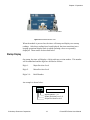
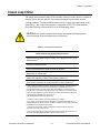
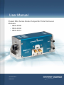
User Manual Pulsed REA Series Diode-Pumped Nd:YAG Rod Laser Modules REA-XX06 REA-XX08 REA-XX10 CEO-UMAN-0023B MARCH 2013 uble Shooting Guid Worldwide Technical Support and Product Information www.northropgrumman.com Search ceolaser Hours: 8:00 a.m. to 5:00 p.m., Central time* Service and Technical Support: (636) 916-4900 (follow prompts for department directory) Email: [email protected] Cutting Edge Optronics Headquarters 20 Point West Blvd. St. Charles, MO 63301 USA Sales Support: (636) 916-4900 (follow prompts for department directory) *After office hours, please leave a voice mail message. Outside North America, contact a Northrop Grumman Cutting Edge Optronics sales office or distributor; see the Northrop Grumman Cutting Edge Optronics website for a list of offices. © 2006 - 2013 Cutting Edge Optronics, a strategic business unit of Northrop Grumman Corporation. All rights reserved. © Northrop Grumman Corporation ii Pulsed REA Series User Manual Important Information Warranty Summary Northrop Grumman Cutting Edge Optronics (NG CEO) warrants that the products that it manufactures and sells will be free from defects in materials and workmanship for a period of one year from the date of shipment from an authorized NG CEO distributor. If a product proves defective within the respective period, NG CEO will provide repair or replacement as described in the complete warranty statement. To arrange for service or obtain a copy of the complete warranty statement, please contact your nearest NG CEO sales and service office. EXCEPT AS PROVIDED IN THIS SUMMARY OR THE APPLICABLE WARRANTY STATEMENT, NG CEO MAKES NO WARRANTY OF ANY KIND, EXPRESS OR IMPLIED, INCLUDING WITHOUT LIMITATION THE IMPLIED WARRANTIES OF MERCHANTABILITY AND FITNESS FOR A PARTICULAR PUPOSE. IN NO EVENT SHALL NG CEO BE LIABLE FOR INDIRECT, SPECIAL, OR CONSEQUENTIAL DAMAGES. Copyright Under the copyright laws, this publication may not be reproduced or transmitted in any form, electronic or mechanical, including photocopying, recording, storing in an information retrieval system, or translating, in whole or in part, without the prior written consent of NG CEO. Trademarks eDrive is a registered trademark of Northrop Grumman Corporation. Patents Northrop Grumman Corporation products are covered by U.S. and foreign patents, issued and pending. Information in this publication supersedes that in all previously published material. Specifications and price change privileges reserved. © Northrop Grumman Corporation iii Pulsed REA Series User Manual Safety Information Product End-of-Life Handling NG CEO is committed to protecting the environment. In accordance with the Waste Electrical and Electronic Equipment directive (WEEE) and Restriction of Hazardous Substances in the European Union (RoHS EU) directives, NG CEO accepts the return of our products for disposal. When you are ready to reclaim the instrument, you must properly transfer it according to local regulations concerning WEEE equipment. NG CEO or your local distributor for shipping instructions. Please package the products as directed for a return for repair. ROC ROHS Declaration In accordance with the Clause 6.2 of Marking for Control of Pollution Caused by Electronic Information Products (SJ/T11364:2006) for Measures for the Administration on Pollution Control of Electronic Information Products No. 39, Order of the Ministry of Information Industry of the Peoples Republic of China, NG CEO includes the following translation about our laser modules. © Northrop Grumman Corporation iv Pulsed REA Series User Manual Conventions The following conventions appear in this manual: This icon denotes a caution or a warning, which advise you of precautions to take to avoid injury, data loss, or a system crash. Initial Capped The first letter in uppercase refers to menu options, e.g., Phase Delay, Pulse Width. CAPS Front-panel buttons, knobs, and connectors appear in all uppercase letters, e.g., MENU, CURRENT. The symbol separates a sequence of button pushes, e.g., MENU CHANNEL SETUP PULSE WIDTH means that you push the MENU button, then push the CHANNEL SETUP soft key, and then push the PULSE WIDTH soft key. italic Italic text denotes references to other resources that may be helpful to you or to bring attention to important information. This icon denotes a note, which alerts you to important information. I O Power Switch Position Symbols I = On O = Off The following conventions may appear on the product: DANGER An injury hazard immediately accessible as you read the marking. WARNING A hazard not immediately accessible as you read the marking. CAUTION A hazard to property including the product. ESD: Handle Appropriately © Northrop Grumman Corporation v Pulsed REA Series User Manual Laser Emission: Use caution. Shock Hazard: Use caution. Caution: Risk of danger. Refer to manual. Chassis Ground © Northrop Grumman Corporation vi Pulsed REA Series User Manual General Safety Summary The Pulsed REA Series module emits laser radiation that can permanently damage eyes and skin, ignite fires, and vaporize substances. The Laser Safety section (Chapter 2) contains information and guidance about these hazards. To minimize the risk of injury or expensive repairs, carefully follow these instructions. Do not open the factory packaging before carefully reading this complete operation and maintenance manual. If you have any questions on the product which have not been discussed sufficiently within the manual, contact the manufacturer for complete instructions. Failure to heed this warning may result in the destruction or serious damage to the device, and will void the product warranty. The Service section is intended to help guide you to the source of problems. Do not attempt repairs while the unit is under warranty; instead, report all problems to NG CEO for warranty repair. Use the form in Appendix A: Customer Service to describe issues with the module. We also suggest that you record information about the module such as power, settings, time and date. © Northrop Grumman Corporation vii Pulsed REA Series User Manual About this Manual This manual describes the installation, operation, and service of the Pulsed REA Series module. The manual consists of the following chapters: Chapter 1: Introduction provides a theory of operation description of the module and specifications Chapter 2: Laser Safety describes proper safety procedures you should understand before operating the module. Chapter 3: Module Details provides information about unpacking, storing and proper environmental conditions for operation. Chapter 4: Maintenance provides information on proper maintenance of your module. Chapter 5: Service provides resources to help fix problems with the Pulsed REA Series module Appendix A: Customer Service provides information to expedite any service request before contacting NG CEO. Appendix B: System International Units identifies commonly used units of measurement found in this manual. Appendix C: Acronyms provides a list of commonly used abbreviations and their descriptions used throughout this manual. © Northrop Grumman Corporation viii Pulsed REA Series User Manual Table of Contents Chapter 1: Introduction 1 Theory of Operation 1 Temperature Tuning of Laser Diodes 2 REA-Series Description 4 High Voltage DC Power Supply 5 Closed Loop Re-circulating Distilled Water Chiller 5 Specifications 6 Chapter 2: Laser Safety 9 Caution & Warning Statements 10 Precautions for Safe Operation of Class IV Lasers 11 Center for Devices and Radiological Health (CDRH) OEM Product 12 Safety Device Checklist 13 Chapter 3: Module Details 14 Unpacking your Module 15 REA Series Module 15 REA Timer 17 Closed Loop Chiller 21 High Voltage DC Power Supply 25 Chapter 4: Maintenance 27 Rod Removal and Replacement 28 Rod Cleaning 32 High Voltage DC Power Supply Maintenance 32 © Northrop Grumman Corporation ix Pulsed REA Series User Manual Leak Test Procedure 32 Cleaning the Chiller 33 Chapter 5: Service 35 Contacting Customer Service 36 Return the Instrument for Repair 36 Appendix A: Customer Service 37 Questions 38 Appendix B: System International Units 40 Appendix C: Acronyms 41 © Northrop Grumman Corporation x Pulsed REA Series User Manual Table of Figures Figure 1-1 Exterior Components and Connections 1 Figure 1-2 Nd:YAG Absorption Characteristics 2 Figure 1-3 Pump Light Absorption vs. Pump Array Center Wavelength 3 Figure 1-4 Radial Pump Geometry 4 Table 1-2 End of life Waste Heat 6 Table 1-3 REA Series Model Specifications1 7 Table 1-4 REA Series General Specifications1 8 Figure 2-1 Standard Safety Warning Sign 12 Figure 2-2 Radiation Control Drawing 13 Figure 2-3 Warning Labels 13 Figure 3-1 Reverse Bias Protection Diode Circuit 17 Figure 3-2 REA Series Electronic Timer 18 Table 3-1. Cooling System Requirements 21 Table 3-2. Avoid with Chillers 22 Figure 3-3. Constant Dew Point Lines for Ambient Temperature and Relative Humidity 24 Table 3-3. Table of Air Condensation Temperature at Given Ambient Air Temperature (Celsius) and Relative Humidity (percent) 25 Figure 4-1 Rod Replacement Drawing, REA-XXXX-001X 28 Figure 4-2 Rod Replacement Drawing, REA-XXXX-002X 30 Figure 4-3 REA-XXXX-002X O-rings 31 Figure 4-4 Nitrogen Leak Test Layout 33 © Northrop Grumman Corporation xi Pulsed REA Series User Manual 1 Chapter 1: Introduction This introduction provides the following information: Theory of operation Temperature Tuning of Laser Diodes REA Series description High Voltage DC Power Supply Closed Loop Re-circulating Chiller Specifications © Northrop Grumman Corporation 1 Pulsed REA Series User Manual Chapter 1: Introduction Theory of Operation The REA Series module was designed for use as a building block “engine” in the development or production of medium power rod laser systems or as a drop-in replacement for arc lamp pump chambers in industrial lasers. It is well suited for medium power applications such as laser marking, and can provide high stability and beam quality for more precise micro-machining and scientific applications. Northrop Grumman Cutting Edge Optronics (NG CEO) diode pumped, solid-state lasers and pump modules use temperature-tuned GaAlAs laser diodes. These diodes replace arc lamps or incandescent light sources as the optical pump source. The principal advantages of this approach include: Longer lifetime More compact size More efficient operation The REA-Series module uses arrays of solid-state laser diodes to optically pump a neodymium-doped yttrium aluminum garnet (Nd:YAG) lasing medium. The diode optical output power is radially coupled into the laser rod. The Nd:YAG laser rod has an anti-reflection coating chosen for the highest gain wavelength of this material, 1064 nm. The REA-Series module is constructed within a durable and rigid structure. Exterior components and connections are shown in Figure 11. Figure 1-1 Exterior Components and Connections © Northrop Grumman Corporation 1 Pulsed REA Series User Manual Chapter 1: Introduction Temperature Tuning of Laser Diodes The laser diodes are located within the REA-Series module and tuned, wavelength matched, via the closed loop chiller. For maximum efficiency, the diode output wavelength must match the laser medium absorption characteristics (see Figure 12). The output spectrum of a conventional pump source for Nd:YAG operation, the xenon arc lamp, and 808 nm diode array is also shown. Figure 1-2 Nd:YAG Absorption Characteristics A single GaAlAs laser diode bar has a 2 nm FWHM distribution of output wavelengths. However, the process used in the manufacture of GaAlAs laser diodes results in a peak output wavelength for each diode that fits within a 10 nm distribution of wavelengths from 800-810 nm. To match the diode output to an absorption peak of the laser medium, diodes are selected with similar peak output wavelengths within the manufacturing range. Temperature tuning is possible because GaAlAs diode characteristics are such that 0.25 nm of wavelength shift occurs for every 1oC change in temperature of the diode junction. Cooling shortens the wavelength, and heating lengthens it. © Northrop Grumman Corporation 2 Pulsed REA Series User Manual Chapter 1: Introduction Figure 1-3 shows the percentage of pump light of different wavelengths absorbed by two passes through a 6.35 mm thick rod of 0.6% doped Nd:YAG. In NG CEO modules, the laser diode center wavelength, under normal operating conditions, is near the absorption peak of the laser medium. The operating temperature of closed loop chiller is carefully chosen to shift the diode temperature, so that the wavelength matches the absorption peak. The final test report, included with each module, indicates the optimum operation temperature for that module. Figure 1-3 Pump Light Absorption vs. Pump Array Center Wavelength © Northrop Grumman Corporation 3 Pulsed REA Series User Manual Chapter 1: Introduction REA-Series Description The REA-Series module utilizes a radial longitudinal pump geometry to excite the solid-state laser medium (see Figure 1-4). This pump geometry results in excellent gain uniformity and lensing performance. The reflector directs the divergent diode light back to the laser medium, which is kept in a flow tube for coolant circulation. The laser medium is a rod of neodymium-doped yttrium aluminum garnet (Nd:YAG). Both ends of the rod are optically polished and include anti reflection coatings at the lasing wavelength. The ends of the rod may be curved to compensate for thermal lensing, depending on module configuration. Figure 1-4 Radial Pump Geometry The REA comes in various physical configurations: 3.06 H x 3.66 W inches by 5.74 L, 6.57 L, or 7.40 L depending on model. The different lengths refer to different numbers of Array Sub-Modules (ASMs) on the five diode arrays that radially pump the rod. The shortest version has 6 ASMs per array, the middle 8 ASMs per array, and the longest has 10 ASMs per array. The different sized arrays are then available with different numbers of diode bars per ASM. . Finally, each of these different models is available with various size Nd:YAG rods from 4 mm diameter rods to 10 mm rods. The module part number indicates which options are chosen. The first two numeric digits indicate the diameter of the rod installed in the module. The second two digits indicate the number of ASMs per array. The number of bars per ASM is indicated by the number before the P in the part number. In other words, a REA5006-3P module has a 5.0 mm rod and six ASMs per array with three bars © Northrop Grumman Corporation 4 Pulsed REA Series User Manual Chapter 1: Introduction per ASM. Thus the module has a total of 90 diode bars (18 bars per array, arranged in 5 array) pumping power into the 5 mm YAG rod. High Voltage DC Power Supply A separate high voltage DC power supply is usually used to provide the DC voltage to run the diode arrays in an REA-Series module. Depending on customer usage requirements, NG CEO recommends different power supplies. Incoming AC voltage is converted to regulated DC voltage by the following process. The input AC voltage from facility power is rectified and filtered to produce an unregulated high voltage DC. This DC voltage is then converted by an inverter into a high frequency AC square wave. This waveform is stepped up or down by a high frequency isolation transformer. The secondary output is rectified and filtered to produce the required low ripple output voltage. The output is attenuated down and compared against a reference voltage, thus regulating the output. Regulation is achieved through modulation of the pulsewidth generated by the control stage. Closed Loop Re-circulating Distilled Water Chiller Coolant flow direction is polarized on the REA-Series pump module. Inlet and Outlet hose barbs are marked on the pumphead. Be sure to connect the coolant filter for the selected chiller on the Inlet connection, so only clean coolant from the filter flows through the pumphead. Dirty coolant deposits dirt on the Nd:YAG rod, which results in low output power. The module coolant loop is designed for an operating pressure of 50 psi. Chillers which deliver the required flow rate at lesser pressure do not provide adequate cooling. The selected chiller must have a heat capacity of greater than the waste heat for the specific model of REA-Series module. Depending on the model of REA module: the module length, number of bars per ASM, output power, and power consumption will vary. Therefore, NG CEO recommends different model of chiller depending on the number of diode bars in a module and the local electricity which will power the chiller. Table 1-2 gives the recommended chiller for some versions of the pulsed REA module. © Northrop Grumman Corporation 5 Pulsed REA Series User Manual Chapter 1: Introduction Table 1-2 End of life Waste Heat 60 Hz Electrical Outlets Model # of Bars REAXX06-2P REAXX06-3P REAXX06-4P REAXX08-2P REAXX08-3P REAXX08-4P REAXX10-2P REAXX10-3P REAXX10-4P 60 90 120 80 120 160 100 150 200 Volt per Bar 2.0 V 2.0 V 2.0 V 2.0 V 2.0 V 2.0 V 2.0 V 2.0 V 2.0 V EOL Current Duty Factor 70 A 70 A 70 A 70 A 70 A 70 A 70 A 70 A 70 A 20 % 20 % 20 % 20 % 20 % 20 % 20 % 20 % 20 % Waste Heat 1680W 2520W 3360W 2240W 3360W 4480W 2800W 4200W 5600W Polyscience Chiller No. 6762T41CE30D 6162T41CE30D 6862T66CE70D 6162T41CE30D 6862T66CE70D 6862T66CE70D 6162T41CE30D 6862T66CE70D Contact CEO Chiller Capacity 2500 W 2900 W 5200 W 2900 W 5200 W 5200 W 2900 W 5200 W 50 Hz Electrical Outlets Model # of Bars REAXX06-2P REAXX06-3P REAXX06-4P REAXX08-2P REAXX08-3P REAXX08-4P REAXX10-2P REAXX10-3P REAXX10-4P 60 90 120 80 120 160 100 150 200 Volt EOL per Current Bar 2.0 V 70 A 2.0 V 70 A 2.0 V 70 A 2.0 V 70 A 2.0 V 70 A 2.0 V 70 A 2.0 V 70 A 2.0 V 70 A 2.0 V 70 A Duty Factor Waste Heat Polyscience Chiller No. Chiller Capacity 20 % 20 % 20 % 20 % 20 % 20 % 20 % 20 % 20 % 1680W 2520W 3360W 2240W 3360W 4480W 2800W 4200W 5600W 6752T41CE30E 6852T66CE70E 6852T66CE70E 6852T66CE70E 6852T66CE70E Contact CEO 6852T66CE70E Contact CEO Contact CEO 2075 W 4316 W 4316 W 4316 W 4316 W 4316 W Specifications REA-Series modules are tested to exceed the following specifications. The standard production test configuration consists of a 280 ± 5 mm cavity utilizing a flat high reflector and a flat 70% reflective output coupler. © Northrop Grumman Corporation 6 Pulsed REA Series User Manual Chapter 1: Introduction Table 1-3 REA Series Model Specifications1 Model REA4006 REA4008 REA4010 Rod Size 4mm x 126mm 4mm x 146mm 4mm x 167mm 2P 120 160 200 3P 180 240 300 4P 240 320 400 2P 0-6250 0-8350 0-10400 3P 0-9400 0-12500 0-15600 4P 0-12500 0-16650 0-20800 Model REA5006 REA5008 REA5010 Rod Size 5mm x 126mm 5mm x 146mm 5mm x 167mm 2P 120 160 200 3P 180 240 300 4P 240 320 400 2P 0-6250 0-8350 0-10400 3P 0-9400 0-12500 0-15600 4P 0-12500 0-16650 0-20800 Model REA6306 REA6308 REA6310 Rod Size 6.35mm x 126mm 6.35mm x 146mm 6.35mm x 167mm 2P 120 160 200 3P 180 240 300 4P 240 320 400 2P 0-6250 0-8350 0-10400 3P 0-9400 0-12500 0-15600 4P 0-12500 0-16650 0-20800 Diode Bias Voltage (V) Power Consumption Diode Bias Voltage (V) Power Consumption Diode Bias Voltage (V) Power Consumption © Northrop Grumman Corporation 7 Pulsed REA Series User Manual Chapter 1: Introduction Table 1-4 REA Series General Specifications1 All Pulsed REA-Series Models 1 Type Pulsed Diode Pumped Nd:YAG Rod Dopant Level Application Dependent Output Wavelength 1064 nm Pulse Repetition Rate 1-2000 Hz Duty Cycle (Max) 15% Pointing Stability < 5% of cavity divergence Normal Peak Current 35-40 A Cooling Closed Loop Recycling Coolant Coolant Flow > 2.0 GPM 3 2 Coolant Pressure 50 PSI Operating Temperature 20-30 C non-condensing Optical Center from Base 1.50 inches Module Dimensions 3.06 H x 3.66 W x (5.74 L, 6.57 L, or 7.4 L) o 1 Specifications subject to change without notice 2 NG CEO recommends Optishield PlusTM /distilled water coolant (10% Optishield PlusTM, 90% distilled water). 3 NG CEO modules are leak tested to 80 psi with Nitrogen gas. NG CEO recommends 50 psi of chiller water for actual operation © Northrop Grumman Corporation 8 Pulsed REA Series User Manual 2 Chapter 2: Laser Safety Please read this section carefully before installing or operating your REA Series module. We recommend that all service and repair operations be performed by a NG CEO service engineer. If you do plan to service your laser module, please follow the procedures in the Service section of this manual. Sections included in this chapter provide the following information: Caution & Warning Statements Precautions for Safe Operation of Class IV Lasers Center for Devices and Radiological Health (CDRH) OEM Product Safety Device Checklist © Northrop Grumman Corporation 9 Pulsed REA Series User Manual Chapter 2: Laser Safety Caution & Warning Statements WARNING The NG CEO REA Series component when used as a laser oscillator is a Class IV-High Power Laser whose beam is, by definition, a safety hazard. Avoid eye or skin exposure to direct or scattered laser radiation. Avoid direct viewing of the beam or its specular reflection. When energized, a large amount of high power invisible laser radiation is emitted from the laser module. Follow instructions contained in this manual for proper installation and safe operation of your laser. We recommend the use of protective eyewear at all times; selection depends on the energy and wavelength of the laser beam as well as operating conditions. Consult ANSI, ACGIH, or OSHA standards for guidance. WARNING Use of controls, adjustments or performance of procedures other than those specified herein may result in hazardous radiation exposure. WARNING At all times during installation, operation, maintenance, or service of your laser, avoid exposure to laser or collateral radiation exceeding the accessible emission limits listed in “Performance Standards for Laser Products,” United States Code of Federal Regulations, 21 CFR 1040 10(d). ESD CAUTION The laser diodes in the REA Series are sensitive to Electro-Static Discharge (ESD). Never handle the REA Series module without being properly grounded through the use of properly installed and maintained grounding wrist straps or other ESD control devices. Subjecting the REA Series to static shock can seriously damage or destroy the diode bars, and will void the product warranty. ELECTRICAL WARNING The voltages in this system can be harmful or even lethal. Whenever handling or servicing the laser, always disconnect the power cord to the power supplies and drivers. Use a voltmeter to verify all electronics are discharged before touching or grounding of electrical connections. © Northrop Grumman Corporation 10 Pulsed REA Series User Manual Chapter 2: Laser Safety Precautions for Safe Operation of Class IV Lasers Never look directly into the laser beam or at specular reflection, even with protective eye-wear on. Always wear laser safety eye-wear that is appropriate for the output power at the wavelengths of operation (808 nm pump light and 1064 nm fundamental). Set aside a controlled-access area for laser operation; limit access to those trained in the principles of laser safety. Post readily readable warning signs in prominent locations near the laser operation area. Use safety interlocks on all entryways. All NG CEO system control electronics are provided with interlock inputs to preclude operation with an open safety door. NOTE: when multiple interlocks are used, they must be connected in SERIES for proper function. Restrict access to laser areas to those who have been instructed in the necessary safety precautions. Enclose beam paths wherever possible. Set up experiments so the laser beam is below eye level. Work in an area that is well lit to avoid dilation of pupils. Set up a target for the beam. Set up shields to prevent reflected beams from escaping the laser operation area. The Q-switched output power of the laser emits extremely high peak optical powers, powers that can severely damage a wide array of optical components and detectors. Know the limits of your components before exposing them to the Q-switched beam. View an infrared laser beam with a protected image converter at an oblique angle reflecting from a diffuse surface. Do not use phosphorus cards in the Qswitched beam. Ensure that all electrical connections are made in a safe manner. Where possible, position equipment so that electrical connections are shielded from accidental touch. No smoking, eating, or drinking should be allowed in laser areas. Never leave an operating laser unattended. © Northrop Grumman Corporation 11 Pulsed REA Series User Manual Chapter 2: Laser Safety Figure 2-1 Standard Safety Warning Sign Center for Devices and Radiological Health (CDRH) OEM Product The Pulsed REA-Series module is considered a component according to the Food and Drug Administration, Code of Federal Regulations Title 21, Section 1002.1(b) for use in an end system, and therefore does not fully comply with all the requirements of the Code of Federal Regulations for laser-based systems. The Pulsed REA-Series module is capable of emitting Class IV radiation, and extreme care must be exercised in its installation and operation. Only persons familiar with the safety precautions and practices in this manual should operate the laser product. © Northrop Grumman Corporation 12 Pulsed REA Series User Manual Chapter 2: Laser Safety Figure 2-2 Radiation Control Drawing Figure 2-3 Warning Labels Safety Device Checklist 1. Verify that all labels are securely affixed. 2. Verify that the safety interlock system is working properly. 3. Locate the module so that operation of laser and/or adjustment of control electronics do not require exposure to laser radiation. © Northrop Grumman Corporation 13 Pulsed REA Series User Manual 3 Chapter 3: Module Details This chapter describes basic operation of your REA Series module. This chapter discusses: Unpacking your Module REA Series Module REA Timer Closed Loop Chiller High Voltage DC Power Supply © Northrop Grumman Corporation 14 Pulsed REA Series User Manual Chapter 3: Operation Unpacking your Module Your NG CEO Pulsed REA Series module was carefully packed for shipment. If the carton appears to have been damaged in transit, have the shipper’s agent present when you unpack. CAUTION The module is susceptible to damage due to electro-static discharge (ESD). Always use proper ESD control devices when handling the module. CAUTION Do not open sealed package until package has normalized to room temperature. Condensation can seriously damage the diode arrays in the laser module and may void warranty. Inspect the unit as you unpack it, looking for dents, scratches, or other evidence of damage. If you discover any damage, immediately file a claim against the carrier and notify your NG CEO representative. NG CEO will arrange for repair without waiting for settlement of your claim. Keep the shipping container. If you file a damage claim, you may need it to demonstrate that the damage occurred as a result of shipping. If you need to return the unit for service, the specially designed carton assures adequate protection. A manual and a final test report should accompany each unit shipped. REA Series Module Proper storage of the REA Series module involves four steps: 1. Remove all coolant from module by blowing dry air through it for 20 minutes. 2. Place a shorting connector across the module electrical contacts. 3. Install rod end covers over both beam tube supports. 4. Store module in a clean, dry atmosphere (relative humidity less than 30%). If necessary, place module in a sealed bag with some form of desiccant. The approximate diode bias voltage for the different models of REA-Series module can be found in the Specifications table at the end of chapter one. The electrical system should deliver approximately 10 more volts, depending on the FET used. The Pulsed REA-Series module is designed for a variable current (peak current of 45 A). The pulsed diodes can operate with a maximum duty cycle of 20%. The pulse width can be varied up to a maximum of 250 microseconds and the pulse repetition frequency can be set within a range of 1-2000 Hz, as long as the total duty cycle does not exceed the 20 % limit. © Northrop Grumman Corporation 15 Pulsed REA Series User Manual Chapter 3: Operation The REA-Series module connects to a diode driver in via power lugs on the base of the pumphead module. The diode arrays within the REA-Series module are aligned and sealed at the factory. Other than the laser rod, there are no user serviceable parts within the module. Contact a NG CEO field service engineer for repairs. Before lasing, the operator should verify that rod faces are clean. If necessary, the rod faces can be cleaned by following the procedure in the maintenance section of this manual. Reverse Bias Protection Diodes are polarized with respect to electrical flow. A forward biased diode readily conducts; while a reverse biased diode blocks conduction. If sufficient voltage is applied in the reverse direction, the diode is permanently damaged. Laser diodes are the single most expensive component of a REA Series module, so the customer should be careful to connect diode drive current correctly. In order to provide the REA Series modules with some protection against reverse biasing, all REA Series modules are equipped with a reverse protection diode. This is another diode, usually located in the module, which forms a circuit across the laser diode arrays in the opposite flow direction (Figure 3-1). In the event of the laser diode drive current being reversed, the reverse bias protection diode will act like a short circuit, allowing the electricity to flow for a brief time with no resistance. However, the reverse bias protection diode is not able to withstand the high currents that laser diodes require. The protection diode will burn out after a brief time, and the drive current will be sent through the laser diodes in reverse. © Northrop Grumman Corporation 16 Pulsed REA Series User Manual Chapter 3: Operation Figure 3-1 Reverse Bias Protection Diode Circuit NG CEO drive electronics are designed to detect the shorted reverse protection diode, and suspend drive current before damaging the laser diodes. Customers who use third party manufactured drive electronics must configure them for use with NG CEOs reverse bias protection diodes. The driver should be able to detect the shorted condition because with a short across the array, the full power supply voltage will suddenly be impressed across the driver control FETs. For drivers which have a fixed power supply voltage, a much larger voltage across the drive FETs will increase the heat load and cause a dramatic rise in their temperature. For third-party drivers which have the capability to servo the voltage to produce the necessary current, a sudden decrease in output voltage should cause a corresponding large decrease in the voltage required internally within the driver, which could be detected and reported. If any of the conditions are detected, the driver should suspend diode drive current and send the operator an error message. REA Timer The REA Series module includes an electronic timer circuit which monitors the operation of the pump head and tracks the number of hours of operation, the number of pulsed shots, and the number of on/off cycles over the lifetime of the head. These data may be displayed to the user on a 4-digit LCD display on the front of the module. This timer is powered by the applied module operating voltage and will only be operational when the module is operating. © Northrop Grumman Corporation 17 Pulsed REA Series User Manual Chapter 3: Operation Timer LCD Readout Figure 3-2 REA Series Electronic Timer When the module is powered on, the timer will startup and displays two startup readings. After these readings have been displayed, the timer transitions into a looping operational display mode in which operating values are repeatedly displayed. These modes are described below. Startup Display On startup, the timer will display a 4-digit software revision number. This number will be underlined and the digits are decoded as follows: Digit 1: Major Revision Level Digit 2: Minor Revision Level Digits 3-4: Build Number An example is shown below: 1025 Version 1.0.25 Build Number = 25 Minor Revision Level = 0 Major Revision Level=1 © Northrop Grumman Corporation 18 Pulsed REA Series User Manual Chapter 3: Operation After 2-3 seconds, the display will then display the number of power on/off cycles which have occurred and the underline will be turned off. This count is not the number of shots or pulses which have been generated by the module, but instead is the number of times the module has gone from an inactive state to an active state. This number is incremented each time the timer goes through its startup routines. After a short delay, the timer will transition to a repeating operational display mode. This is described below. Operational Display In this mode, the timer displays a sequence start indicator followed by up to three timer values depending on the operating mode and the configuration which was applied at the factory. These are described below. Sequence Start Indicator In order to indicate the beginning of the display sequence, the timer displays the Sequence Start Indicator. The display briefly shows the following readout: −−−− First Readout Value The next value displayed is the module hour counter. This displays the number of hours the module has been operating. If the number of hours exceeds 9999, then the display will scroll to the left to show the additional digits. Second Readout Value The second value displayed in the sequence can be one of two values depending on the operating mode. If the pump head is being operated in CW mode, then the display will again report the number of operating hours. If the module is being pulsed, then the display will show the number of shots or pulses which the module has generated. See the description below for an explanation of the meaning of the shot counter display. Optional Third Readout Value The third value which is displayed is an optional value which is configured at the factory when the module is built. Contact NG CEO for information about the values which can be selected. If no value is selected, this display value is skipped and the © Northrop Grumman Corporation 19 Pulsed REA Series User Manual Chapter 3: Operation display cycle starts over. Typically, the module will be programmed to display the on/off cycle count in this third position. After displaying all of these values, the cycle will repeat with the display of the sequence start indicator. Shot Count Display: The shot counter display is capable of displaying a very large number of shots with 3 significant figures. The first 3 digits of the shot count represent the first 3 digits of the number of shots. The fourth digit represents the number of zeros to place behind this 3 digit number. For example, if the readout showed 8385 this would represent approximately 83,800,000 shots. If the value shown has a line beneath it, such as 1480 then the fourth digit should be increased by 10 to determine the number of zeros. In this case, the shot count would be approximately 1,480,000,000,000 © Northrop Grumman Corporation 20 Pulsed REA Series User Manual Chapter 3: Operation Closed Loop Chiller The single most common cause of laser module return for repair involves customer damage. More than one third of all customer damaged laser modules involve cooling problems. Coolant problems almost always require the replacement of the diode arrays - the single most expensive component in NG CEO laser modules. Read the following section carefully to avoid damaging arrays. CAUTION Do not operate module without cooling. Inadequate heat dissipation will seriously damage the laser diodes and will void warranty. Table 3-1. Cooling System Requirements Chiller and Cooling System Requirements Optishield PlusTM /distilled water coolant (10% Optishield PlusTM, 90% 1, 2 distilled water) Coolant circulated at 50 psi. Filter connected between chiller and inlet on module 3, 4 Module first in coolant loop 5 Chiller Heat Capacity > Power Consumption (Table 1-2) Flow sensor (connected to coolant interlock on drive electronics) 6 1 Clean coolant is important to keeping coolant lines from clogging. Untreated tap water is not an acceptable coolant and may cause damage. Optishield PlusTM is the recommended coolant. It is made from DI water with additives to control the pH. By using DI water in the solution, scale will not form in the cooling loop. It contains biocide to prevent algae growth and corrosion inhibitors to protect yellow metals and aluminum. 2 Optishield Plus is available from Opti Temp, Inc (http://www.optishield.net/home.php?cat=103). 3 The filter should be capable of removing particles 5 μm or larger. 4 Every month, or whenever the filter is changed, the coolant should be drained. The chiller should then be cleaned. The filter should be changed more frequently if the chiller manufacturer recommends a shorter interval. 5 This ensures the cleanest, coolest coolant passes through the diodes (the most expensive component of most lasers). 6 When not using NG CEO drive electronics, verify that flow sensor interrupts current to diodes less than 500 milliseconds after a low flow condition occurs. © Northrop Grumman Corporation 21 Pulsed REA Series User Manual Chapter 3: Operation Table 3-2. Avoid with Chillers Avoid with Chillers Untreated De-ionized water1 Iron or aluminum parts in plumbing loop Operation below air condensation temperature NG CEO recommends chiller water have a resistivity of less than 1.0 MΩ. Deionized water can be used if the resistivity is closely monitored and the coolant loop does not have iron or aluminum parts. 1 Operating the Chiller WARNING. Do not operate module without cooling. Inadequate heat dissipation will seriously damage the laser diodes and will void warranty. If you notice coolant in the immediate vicinity of the module, shut the laser system down immediately. Check to see if the coolant is coming from the module. If so, return the module for repair. If not, repair the source of the leak and allow the module to dry thoroughly before resuming operation. The REA-Series module has a coolant loop to prevent thermal damage to the laser diodes. The diodes should be kept at approximately 20-35 °C. See the final test report for optimum temperature and flow rate settings. Operating the laser diodes for even a short period of time (less than 1 second) without coolant will cause permanent damage. To help prevent this, all NG CEO drive electronics are equipped with a coolant interlock. This interlock interrupts drive current to the diodes when coolant flow rate drops below set point. For this to function properly, a flow sensor must be used in the coolant loop. It is a good idea to test the function of the flow sensor before firing when first setting up the laser system. This can be accomplished by setting the drive current to a very low level (~ 1 A) then attempting to fire the laser with the chiller off. In case interlock does not function correctly, be prepared to manually turn off laser. By testing the interlock with a minimal current, the risk to the laser diodes is minimized. WARNING. Do not operate the coolant system below air condensation temperature (dew point) at the laser head. Condensation on the diode arrays can seriously damage the laser head and will void the warranty. Consult a NG CEO field service engineer if you have any questions. Air Condensation Temperature The air condensation temperature (or dew point) is the highest surface temperature that allows water to form from the ambient water vapor. The dew point is dependent © Northrop Grumman Corporation 22 Pulsed REA Series User Manual Chapter 3: Operation on the surrounding air temperature and relative humidity. If a surface (such as a laser diode) is cooled at or below the condensation temperature, water may collect on that surface. A formula for calculating dew point is given below, along with a calculated table. All temperatures are given in Celsius. Condensation Temperature Td = 237.7 × α (T , RH ) 17.27 − α (T , RH ) α (T , RH ) = 17.27 × T RH + ln 237.7 + T 100 where T is the ambient air temperature in degrees Celsius (0 < T < 60) RH is the relative humidity in percent (1% < RH < 100%) Td is the air condensation temperature For example, suppose your chiller is running at 22 °C and the ambient air temperature near the laser is 28 °C (82 °F). Referring to Figure 3-3 and Table 3-3, find the intersection of the 28 °C air temperature and the curve for the 22 °C diode temperature. At a relative humidity of 70 percent or greater, condensation will form on the laser diodes. © Northrop Grumman Corporation 23 Pulsed REA Series User Manual Chapter 3: Operation Figure 3-3. Constant Dew Point Lines for Ambient Temperature and Relative Humidity © Northrop Grumman Corporation 24 Pulsed REA Series User Manual Chapter 3: Operation Table 3-3. Table of Air Condensation Temperature at Given Ambient Air Temperature (Celsius) and Relative Humidity (percent) 1% 10% 20% 30% 40% 50% 60% 70% 80% 90% 100% 10 -43.9 -20.2 -11.9 -6.8 -3.0 0.1 2.6 4.8 6.7 8.4 10.0 12 -42.6 -18.7 -10.3 -5.0 -1.2 1.9 4.5 6.7 8.7 10.4 12.0 14 -41.4 -17.1 -8.6 -3.3 0.6 3.7 6.4 8.6 10.6 12.4 14.0 16 -40.2 -15.6 -7.0 -1.6 2.4 5.6 8.2 10.5 12.5 14.4 16.0 18 -39.0 -14.1 -5.3 0.2 4.2 7.4 10.1 12.4 14.5 16.3 18.0 20 -37.8 -12.5 -3.6 1.9 6.0 9.3 12.0 14.4 16.4 18.3 20.0 22 -36.6 -11.0 -2.0 3.6 7.8 11.1 13.9 16.3 18.4 20.3 22.0 24 -35.4 -9.5 -0.4 5.3 9.6 12.9 15.7 18.2 20.3 22.3 24.0 26 -34.2 -8.0 1.3 7.1 11.3 14.8 17.6 20.1 22.3 24.2 26.0 28 -33.0 -6.5 2.9 8.8 13.1 16.6 19.5 22.0 24.2 26.2 28.0 30 -31.8 -4.9 4.6 10.5 14.9 18.4 21.4 23.9 26.2 28.2 30.0 32 -30.6 -3.4 6.2 12.2 16.7 20.3 23.2 25.8 28.1 30.1 32.0 34 -29.5 -1.9 7.8 13.9 18.5 22.1 25.1 27.7 30.0 32.1 34.0 36 -28.3 -0.4 9.5 15.7 20.2 23.9 27.0 29.6 32.0 34.1 36.0 38 -27.1 1.1 11.1 17.4 22.0 25.7 28.9 31.6 33.9 36.1 38.0 40 -26.0 2.6 12.7 19.1 23.8 27.6 30.7 33.5 35.9 38.0 40.0 o Air Temperature C Relative Humidity If required to operate a laser in conditions near to the condensation temperature, take precautions to keep the REA Series module dry. The module should be operated inside an area that is purged with nitrogen (N2) or encased in a sealed enclosure with a desiccant. High Voltage DC Power Supply The REA-SeriesTM requires a high voltage DC power supply to provide electricity to the laser diodes. The chosen power supply should be regulated. Unregulated supplies tend to either drop below the minimum voltage required to maintain regulation, or to sit at an unnecessarily high voltage at lower currents, causing FET overheating. The chosen power supply should be capable of providing the voltage mentioned in the specifications table at the end of Chapter 1. It must provide this voltage at 27 A © Northrop Grumman Corporation 25 Pulsed REA Series User Manual Chapter 3: Operation of current. Ideally, the power supply should be capable of currents up to 38 A, since the diodes usually require higher currents at the end of their useful life. NG CEO Drivers can tolerate a large amount of ripple, since the pass FET typically filters this out. However, ripple should not exceed +/- 0.5 volt at full output current. WARNING. Hazardous voltages are present during normal operation. Before removing the cover, the power source should be disconnected and a period of 20 minutes allowed for the discharge of stored capacitance. Use a voltmeter to verify all electronics are discharged before touching or grounding of electrical connections. © Northrop Grumman Corporation 26 Pulsed REA Series User Manual 4 Chapter 4: Maintenance The chapter contains information in these sections: Rod Removal and Replacement Rod Cleaning High Voltage DC Power Supply Maintenance Leak Test Procedure Cleaning the Chiller © Northrop Grumman Corporation 27 Pulsed REA Series User Manual Chapter 4: Maintenance Rod Removal and Replacement The only user serviceable part in the REA Series module is the Nd:YAG rod, which can be replaced by the user. YAG rods rarely break, frequent replacement may be a sign of another problem in the REA Series module. Contact NG CEO if you have any further questions. CAUTION. The module is susceptible to damage due to electro-static discharge (ESD). Always use proper ESD control devices when handling the module. CAUTION. Ensure gloves or finger cots are worn during this procedure and that it is carried out in a clean environment, preferably under a laminar flow hood. REA-XXXX-001X Configuration Figure 4-1 Rod Replacement Drawing, REA-XXXX-001X 1. Remove four fasteners releasing Macor shields. 2. Remove the two retainer caps from the ends of the module. CAUTION. Use extreme caution during the remaining steps of this procedure to insure that the rod faces and/or coatings are not damaged. Never use a tool that can scratch the rod on the O-rings. 3. Extract one of the O-rings that hold the rod in place using a dental pick or other similar tool. Stick the sharp end of the dental pick into the O-ring and pull away from the pump module. New O-rings will be used during the installation of the © Northrop Grumman Corporation 28 Pulsed REA Series User Manual Chapter 4: Maintenance new rod. Be very careful not to damage the rod ends, or barrel, with the extraction tool. 4. Remove the rod by applying slight pressure in order to break the O-ring seal on the opposite end. Partial extraction of the O-ring on the opposite end may be needed. If necessary, loosen the O-ring with the dental pick. Once again, be careful not to damage the rod ends, or barrel. 5. Unwrap the new rod and inspect the end faces. 6. Obtain two#007 white Viton O-rings when using a 4mm diameter rod, two #008 white Viton O-rings when using a 5mm diameter rod, or two #010 white Viton O-rings when using a 6.35mm diameter rod. 7. Place one of the corresponding O-rings over one end of the rod. Position the Oring inside the O-ring groove on the end plate. 8. Insert the opposite end of the rod into the corresponding hole in one end of the module until it protrudes from the hole in the opposite end. Center the rod. The rod is very fragile. Be careful not to chip or scratch the rod while inserting it. 9. Place one of the retainer caps over the end of the rod with the O-ring. Attach via the hardware removed during disassembly. 10. Place the second white O-ring over the opposite end of the rod. Slide O-ring along rod into O-ring groove in endplate. 11. Inspect this rod end for cleanliness. If needed, clean the end of the rod with methanol and cotton swabs 12. Attach the second retainer cap onto the pump module. 13. Position the rod equidistant from each end of the pump module using the soft end of a cotton swab. 14. Reinstall Macor shields. Ensure that the gap is minimal between Macor shield and laser rod. The Macor shields protect the retainer nut and O-rings from stray laser radiation. 15. Inspect both rod ends for cleanliness. If necessary, clean the ends of the rod with a puff of dry nitrogen or moisture-free canned air. 16. Leak test according to the following procedure. Alternately, turn on the chiller and allow coolant to flow for approximately 20 minutes. Examine pump module for leaks. 17. If pumphead leaked: first fix the leak, then test again for leaks, finally allow module to dry thoroughly before lasing. Firing wet diodes will permanently damage them. © Northrop Grumman Corporation 29 Pulsed REA Series User Manual Chapter 4: Maintenance REA-XXXX-002X Configuration Figure 4-2 Rod Replacement Drawing, REA-XXXX-002X 1. Remove beam tube supports and the Macor shields from both ends of the rod. CAUTION. Use extreme caution during the remaining steps of this procedure to insure that the rod faces and/or coatings are not damaged. Never use a tool that can scratch the rod on the O-rings. 2. Starting with the end of the module without the hose barbs apply methanol to the rod o-ring. 3. Remove the six screws that hold the insert to the endplate and then slowly rotate and pull the insert off the rod. 4. Moving to the other end of the module with the hose barbs remove the six screws holding the insert to the endplate and pull the insert and rod out of the module. 5. Apply methanol to the rod o-ring and remove the second insert. 6. Remove rod from its packaging and inspect end faces under 50X magnification. 7. Inspect rod o-rings in the center of the inserts, if no damage is found reuse the original o-rings but if damage is found obtain two #10 white o-rings if using a 6.35mm diameter rod, two #8 white o-rings if using a 5mm wide rod or two #7 white o-rings if using a 4mm wide rod and replace the original o-rings. 8. Each insert has one large o-ring groove on the surface near the edge of the insert this is the inside surface of the insert, Figure 5-3 shows correct installation of the #28 black o-ring into this groove. 9. Lubricate both white o-rings in the center of the inserts and both #28 black orings with the syringe of methanol. © Northrop Grumman Corporation 30 Pulsed REA Series User Manual Chapter 4: Maintenance 10. Place a #15 black medium o-ring in the matching groove on the right endplate of the module, as shown in Figure 5-3, that has the two hose barbs and then lubricate with the methanol syringe. Figure 4-3 REA-XXXX-002X O-rings 11. Push the rod through the white o-ring in the center bore of one insert from the inside surface side of the insert until it sticks past and out the other side about 1/8” making sure not to shave or cut the white o-ring. 12. Holding the rod with one insert on it carefully slide the end without the insert in to the center bore of the hose barbed end plate until the rod comes out the other end of the module, being careful not to hit the rod end on the endplate. 13. Holding the insert up against the hose barbed endplate so it is flat and level place a gloved fingertip over the rod to keep it from being pushed out in step 14. 14. With one hand held as stated in step 13, use the other hand to push the second insert onto the exposed rod end making sure the white o-ring is not damaged as the rod passes through the center bore of the insert and the #28 black o-ring faces the endplate. 15. Once the inserts are pushed safely onto the rod ends they should lay flush with each of their endplates of the module with the #28 black o-rings as the seal between the two pieces. 16. Fasten each of the two inserts to their endplates with five #4 sized 3/8” SHC Screws and one #4 sized 3/8” BHC Screw that goes in the slotted hole, shown in Figure 5-3, of each insert. 17. Clean the rod ends at 50x with canned air and methanol soaked q-tips 18. Reattach the Macor shields. 19. Double check the rod ends with a microscope after the Macor shields are in place to ensure the rod ends are still clean. Then replace the beam tube supports. © Northrop Grumman Corporation 31 Pulsed REA Series User Manual Chapter 4: Maintenance Rod Cleaning CAUTION. Ensure gloves or finger cots are worn during this procedure and that it is carried out in a clean environment, preferably under a laminar flow hood. 1. Blow optical surface with dry nitrogen 2. Remove four fasteners releasing Macor shields. 3. Using hemostats and lens tissue, wetted with acetone or methanol, wipe the rod face in a circular motion from the center of the rod to the edges. 4. Inspect the rod for cleanliness. 5. Reinstall Macor shields. Ensure that the gap is minimal between Macor shield and laser rod. The Macor shields protect the retainer nut and O-rings from stray laser radiation. High Voltage DC Power Supply Maintenance A regularly scheduled maintenance of once a year is recommended for HV power supplies. As a minimum, maintenance should consist of a thorough cleaning of the interior and a visual inspection of the fans and components on the printed circuit board. Periodic calibration is also recommended. Consult power supply manual for details. WARNING. Hazardous voltages are present during normal operation. Before removing the cover, the power source should be disconnected and a period of 20 minutes allowed for the discharge of stored capacitance. Use a voltmeter to verify all electronics are discharged before touching or grounding of electrical connections. Leak Test Procedure Laser diodes are very sensitive to water damage. If you have access to pressurized nitrogen and a pressure gage, you can test for leaks without exposing the diodes to water. 1. Attach a nitrogen source to one of the coolant ports on the module being tested (test article) and attach the termination valve to the other coolant port on the test article. 2. Close the termination valve. © Northrop Grumman Corporation 32 Pulsed REA Series User Manual Chapter 4: Maintenance 3. Open the inlet valve and adjust the regulator to obtain 80 psi on the pressure gauge. 4. Close the inlet valve. Wait. 5. Return after 30 minutes and record pressure on the gauge. Subtract this pressure from starting pressure of 80 psi to get the pressure drop over 30 minutes. 6. Pass/Fail requirements: if the pressure drop is greater than 3 psi FAIL, if the pressure drop is less than 3 psi PASS. Figure 4-4 Nitrogen Leak Test Layout Cleaning the Chiller The cooling fluid should run for a maximum period of 1 month after which the system should be drained, cleaned and refilled with clean coolant. The filter on the closed loop system should be monitored weekly. The system should also be drained, cleaned and refilled with clean coolant if any discoloration of the filter occurs. Chemicals and Supplies Needed 3% Hydrogen Peroxide solution sufficient to fill the system. Optishield PlusTM and distilled water solution (10% Optishield PlusTM, 90% distilled water). Distilled water, sufficient to fill the system. Two replacement particle filters (NGCEO part # 37023165). Cleaning Procedure 1. Drain chiller and clean any residue or contamination in the reservoir with the use of a bottle brush or alcohol wipes. 2. Using a filter housing wrench, dismantle the particle filter housing. Empty the coolant trapped in the filter housing into a container for later disposal. 3. Dispose of the expired particle filter and clean any residue or contamination from the inside of the filter housing. Install a new filter in the housing. 4. Refill with distilled water and circulate for 5 minutes. © Northrop Grumman Corporation 33 Pulsed REA Series User Manual Chapter 4: Maintenance 5. Drain system completely as detailed in steps 1 and 2. 6. Fill the chiller with a 3% solution of Hydrogen Peroxide. Care should be taken to ensure that the mixture completely fills to the top of the reservoir to ensure all wetted surface areas of the chillers are cleaned. Cycle the chiller on and off. Top off the reservoir as necessary to ensure it is full of the cleaning solution. Ensure that the cap of the chiller reservoir is loose or remove it completely to allow gas to escape from the system. 7. Circulate the cleaning solution through the system including the diode pump module for 40 minutes. 8. Drain the cleaning solution mixture from the chiller as detailed in steps 1 and 2. 9. Refill and circulate distilled water for 5 minutes and drain. Ensure that the cap of the chiller reservoir is loose, or remove it completely to allow gas to escape from the system. 10. Drain the chiller and dispose of the filter. 11. Disconnect the chiller from the diode pump module and blow out water from the diode pump module coolant loop prior to refilling the chiller coolant reservoir. 12. Reconnect the diode pump module coolant loop. 13. Install new 5 micron filter into housing. 14. Record cleaning date on sticker with a one-month reminder to drain & clean the system. Affix sticker to chiller (or cabinet). 15. Refill the chiller reservoir with Optishield plus and distilled water coolant following the manufacturer’s directions. Run for 30 minutes with the cap loose to allow gas to escape from the system. 16. Secure the reservoir cap. It should have a 0.125 inch (~3mm) diameter hole in it to allow the cooling system to vent. A hole should be drilled into the reservoir cap if one is not already present. 17. Chiller ready to use. © Northrop Grumman Corporation 34 Pulsed REA Series User Manual 5 Chapter 5: Service At Northrop Grumman Cutting Edge Optronics, we are proud of the durability of our products. Our manufacturing and quality control processes emphasize consistency, ruggedness, and high performance. Nevertheless, even the finest instruments break down occasionally. We believe that the reliability record of our instruments compares favorably with that of our competition, and we hope to demonstrate our superior service by providing dependable instruments and, if the need arises, service facilities that can restore your instrument to peak performance without delay. When calling for service in the U.S., dial (636) 916-4900. To phone for service in other countries, contact your sales agent. This chapter provides reference to types of customer service needs: Contacting customer service Return the instrument for repair © Northrop Grumman Corporation 35 Pulsed REA Series User Manual Chapter 5: Service Contacting Customer Service To expedite your service needs, please complete the questionnaire in Appendix A: Customer Service before you contact NG CEO Customer Service. Complete the questionnaire with as much detail as possible and retain a copy for your records. E-mail or fax the form to NG CEO (refer to the second page of this manual for contact information) and notify your customer service representative that it has been sent. Return the Instrument for Repair A return merchandise authorization (RMA) is required prior to shipping any instruments to NG CEO. Contact NG CEO or your local distributor for RMA and shipping instructions. CAUTION. Failure to obtain proper shipping instructions may result in damage to the instrument. Use the packing boxes supplied by NG CEO to ship your instruments. If shipping boxes have been lost or destroyed, replacements are available for a nominal charge from NG CEO. Remove all coolant from module by blowing dry air through it for 20 minutes, prior to packaging for shipment. Place a shorting connector across the electrical connector (see example Figure 1-1). Place module in a sealed bag inside shipping container. Place some form of desiccant in bag with module. WARNING . Damage from residual water due to condensation or expansion can be catastrophic to the diode arrays or laser rod if not dealt with properly. Such damage is excluded from warranty coverage. © Northrop Grumman Corporation 36 Pulsed REA Series User Manual A Appendix A: Customer Service This form has been provided to encourage you to tell us about any difficulties you may have experienced while using your Northrop Grumman Cutting Edge Optronics instruments or user manuals. Call or write our customer service department to bring attention to problems that you may not have personally experienced. We are always interested in improving our products and manuals, and we appreciate all suggestions. Date: Name: Company or Institution: Department: Address: Module Model Number: Serial Number: Chiller Model Number: Serial Number: External Power Supply Model Number: Serial Number: eDrive Model Number: Serial Number: Module Manufacture Date: Total Module Lifetime (hours): © Northrop Grumman Corporation 37 Pulsed REA Series User Manual Appendix A: Customer Service Questions What is the coolant flow rate (GPM)? o What is the set temperature on the chiller ( C)? What is the coolant pressure on chiller (PSI)? What are the set current and actual current from eDrive (A)? What is the external power supply voltage (V)? What is the laser cavity configuration? What is the measured CW power (W)? When did the problem happen? Have you changed any settings recently (yes/no)? © Northrop Grumman Corporation 38 Pulsed REA Series User Manual Appendix A: Customer Service What are the changes made recently to the system? Please describe the problem or module behavior as detailed as possible: Suggestions Email or send to: Northrop Grumman Cutting Edge Optronics, Inc. 20 Point West Boulevard Saint Charles, MO 63301 USA Phone: (636) 916-4900 FAX: 636-916-4994 Email: [email protected] © Northrop Grumman Corporation 39 Pulsed REA Series User Manual B Appendix B: System International Units The following System International (SI) units, abbreviations, and prefixes are used throughout NG CEO user manuals: Quantity Unit Symbol Abbrv. Prefixes 12 T 9 G 6 M (10 ) 3 k -1 d -2 c -3 m -6 µ (10 ) -9 n -12 p -15 f -18 a mass gram g tera (10 ) length meter m giga (10 ) time second s mega (10 ) frequency Hertz Hz kilo force Newton N deci (10 ) energy Joule J centi (10 ) power Watt W milli (10 ) electric current Ampere A micro (10 ) electric charge Coulomb C nano electric potential Volt V pico (10 ) resistance ohm Ω femto (10 ) inductance Henry H atto (10 ) magnetic flux Weber Wb magnetic flux density Tesla T luminous intensity candela cd temperature Kelvin K © Northrop Grumman Corporation 40 Pulsed REA Series User Manual C Appendix C: Acronyms Acronym Description ACGIH American Council of Government Industrial Hygienists ANSI American National Standards Institute AR Anti-Reflective AO Acusto-Optical (type of Q-switch) CDRH Center for Devices and Radiological Health - U.S. Food and Drug Administration CEO Cutting Edge Optronics, Incorporated CFR Code of Federal Regulations CW Continuous Wave DC Direct Current EO Electro-Optical (type of Q-switch) ESD Electro-Static Discharge FET Field Effect Transistor FDA U.S. Food and Drug Administration FWHM Full Width - Half Max GaAlAs Gallium Aluminum Arsenide GPM Gallons Per Minute HR High Reflector HV High Voltage IR Infrared KTP Potassium Titanyl Phosphate LBO Lithium Triborate © Northrop Grumman Corporation 41 Pulsed REA Series User Manual Appendix C: Acronyms Acronym Description MCC Meters Concave Nd:YAG Neodymium-doped Yttrium Aluminum Garnet NG Northrop Grumman NIR Near Infrared OSHA Occupational Safety and Health Administration PRF Pulse Repetition Frequency PSI Pounds per Square Inch SHG Second Harmonic Generator TTL Transistor - Transistor Logic VAC Volts, Alternating Current © Northrop Grumman Corporation 42 Pulsed REA Series User Manual