1
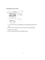
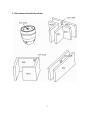
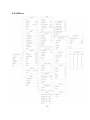
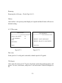
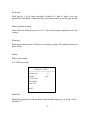
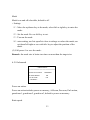
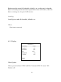
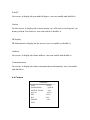
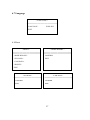
WARNINGS AND CAUTIONS
WARNING
TO REDUCE THE RISK OF FIRE OR ELECTRIC SHOCK, DO NOT
EXPOSE THIS PRODUCT TO RAIN OR MOISTURE. DO NOT INSERT
ANY METALLIC OBJECTS THROUGH VENTILATION GRILLS OR
OPENINGS ON THE EQUIPMENT.
CAUTION
EXPLANATION OF GRAPHICAL SYMBOLS
The lighting flash with arrowhead symbol, within an equilateral
triangle, is intended to alert the user the presence of non-insulated
“dangerous voltage” within the product’s enclosure that maybe of
sufficient magnitude to constitute a risk of electric shock to different
persons.
The exclamation point within an equilateral triangle, is intended
to alert the user the presence of important operating and
maintenance (servicing) instructions in the literature
accompanying this product
1
PRECAUTIONS:
1. Persons without technical qualifications should not attempt to operate this dome
device before reading this manual thoroughly.
2. Remove any power to the dome before attempting any operations or adjustments
inside the dome cover to avoid potential damage to the mechanism.
3. Inside the dome cover there are precision optical and electrical devices. Heavy
pressure, shock and other sudden adjustments or operations should be avoided.
Otherwise, you may cause irreparable damage to the product.
4. Please DO NOT remove or disassemble any internal parts of the video camera to
avoid normal operation and possibly void the warranty. There are no serviceable
parts inside the camera.
5. All electrical connections to the dome should be made in strict accordance with the
attached labels and wiring instructions in this manual. Failure to do so may
damage the dome beyond repair and void the warranty.
6. For outdoor installation especially in high places or poles, it is highly
recommended that the proper lightning arrestors and surge suppressors are
installed before the dome is entered into service.
7. Please do not use the product under circumstances where the limits exceed the
maximum specified temperature, humidity or power supply specifications.
2
IMPORTANT SAFEGUARDS
1.
Read these instructions before attempting installation or operation of dome device
2.
Keep these instructions for future reference
3.
Heed all warnings and adhere to electrical specifications Follow all instructions
4.
Clean only with non abrasive dry cotton cloth, lint free and approved acrylic cleaners
5.
Should the lens of the camera become dirty, use special lens cleaning cloth and
solution to properly clean it.
6.
Do not block any ventilation openings. Install in accordance with manufacturer’s
instructions
7.
Use only attachments or accessories specified by the manufacturer
8.
Verify that the surface you are planning to use for attaching the dome can adequately
support the weight of the device and mounting hardware
9.
Protect this devices against lighting storms with proper power supplies
10.
Refer all servicing to qualified service personnel. Servicing is required when the
device has been damaged in any way, when liquid traces are present, or the presence of loose
objects is evident or if the device does not function properly, or has received sever impact or
has been dropped accidentally.
11.
Indoor dome is for indoor use only and not suitable for outdoor or high humidity
locations. Do not use this product under circumstances exceeding specified temperature and
humidity ratings.
12.
Avoid pointing the camera directly to the sun or other extremely bright objects for
prolonged period of time avoiding the risk of permanent damages to the imaging sensor.
13.
The attached instructions are for use by qualified personnel only. To reduce the risks of
electric shock do not perform any servicing other than contained in the operating instructions
unless you are qualified to do so.
14.
During usage, user should abide by all electrical safety standards and adhere to
electrical specifications for the operation of the dome. The control cable for RS485
communications as well as the video signal cables should be isolated from high voltage
equipment and or high voltage cables.
15.
Use supplied power supply transformer only.
3
Table of Contents
1 PACKAGE CONTENTS ........................................................................... 1
2 SPECIFICATION AND OUTLINE .......................................................... 2
2.1 Specification ....................................................................................... 2
2.2 Outline ................................................................................................ 3
3 INSTALLATION....................................................................................... 3
3.1 Installation of camera module or CCD and lens ................................. 3
3.2 Installation of the dome ...................................................................... 4
3.3 Recommend installed position ........................................................... 5
3.4 Connection.......................................................................................... 6
4 FUNCTIONS............................................................................................. 6
4.1 Communication .................................................................................. 6
4.2 OSD. ................................................................................................... 6
4.3 IR output & standby power consumption adjustable.......................... 6
4.4 IR detection time and standby time adjustable ................................... 7
4.5 Auto-adaptive to protocol and module ............................................... 7
4.6 Day/night switch................................................................................. 7
4.7 Speed ration ........................................................................................ 7
4.8 A-B scan ............................................................................................. 7
4.9 Pan scan .............................................................................................. 7
4.10 Preset ................................................................................................ 7
4.13 Park action ........................................................................................ 9
4.14 Zero alignment ................................................................................. 9
4.15 Manual Tracking............................................................................... 9
4.16 Focus ................................................................................................ 9
5 POWER UP ACTION ............................................................................. 10
6 OSD ......................................................................................................... 11
6.1 Instruction......................................................................................... 11
4
6.2 OSD tree ........................................................................................... 12
6.3 Main menu........................................................................................ 13
6.4 System information .......................................................................... 13
6.5 Dome ................................................................................................ 14
6.5.1 Communication ........................................................................... 14
6.5.2 IR display .................................................................................... 16
6.5.3 Guard tours .................................................................................. 18
6.5.4 A-B scan ...................................................................................... 19
6.5.5 Pan scan ...................................................................................... 20
6.5.6 Park action................................................................................... 21
6.5.7 Privacy zone ................................................................................ 22
6.5.8 Advanced..................................................................................... 23
6.5.9 Display ........................................................................................ 24
6.6 Camera ............................................................................................. 25
6.7 Language .......................................................................................... 27
6.8 Reset ................................................................................................. 27
7 SHORT-CUTS COMMEND ................................................................... 28
8 TROUBLE SHOOTING ......................................................................... 29
5
1 PACKAGE CONTENTS
Mini speed dome
Ceiling mount
Power supply
Screws kits
User manual
1pc
1pc
1pc
1pc
1pc
2 SPECIFICATION AND OUTLINE
2.1 Specification
Pan Rotation Speed
0.1°-50°/s
Pan Rotation Range
360°
Tilt Rotation Range
94°
Auto Flip
Horizontal 180°,Vertical 90°
Auto control IR LED
PWM
A-B Scan
User programmable
A-B Scan Speed
01~64 grade selectable
Dwell Preset
05-60s
Preset Points
128
Guard Tours
3 groups
Guard Points
Max.16 points, dwell time user selectable 02~60S
Park Action
Home position/Pan scan/A-B scan/guard tour 1-3
Part Time
1-60mins available
PWR on Action
Memory as power off/Pan scan/A-B scan/guard tour1-3
Ambient detection
Support
IR Illumination On
Protocol
1-15 grades selectable
Pelco-D, Pelco-P
Communication
RS485
Baud Rate
1200/2400/4800/9600bps
Operating Temperature
Indoor:0°~ +40°
Operating humidity
≤95% Non Condensing
Heater & Blower
Auto temperature control
Power
DC12 ≤3A
IR Illumination Distance
up to 50 meters
Power Consumption
≤ 20W
Lightning protection
transient voltage 3000V
Compatible
camera
SONY,LG,CNB,SAMSUMG,HITACHI
LED Angle of Illumination
Ø16=2
2
2.2 Outline
CEILING MOUNT
3 INSTALLATION
3.1 Installation of camera module or CCD and lens
3
3.2 Installation of the dome
1. Use screws to fixed mounting plate in the appropriated position of
wall.
2. Buckle up the mini dome on the two buckles of mounting plate
3. Rotate the mini dome.
4. Check up whether the dome installed properly.
4
3.3 Recommend installed position
5
3.4 Connection
Please disconnect all the power and read the user manual thoroughly before
connection the dome.
Fig 24
4 Functions
4.1 Communication
The dome is compatible with Pelco D, Pelco P protocol etc. user can set the
dome address, Baud rate, protocol by DIP switch or though the OSD menu.
4.2 OSD.
The language use for on screen menu, the available language is English etc..
User can set the function or parameter, or check the related information
through the OSD.
4.3 IR output & standby power consumption adjustable
User can adjust the IR output consumption when the dome is on max time
zoom,
User can adjust the standby consumption when the dome is set on idle time
though the OSD
6
4.4 IR detection time and standby time adjustable
User can adjust the IR on/off time after detection of day/night mode though
the OSD
User can adjust the IR standby time ( 15-30s selectable) though the OSD
4.5 Auto-adaptive to protocol and module
The dome can auto-adaptive to the multi protocol and most of the module, eg.
Sony, CNB, LG, Samsung etc. without changing the DIP switch.
4.6 Day/night switch
The dome is with auto day/night function, when the illumination is low the
picture will auto switch from day to night mode. when the illumination is
high enough the picture will auto switch from night to day mode
4.7 Speed ration
Intelligent pan and tilt speed is variable, dependant the zoom factor, when
zooming in, the speed will become slow, when zoom out, the speed will
become quicker
4.8 A-B scan
User can set A-B scan through the OSD, the available preset point for A/B
point is from 1-64 preset. scan speed is 15-64 grade selectable. Call preset 92
to enable the A-B scan.
4.9 Pan scan
User can set Pan scan through the OSD, scan speed is 02-64 grade selectable.
Tilt degree is 0~90° available. Call preset 99 to enable the Pan scan. To exit
from the scan mode, move the joystick
4.10 Preset
Each of user definable preset can be programmed to use pan, tilt, camera
setting and other setting, when preset is called, the dome will automatically
move to the defined position, the user is allowed to add, modify, delete and
7
call preset, total 128 preset point, 0 is not valid preset point.
Set, call, delete preset
Set:Move the dome to the defined position and the press “Preset” on the
controller and then input the number and press enter for confirmation.
Delete:Press “CLEAR” key on the controller then input the number of the
preset,and press enter for confirmation
Remark:1. The definition of the different protocol for the preset maybe
different.
2 After set the preset, user can move the dome and then call the
preset to verify the preset point.
3.The commend maybe different according to different control
equipment.
4.11 Guard tour
The dome provide 3 guard tours, in each tour user is allowed to specify the
scanning track by a group of user defined preset with scanning speed between
two presets and the dwell time at the preset separately programmable. each
tour support max 8 preset point, dwell time is from 2-60s selectable, speed is
from 1-64 grade.
Setting
Set the preset point in the guard tour。
Tour 1: Call preset 98 to enable the 1st tour, preset allowed to use is 1-8,
default dwell time is 6s.
Tour 2:Call preset 97 to enable the 2nd tour, preset allowed to use is 9- 16,
default dwell time is 6s.
Tour 3:Call preset 96 to enable the 3rd tour, preset allowed to use is 17-24 ,
default dwell time is 6s.
Remark:During the guard tour, if any commend to the dome, it will exit
from the tour.
8
4.12 Power up memory
This feature is allowed the dome to resume its previous preset or status after
power is restored, by default setting, the dome is support power up memory.
4.13 Park action
This feature allowed the dome to begin a specified operation after a
programmed time of inactivity. Programmed time is selectable, user can
enable or disable this feature from the OSD.
Call 220 to enable this feature, or use the keyboard or OSD to set, delete,
enable.
4.14 Zero alignment
There is a point specified as zero point, when the dome is working, the
preset point is not accurate cause by the operator, user can call preset 34, the
dome will automatically enable the zero alignment.
4.15 Manual Tracking
User can use the control equipment to control the dome zooming in or
zooming out, or pan, tilt to track the target.
4.16 Focus
The auto focus enables the camera to focus automatically to maintain clear
image. User can use manual focus to in special condition
4.17 BLC
If a bright backlight is present, the target in the picture may appear dark or as
a silhouette, BLC enhance the target in the center of the picture, the dome
uses the center of the pictures to adjust the iris. if there is a bright light source
outside this area, it will wash out to white, the camera will adjust the iris so
9
that the target in the sensitive area will properly exposed
Call preset 86 to enable the BLC, call preset 87 to disable the BLC
Remark: BLC is only available for the camera module which support this
function.
4.18 Auto flip
In the manual tracking mode, when a target goes directly beneath the dome,
the dome will automatically rotate 180 degree in horizontal direction to
maintain continuity tracking. When the dome flips, the camera starts moving
upward as long as you hold the joystick in the down position, this function
can realized by image center flip dependant on different camera modules, the
feature can enable or disable through OSD menu.
5 Power up action
<SYSTEM>
MFG
<SYSTEM>
MFG
PROTOCOL
AUTO
PROTOCOL
DOME ID
001
DOME ID
COMM
VERSION
2400.N.8.1
MZ1.01
DETECTING
Power up self testing
COMM
AUTO
001
2400.N.8.1
VERSION
MZ1.01
PAN: XXX
TILT: XXX
Power up self completion
After power up self testing completion, the system auto detect if the dome
address and the communication is match the equipment. If not, the system
information will display the corresponding information
Communication includes the RS485, detection show Comm is wrong, please
check if the RS485 cable is reversed or disconnected, or the baud rate is not
match the controlled equipment.
10
6 OSD
6.1 Instruction
Call preset 95 to enter the OSD, call preset 94 to exit the OSD.
Up or Down : Move the option of the OSD, change the value on the OSD.
Right :Enter the option, select the item or confirm.
Left:Return to main menu or cancel
Remark:1、item with“< >” mean it with sub menu。
2、After enter the menu, if the cursor change from “→”to“※”,
means the user can start setting with up/down key.
11
6.2 OSD tree
12
6.3 Main menu
<MAIN MENU>
<SYSTEM>
<DOME>
<CAMERA>
<LANGUAGE>
<RESET>
EXIT
6.4 System information
<SYSTEM>
MFG
PROTOCOL
DOME ID
COMM
VERSION
AUTO
001
2400.N.8.1
MZ1.01
EXIT
MFG:Max 15 characters display on the screen.
PROTOCOL:Display the protocol of the dome
DOME ID:display the dome address, default address is 001
COMM: Default comm is 2400.N.8.1。
13
6.5 Dome
<DOME>
<COMM>
<IR DISPLAY>
<GUARD TOURS>
<A-B SCAN>
<PAN SCAN>
<PARK ACTION>
<PRIVACY ZONE>
<DISPLAY>
<ADVANCED>
EXIT
6.5.1 Communication
This product has no hardware DIP. You can change the communication (ID,
Baud rate, Soft protocol) via OSD menu directly.
Method of changing COMM.: Enter MAIN MENU
DOME
COMM.
<COMM.>
DEVICE ID
※CHECK ID
0000
↑
TARGET ID
SOFT PROTOCOL
BAUD RATE
<COMM RESET>
SAVE
EXIT
001
AUTO
2400BPS
As left figure, enter OSD <COMM.>,
then the cursor “→” will select CHECK
ID automatically. Control the joystick to
the right to change the CHECK ID,
when the cursor “→” will change to
“※” and “↑” will appear to below the
top bit at the same time. This moment
you can control the joystick to up and
down “↑↓” to change the ID bits to
make it comply with the DEVICE ID.
After the system will have detected
automatically that the DEVICE ID
complys with the CHECK ID, the
COMM. can be changed.
14
<COMM.>
instruction:
<COMM. RESET>
<COMM>
DEVICE ID
COMM. RESET BELOW
CHECK ID
0000
TARGET ID
001
TARGET ID
PROTOCL
SOFT PROTOCOL
BAUD RATE
COMM
001
AUTO
2400
AUTO
2400BPS
YES
<COMM RESET>
EXIT
SAVE
EXIT
Fig.6.5.1.1
Fig.6.5.1.2
DEVICE ID
It is only and used to distinct from the ID of other domes.
CHECK ID
Distinguishing several domes with same ID and altering target ID, soft protocol
and baud rate need to enter check ID in line with the device ID, otherwise
altering can’t be completed.
SOFT DOME ID
Soft dome ID is available from 001 to 250, default is 1。
SOFT PROTOCOL,
Soft protocol is auto, Pelco-D and Pelco-P available
BAUD RATE
1200BPS、2400BPS、4800BPS、9600BPS available。
15
COMM reset
User can reset the communication to factory default. Please check the
Fig.6.5.1.2。
SAVE,
Please save the change of communication. After save, the dome will reboot.
Changing the comm. must be saved to be effective.
6.5.2 IR display
< IR DISPLAY >
WORKING MODE
AUTO
TESTING TIME
08S
OUTPUT POWER
100%
STANDBY POWER
80%
STANDBY TIME
20S
ILLUMINATION ON
05
AMBIENT LIGHT
xx
EXIT
Working mode
IR working mode is auto, black, color selectable, default is auto.
Testing time
On IR auto working mode and the programmed time, the IR will execute the
programmed action, eg. Switch from day to night or from night to day. The
16
detection time is from 2s to 15s selectable.
Output power
IR output consumption is 40%、60%、80%、100% selectable 。
Standby power
IR stand by power is 20%、40%、60%、80% selectable, default is 80%, IR
standby power is much less than IR output power.
Standby time
IR standby time is 15-30s selectable. Default is 20s.
eg:After enter the OSD menu, user can set, testing time as 8s,, IR output
power is 100%, IR standby power is 60%, standby time is 15s.in the day time,
if the working mode is black, the output power is 100%, within 15s if no
operation to the dome, the IR output power will automatically change to 60%,
if change the model to auto, after 8s, the picture will change to color.
Illumination on
Illumination on is 1 to15 grade selectable, default is 9. on the auto IR working
mode, if the illumination on level is less than the ambient light, the picture
will change to color, the IR illumination will turn off automatically. if the
illumination on level is more than the ambient light, the picture will change to
black , the IR illumination will turn on automatically.
Ambient light
Ambient light is a system data, user can not change it manually, it is change
according to the environment all the time, the data will be refresh every time
when user enter the OSD. It is between 0 to 50 grade.
17
6.5.3 Guard tours
<GUARD TOURS>’
GUARD TOUR
01
<SETTING>
<GUARD TOUR 01>
ID POINT TIME<S> SPEED
1
01
06
64
INIT
2
02
06
64
RUNNING
3
03
06
64
DELETE
4
04
06
64
5
05
06
64
6
06
06
64
7
07
06
64
8
08
06
64
EXIT
EXIT
Fig.6.4.5.1
Fig.6.4.5.2
Guard tour
Total 3 guard tours selectable。如Fig.6.4.5.1。
Set
Each guard tour includes max 8 presets, the number of the preset is from 1-64,
0 is not valid, dwell time is 2 to 60s selectable, speed is 1 to 64 grade
selectable.
Reset
After reset, preset point, dwell time, speed will resume to default setting
Running
Running the guard tour set.
18
Delete
Delete the guard tour set, after delete the preset point display as 0.
6.5.4 A-B scan
<A-B SCAN>
A-B SCAN
PRESET A
01
PRESET B
02
SCAN SPEED
20
DWELL TIME
06
RUNNING…
LEFT KEY TO EXIT
RUNNING
DELETE
EXIT
Fig.6.4.6.1
P:XXX
Fig.6.4.6.2
A point
On A-B scan, A point can be preset from 0 to 64.
B point
On A-B scan, B point can be preset from 0 to 64.
Scan speed
A-B scan speed is 1 to 64 grade selectable.
Dwell time
Dwell time between A to B is 5s to 60s selectable.
19
T:XX
Running
Running the A-B scan, . Check Fig.6.4.6.2。
Delete
After delete it, the preset point display as 0,speed and dwell time will reset as
default setting.
6.5.5 Pan scan
<PAN SCAN>
<TILT DEGREE>
PAN SCAN SPEED
20
<TILT DEGREE>
45
PRESET 1 SAVE AND BACK
INIT
RUNNING
PRESET 2 BACK TO LAST MENU
EXIT
TILT: XX
Fig.6.4.7.1
Fig.6.4.7.2
Pan scan,
Scan speed is 2 to 64 grade selectable, default speed is 20 grade.
Tilt degree
After enter the menu as 6.4.72, move the dome as the desired tilt position, call
preset 1 to save, and return, call preset 2 exit and return. Default tilt degree is
45.
20
Reset
Reset the scan speed and tilt degree as default setting
Running
Running the Pan scan set.
6.5.6 Park action
<PARK ACTION>
PARK MODE
OFF
PARK TIME
01
<SETTING>
<SETTING>
RUNNING
PRESET 1: SAVE AND BACK
DELETE
PRESET 2:BACK LAST MENU
EXIT
Fig.6.4.8.1
Fig.6.4.8.2
Park mode
Park mode includes off, home position, A-B scan, Pan scan, guard tour1,
guard tour2, guard tour3.
When park mode is OFF status, the dome doesn’t run park mode after
exiting the menu. When park mode is other status, the dome will run park
mode automatically after exiting the menu and no any operations in the
specified park time.
21
Park time
Park time is 1 to 60 min selectable, default is 1 min. If there is no any
operation to the dome within the time, the dome will execute the park action.
Home position setting
After enter the OSD menu, as 6.4.8.2,Move to the desired position, save the
setting.
Running
Running the park action, if there is no setting, system will remind, please set
park action.
Delete
Delete the setting.
6.5.7 Privacy zone
<PRIVACY ZONE>
MASK NO.
MASK
01
OFF
<SETTING>
RUNNING
DELETE
EXIT
Mask No.
Mask No is depend on the number of the module support, it is from 1 to 24.
default is 1st.
22
Mask
Mask is on and off selectable, default is off.
< Setting>
(1)Move the up/down key to the mask, select left or right key to enter the
mode.
(2)Set the mask No. use left key to ext.
(3)Turn on the mask.
(4)enter setting, use Iris open/Iris close to enlarge or reduce the mask, use
up/down/left/right or use wide/tele key to adjust the position of the
mask.
(5) Call preset 1 to save the mask..
Remark: the mask size is better two time or more than the target size.
6.5.8 Advanced
<ADVANCED>
PWR ON ACTION
MEMORY
RATIO SPEED
ON
AUTO FLIP
ON
<OTHERS>
Power on action.
Power on action includes power on memory, A-B scan, Pan scan, Park action,
guard tour1, guard tour2, guard tour3, default is power on memory.
Ratio speed.
23
Ration speed is on and off selectable, default is on, on this mode, when the
dome is zooming in, the movement speed of the dome will reduce, when the
dome zooming out, the speed will increase.
Auto flip
Auto flip is on and off selectable, default is on.
Others
This item is reserved
6.5.9 Display
< DISPLAY >
SYSTEM
NTSC
P AND T
ON
ACTION
IR
ON
OFF
DOME ID
ON
COMM
OFF
EXIT
Video System
Video system includes NTSC and PAL, N means NTSC, P means PAL.
Default is P.
24
P and T
On screen, it display the pan and tilt degree, user can enable and disable it.
Action
On the screen, it displays the current action, eg. A-B scan, set/call preset, set
home position, Pan scan etc. user can enable or disable it.
IR display
IR information is display on the screen, user can enable or disable it.
Address
On screen, it display the dome address, user can enable and disable it.
Communication
On screen, it display the dome communication information, user can enable
and disable it.
6.6 Camera
<CAMERA>
CAM
ZOOM SPEED
DIGITAL ZOOM
FOCUS
AUTO
QUICK
OFF
AUTO
IRIS
AUTO
BLC
OFF
FREEZE
OFF
EXIT
25
Camera
Display the information of module used
Zoom speed
Zoom speed is quick and slow selectable
Digital zoom
Digital zoom is on/off selectable.
Focus
Focus is auto and manual selectable
IRIS
Iris is auto and manual selectable
BLC
BLC is on and off selectable
FREEZE
Video freeze on off selectable
Remark: Only if those functions are available on the module, the user can
use it.
26
6.7 Language
< LANGUAGE >
LANGUAGE
ENGLISH
EXIT
6.8 Reset
<RESET>
< DOME RESART >
<DOME RESART>
CONFIRM
<SYS DATA>
EXIT
<CAM DATA>
<PRESET>
EXIT
<SYS DATA>
<CAM DATA>
CONFIRM
CONFIRM
EXIT
EXIT
27
<<PRESET>
CONFIRM: DEL ALL PRESETS
CONFIRM1: DEL 01 TO 08
CONFIRM2: DEL 09 TO 16
CONFIRM3: DEL 17 TO 24
CONFIRM4: DEL 25 TO 64
EXIT
7 SHORT-CUTS COMMEND
The follow preset are predefined as special function, please Call+ preset No+
enter to enable those functions:
PREST
FUNCTION
PRESET
FUNCTION
33
Pan scan180 º
88
Freeze on
34
Reset
89
Freeze off
79
Digital zoom on
92
A-B scan
80
Digital zoom off
94
OSD off
81
Auto day/night
95
OSD on
82
Switch to night
96
Guard tour 3
83
Switch to day
97
Guard tour 2
86
BLC on
98
Guard tour 1
87
BLC off
99
Pan scan
28
8 TROUBLE SHOOTING
Problem
Description
After power
is applied,
there is no
motion (self
test) and no
video image.
Self-test is
normal, but
cannot
control dome
Noise after
self-testing
Possible Reason
Trouble shooting
Cable harness is
improperly connected
Verify that the orientation of
the connector input
Input power voltage is too
low
Verify the voltage of the
input power
Power supply is not work
Change a new power supply
Wrong communication
settings
Improper connection of
control cable (polarity)
Mechanical obstruction
Camera module is not
installed
correct
Low
power
Low power
Image is not
stable
Image is blur
Control to the
dome is not
smooth
Set the correct protocol, baud
rate and address of dome
device
Verify the polarity of the
RS485 connection as per the
instruction manual
Verify and correct it
Correct
Change the correct power
supply
Check the power supply or make
sure the power input is DC 12V
Video cable is improperly
contact
Camera is on manual
focus
The lens is dusted
Power is too low
Verify the contact of the video
cable
Change to auto focus
Communication distance
is too long
Clean the lens
Change the DC 12V Power
supply
Make sure the distance is in the
allowed range
make the RS485 is properly
contact
RS485 cable is not
properly contact
Too many domes
connected
Make sure the connected dome
is in the allowed quantity
29
Note: Specifications subject to change without notice. All rights reserved.
30
V:MZ1.01